1. Introduction
On Earth, the ocean covers about 71% of the area. The exploration of the oceans is a problem that mankind must face. However, the underwater environment is one of the harshest environments that humans and engineering systems have ever faced [Reference Paley and Wereley1]. The innovation and development of tools for underwater operations have never stopped in order to explore underwater resources.
Underwater manipulators are essential for various underwater work platforms. Conventional underwater manipulators are mostly rigid structures, usually with considerable mass and size, and therefore not suitable for use in confined environments or special operations [Reference Sivčev, Coleman, Omerdić and Dooly2, Reference Wang, Wang, Wei, Tan, Zhou and Yu3, Reference Yoerger, Schempf and DiPietro4]. Compared to rigid manipulators, soft hands have dexterous and lightweight arms and grippers that can be continuously deformed in a limited space, demonstrating higher adaptability in various operations. At the same time, the soft gripper can achieve relatively complex movements through simple control, which has greater advantages compared to the traditional electromechanical systems used in rigid manipulators [Reference Roche, Wohlfarth, Overvelde, Vasilyev, Pigula, Mooney, Bertoldi and Walsh5, Reference Ilievski, Mazzeo, Shepherd, Chen and Whitesides6, Reference Majidi7].
The soft gripper is mainly composed of super elastomer [Reference Polygerinos, Wang, Galloway, Wood and Walsh8], plastic, fabric, and other flexible materials, of which super elastomer is the most applied material. In terms of structural form, because the continuous deformation of the soft gripper to adapt to an unknown environment has a lot of overlap with the bionic robot, the structure of the soft gripper can usually reflect the bionic characteristics [Reference Whitesides9]. The structure of soft grippers made of super elastomers can be divided into two main categories: fiber-reinforced actuators and fluidic elastomer actuators (FEA) [Reference Galloway, Becker, Phillips, Kirby, Licht, Tchernov, Wood and Gruber10, Reference Dilibal, Sahin and Danquah11]. Among them, fiber-reinforced actuators usually consist of a pressure chamber, a fiber-reinforced layer, and a fiber-restricted layer [Reference Kurumaya, Phillips, Becker, Rosen, Gruber, Galloway, Suzumori and Wood12]; FEAs usually consist of an extension with an embedded airbag and a non-extendable restriction layer [Reference Onal and Rus13, Reference Dilibal, Sahin and Celik14]. The FEA is more adaptable and consumes less energy than the fiber-reinforced actuator [Reference Rus and Tolley15].
As far as the drive method is concerned, the soft gripper is usually fluid driven. Depending on the driving medium, fluid drives can be classified as pneumatic [Reference Natividad, Del Rosario and Chen16] and hydraulic [Reference Yuk, Lin, Ma, Takaffoli, Fang and Zhao17]. Soft grippers are usually compatible with both pneumatic and hydraulic drives due to the flexibility of their construction. For underwater applications, hydraulic drives are more advantageous because of the better incompressibility of liquids compared to gases.
However, the research on soft grippers is still in its infancy, especially in underwater applications, there are still many problems:
-
Although the soft gripper is more adaptable and flexible compared to the rigid robotic gripper, there is the problem of insufficient gripping force;
-
The underwater soft gripper is more difficult to integrate sensors due to the flexibility of its material and the underwater working environment problems.
For these problems, some breakthroughs have been made. To increase the gripping force of the soft gripper, some studies have made hybrid soft grippers using rigid structures combined with soft materials [Reference Lane, Davies, Robinson, O’Brien, Sneddon, Seaton and Elfstrom18, Reference Scott, Henshaw, Walker and Willimon19]. Sun et al. [Reference Zs, Zh and Tang20] used non-stretchable string and rigid hoop to enhance the local constraint of the fluid elastic actuator, thus enhancing the gripping force of the soft gripper. Fu et al. [Reference Fu, Ho, Lee, Hu, Au, Cho, Sze and Kwok21] added a flexible spring skeleton inside a conventional fiber-reinforced actuator thus enhancing the gripping force of the soft gripper. Farrow et al. [Reference Farrow and Correll22] designed pressure and strain sensors based on liquid metal alloys [Reference Park, Chen and Wood23] to sense the pressure and strain during the operation of the soft gripper. However, existing solutions often consider only part of the problem and cannot combine the problem of improving gripping force with that of sensing capability, and the structure of existing solutions for enhancing gripping force or sensing capability also needs to be simplified.
In this paper, we have designed a hydraulic soft gripper for underwater applications. The soft gripper consists of an extension layer containing a semi-circular hydraulic network and a restriction layer with an embedded spring steel plate. By analyzing each structural parameter of the flexible gripper, we determined its structure. The body of the soft gripper is made of silicone rubber material, which has strong non-linearity.
In order to solve the problems of insufficient gripping force of the soft gripper and the difficulty of integrating sensors into the soft gripper, we use spring steel plates to build the limiting layer of the soft gripper, which provides a stable and reliable platform for sensor installation while increasing the stiffness of the soft gripper to enhance its gripping force. Considering the flexibility of the soft gripper material, we built the sensor using resistance strain gauges that are flexible in themselves and ensure the sealing of the sensor using silicone rubber. The sensing principle of the strain gauges that make up the sensor and the deformation principle of the soft gripper are mutually compatible, so they can serve well as sensing elements. Finally, we built a four-finger soft gripper gripping system based on the designed soft gripper and sensor and experimentally verified the rigidity enhancement of the spring steel plate, the gripping ability of the soft gripper, and the accuracy of the sensor.
2. System overview
The design of underwater soft grippers at this stage is still influenced by the above-mentioned factors and the purpose of this paper is to design a complete system of underwater soft grippers. The system has several advantages:
-
Based on the structure of the traditional soft gripper, the spring steel plate is used to strengthen the local restraint and increase the gripping force of the soft gripper. Compared with the existing solutions [Reference Lane, Davies, Robinson, O’Brien, Sneddon, Seaton and Elfstrom18, Reference Scott, Henshaw, Walker and Willimon19, Reference Zs, Zh and Tang20, Reference Fu, Ho, Lee, Hu, Au, Cho, Sze and Kwok21], the enhanced local restraint solution used in this solution has the advantages of a simple process, lower cost, and obvious effect;
-
A full-bridge circuit built with resistance strain gauges is used to sense the system water pressure and a signal processing circuit is built to process the collected signals. The difficulty of integrating sensors into underwater soft grippers lies in the flexibility of the soft grippers themselves, the accuracy of the sensors, the installation of the sensors, and the waterproofing of the water. In contrast to existing sensing schemes [Reference Farrow and Correll22, Reference Park, Chen and Wood23], the strain gauge itself possesses flexibility, which is compatible with the flexibility of a soft gripper, and its principle of sensing based on deformation is also compatible with the principle of grasping by a soft gripper. On the issue of installation, the spring steel plate used in this paper provides a platform for installing the sensor while enhancing the rigidity of the soft gripper. In terms of water resistance, the process of making the moisture-proof layer of the strain gauges is quite mature, and the water resistance is further enhanced by the fact that the spring steel plate with the strain gauges installed is encapsulated in a silicone layer. This sensor reduces the difficulty and cost of building a sensing system while providing high sensing accuracy.
3. Soft gripper structure design
The FEAs are more adaptable and consume less energy compared to fiber-reinforced drives [Reference Rus and Tolley15]. Therefore, in this paper, the structure design of the soft gripper is carried out based on the structure of the traditional FEA, and the main body of the soft gripper is made of silicone with a Shore hardness of 30 degrees.
The FEA consists of a non-extendable restriction layer and an extending layer in which a hydraulic network is distributed. When fluid is passed into the actuator, each fluid chamber in the hydraulic network expands as the fluid pressure increases, and the restriction layer at its bottom consists of material that is not axially extensible, thus causing the actuator to bend [Reference Wu, Jiangbei and Yanqiong24]. The structure of the FEA is shown in Fig. 1.
FEA structure.

3.1. Extension layer design
There are various cross-sectional shapes of the extension layer of the FEA. In the past, rectangles, circles, and semicircles have been used for the design of the extension layer. Polygerinos et al. [Reference Polygerinos, Wang, Overvelde, Galloway, Wood, Bertoldi and Walsh25] confirmed that extension layers with circular cross-sections have better bending properties compared to rectangular cross-sections. Sun et al. [Reference Zs, Zh and Tang20] analyzed the bending performance of several circular cross-section extension layers using finite element analysis and confirmed that the semicircular cross-section has better bending performance. In this paper, we explore the relationship between the curvature of the FEA and various parameters on the basis of the semicircular hydraulic network structure, and based on this, we design the soft hand structure.
The relationship between actuator curvature and bending moment is shown in Eq. (1).
 \begin{equation} k = \frac{M}{E_l} \end{equation}
Where
 $k$
is the curvature of the actuator,
 $M$
is the bending moment of the actuator, and
 $E_l$
is the rotational stiffness.
The bending moment can be obtained from Eq. (2).
 \begin{equation} M = \frac{{E_l}\times{\theta }}{L} \end{equation}
Where
 $\theta$
is the bending angle of the actuator,
 $L$
is the length of the actuator.We set the actuator length to
 $130\, {\rm mm}$
[Reference Deimel and Brock26], and the actuator length is related to the fluid chamber transverse axis length and the fluid chamber spacing as shown in Eqs. (3) and (4).
 \begin{equation} L_1 = n \times (l + a) \end{equation}
 \begin{equation} L = L_1 + L_2 + L_3 \end{equation}
Among them,
 $L_1$
is the total length of the hydraulic network,
 $L_2$
is the length of the proximal cap,take
 $L_2=15mm$
,
 $L_3$
is the distal cap length, take
 $L_3=5mm$
, n is the number of fluid chambers,
 $l$
is the fluid chamber transverse axis length, and
 $a$
is the fluid chamber spacing.
Assuming that the pressure applied to each fluid is
 $P_{in}$
, the stress applied to the fluid chamber can be obtained from Eq. (5).
 \begin{equation}{\sigma }_{x}={P_{in}}\times{\frac{r}{h-r}} \end{equation}
Where
 ${\sigma }_{x}$
is the axial stress in the fluid chamber under pressure
 $P_{in}$
,
 $r$
is the radius of the semicircular fluid chamber, and
 $h$
is the height of the actuator. From Eq. (5), it can be seen that the larger the value of
 $\frac{r}{h}$
, the greater the axial stress of the fluid chamber.
The resulting axial strain
 ${\varepsilon }_{x}$
should be a nonlinear function of
 ${\sigma }_{x}$
, and the total axial deformation
 ${\delta }_{x}$
is an accumulation of deformations in each fluid chamber.
 \begin{equation}{\delta }_{x}=nl{{\varepsilon }_{x}}({\sigma }_{x}) \end{equation}
Since the restriction layer does not deform axially during the deformation of the extension layer, the actuator undergoes bending deformation. The bending angle is shown in Eq. (7).
 \begin{equation}{\theta }=2narctan{\frac{l{{\varepsilon }_{x}}({\sigma }_{x})}{2r}} \end{equation}
Integrating Eqs. (1) to (7) yields Eq. (8).
 \begin{equation} k ={\frac{2narctan{\frac{l{{\varepsilon }_{x}}({\sigma }_{x})}{2r}}}{(l+a)+ L_2 + L_3}} \end{equation}
Since the value of
 $arctan{\dfrac{l{{\varepsilon }_{x}}({\sigma }_{x})}{2r}}$
fluctuates in
 $[0-{\frac{\pi }{2}}]$
, the distance between the centers of the two fluid chambers has a greater influence on the curvature. In order to increase the curvature, the center-to-center distance should be smaller, that is, the fluid chambers are more closely distributed. We set the center-to-center distance to
 $10\,{\rm mm}$
, where
 $l=8\,{\rm mm}$
and
 $a=2\,{\rm mm}$
. To make
 $\dfrac{r}{h}$
take a larger value, the radius of the fluid chamber is
 $13mm$
, and the height of the actuator is
 $18\,{\rm mm}$
. Wu et al. [Reference Wu, Jiangbei and Yanqiong24] deduced the relationship between the wall thickness of the fluid chamber and the input pressure. In the same bending angle, the smaller the wall thickness, the smaller the input pressure, in order to achieve the same bending used less pressure, the wall thickness
 $b$
is set to
 $2\,{\rm mm}$
in this paper. The main parameters of the extension layer are summarized in Table 1.
Extension layer parameters.

3.2. Spring steel plate design
The restriction layer of the FEA is usually made by embedding a layer of non-extendable flexible fiber material in silicone [Reference Onal and Rus13]. To improve the soft gripper gripping force, we use a spring steel plate as the insert of the restriction layer. The cross-section of the spring steel plate is rectangular, and its length and width are compatible with the FEA and slightly smaller than the FEA. The spring steel plate needs to improve the rigidity of the soft gripper, so we need to choose the right thickness of the steel plate.
From Hooke’s law, the stress is proportional to the strain in the stress limit range.
 \begin{equation} \sigma ={E}\times{\varepsilon } \end{equation}
Where
 $\sigma$
is the stress on the spring steel plate,
 $\varepsilon$
is the strain generated by the spring steel plate, and
 $E$
is the modulus of elasticity of the material.
The spring steel plate should work with less stress than its required stress.
 \begin{equation}{\sigma } \leq [\sigma ] \end{equation}
The strain of the specimen can be expressed by Eq. (11).
 \begin{equation}{\varepsilon } = \frac{{\Delta }s}{s} = \frac{d{\alpha }}{2l} \end{equation}
Where
 $d$
is the thickness of the spring steel plate,
 $\alpha$
is the bending angle of the spring steel plate, and
 $s$
is the length of the spring steel plate.
Substituting (9) and (10) into (11) to obtain Eq. (12).
 \begin{equation}{d} \leq{\frac{2[\sigma ]s}{E{\alpha }}} \end{equation}
In this experiment, the material used is
 $65\,{\rm Mn}$
,whose modulus of elasticity is
 ${2.11}\times{10^{11}} \,{\rm Pa}$
. Since the allowable stress of spring steel plate is
 $570\,{\rm MPa}$
and the allowable stress of silica gel is
 $420\,{\rm MPa}$
,thus
 $[{\sigma }]=420\,{\rm MPa}$
,
 $l=110\,{\rm mm}$
,
 ${\theta }={\dfrac{\pi }{2}}$
.
Calculated to get formula (13).
 \begin{equation}{d} \leq{0.32\,{\rm mm}} \end{equation}
Due to the coupling of the restriction layer and the extension layer, the two is connected by silicone adhesive, and there is stress concentration in the fluid chamber structure, so the actual allowable stress should be less than
 $420\,{\rm MPa}$
. Here, a spring steel plate thickness of
 $0.1 \,{\rm mm}$
is chosen and the spring steel plate is embedded in a
 $2 \,{\rm mm}$
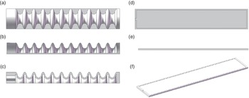
thick restriction layer. Integrating the parameters of the extension layer and the restriction layer, the structure of the FEA obtained is shown in Fig. 2.
Extension layer and restriction layer views (a) The top view of the extension layer; (b) The main view of the extension layer; (c) The section view of the extension layer; (d)The top view of the restriction layer; (e)The main view of the restriction layer; and (f) Restriction layer.

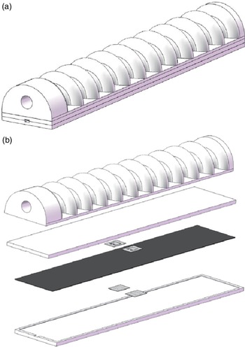
As shown in Fig. 2, the extension layer consists of a distal cap, a proximal cap, and a hydraulic network. The restriction layer contains a empty space for embedding spring steel plates and has a channel for sensor wiring at its top.The assembly diagram of the FEA is shown in Fig. 3.
Fluidic elastomer actuators assembly view (a) Assembly view and (b) Exploded view.

4. Sensing system design
The underwater soft gripper designed in this paper is driven by hydraulic pressure. In order to better control the movement of the soft gripper underwater, we must monitor its real-time water pressure and then control the next movement of the soft gripper according to the water pressure value. Therefore, we need to install water pressure sensors on the soft grippers to monitor their water pressure, but soft grippers are difficult to integrate sensors because of the flexibility of the material and structure. Since the spring steel plate is selected as the restriction layer embedded in the FEA, which provides a platform for sensor integration, a resistance strain gauge with certain flexibility in structure is selected to build a full-bridge circuit to compose the system’s water pressure sensing system. The overall design block diagram of the sensing system is shown in Fig. 4.
Water pressure sensing system.

4.1. Circuit principle
4.1.1. Full bridge circuit
Resistance strain gauges work based on the resistance-strain effect. The resistance-strain effect is a phenomenon that directs the mechanical deformation of a conductor or semiconductor material under the action of an external force, with a corresponding change in its resistance value. Based on this effect, the change in mechanical quantity can be converted into a change in electrical quantity. The resistance-strain effect can be expressed by Eq. (14).
 \begin{equation}{\Delta }{R} = \frac{{\partial }R}{{\partial }l}{\Delta }l + \frac{{\partial }R}{{\partial }l}{\Delta }A + \frac{{\partial }R}{{\partial }l}{\Delta }{\rho } \end{equation}
where
 $R$
is the resistance of the resistance strain gauge,
 $l$
is its length,
 $A$
is its cross-sectional area, and
 $\rho$
is the resistivity of the resistance strain gauge.
The resistance strain gauge sensor is a circuit that uses the resistive strain effect to convert the detected signal into an electrical signal [Reference Hoffmann27]. The strain gauges are applied to the elastomer, and when the elastomer is deformed, the strain gauges are deformed at the same time, causing a change in the resistance of the strain gauges, which is then converted into a voltage change by the measurement circuit. The measurement circuit of the strain gauge sensor usually adopts a bridge circuit. Because of the high sensitivity and low non-linear error of the full bridge circuit, we adopt the full bridge circuit as the measurement circuit of the strain gauge. The operating schematic of the full-bridge circuit is shown in Fig. 5.
Full bridge circuit.

When the FEA is deformed under water pressure, the output signal of the full bridge circuit can be obtained by Eq. (15).
 \begin{equation}{E}_{out}={\frac{{R_2}\times{R_4}}{R_2+R_4}}+\left({\frac{{\Delta }R_1}{R_1}}+{\frac{{\Delta }R_2}{R_2}}+{\frac{{\Delta }R_3}{R_3}}+{\frac{{\Delta }R_4}{R_4}}\right)\times{{E}_{in}} \end{equation}
4.1.2. Signal processing circuit
Since the voltage signal output from the measurement circuit is very weak and easily covered by noise, signal amplification, filtering, and conversion are required before signal acquisition, and the signal processing flow is shown in Fig. 6.
Signal processing process.

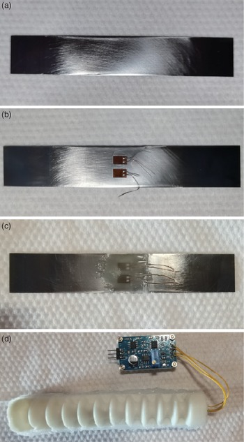
As the core of the analog circuit, the op-amp can be powered by dual or single power supply. Since the total dynamic range, output voltage/current, accuracy, and load immunity of the dual-supply op-amp are better than those of the single-supply op-amp, we use a dual-supply op-amp in the amplifier circuit. The entire signal processing circuit consists of a preamplifier stage, a filter amplifier stage, and a buffer stage. The manufacturing process of the sensing circuit is shown in Fig. 7.
Sensing circuit patching process (a) Spring steel plate patching position processing; (b) Patching: two resistance strain gauges in the middle of each of the upper and lower surfaces of the spring steel plate; (c) Moisture-proofing and insulation: a sticky layer of plastic sheet under the lead wire and a moisture-proofing layer on top of the strain gauges; and (d) Embedding the processed spring steel plates into the restriction layer, the extension layer is glued to the restriction layer and the amplification circuit is connected to the strain gauges.

4.2. Sensor calibration
The signal processed by the amplification circuit is still a voltage signal. In order to achieve the role of measuring the system water pressure, a pressure sensor is installed in the hydraulic circuit in this paper, so as to obtain the standard water pressure value, and the output signal of the resistive strain sensor is compared with the standard water pressure value for fitting, thus calibrating the resistive strain sensor. The no-load water pressure of the pump used in this calibration experiment was 12.8 kPa. Twenty-four sets of data were collected in the experiment, and matlab was used to fit a polynomial to the collected data, and the curve obtained is shown in Fig. 8.
Sensor calibration (a) Fitting the collected data by the least squares method, where * represents the collected data and the green curve is the fitted curve; (b) Comparing the theoretical curve with the fitted curve, where * represents the collected data, the green realization represents the fitted curve, and the black dashed line represents the theoretical curve.

The curve equation obtained by fitting is shown in Eq. (16).
 \begin{equation} P=0.7606{V^3}-3.7409{V^2}+21.7588V-2.7595 \end{equation}
Where
 $P$
is the system water pressure and
 $V$
is the voltage signal output from the resistance strain gauge sensor.
By comparing the theoretical curve and the fitted curve, it can be seen that the two basically overlap. To further evaluate the accuracy of the curve, we calculated the R-square of the curve using matlab. The R-square value of the calculated curve is 0.9933, so the sensor has high accuracy.
4.3. System control process
Two sensors are involved in the system, where sensor 1 is a standard water pressure sensor and sensor 2 is a resistance strain gauge water pressure sensor. Sensor 1 only provides the basis for calibration and testing of Sensor 2 and is not involved in the control of the system. Power supply provides energy for the main controller, pumps, valves, and sensors. The system controls the action of the hydraulic pump and valve through the main controller, thus controlling the action of the soft gripper. When the soft gripper moves, sensor 1 and sensor 2 will sense the system’s real-time water pressure, sensor 2 will pass the water pressure value back to the main controller, and the main controller will use the returned water pressure value to further control the valve and pump action. The system control flow is shown in Fig. 9.
System control process.

5. Experiments
5.1. FEA manufacturing
In this paper, a silicone rubber with a hardness of 30 degrees Shore is used to manufacture the FEA body, and a spring steel plate is used as an insert in the restriction layer of the FEA. A strain gauge is attached to the spring steel plate as described in Chapter 4, and the strain gauge is connected to the amplifier circuit through a lead wire. The mold for the FEA was molded by fused deposition modeling [Reference Şahin28].
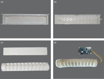
The manufacturing process of the FEA is shown in Fig. 10.
Fluidic elastomer actuator manufacturing process (a) Restriction layer molding: liquid silicone with curing agent added is poured into the restriction layer mold and waited for molding; (b) Extension layer molding: liquid silicone with curing agent is poured into the extension layer mold and waited for molding; (c) Restriction layer and extension layer; and (d) Finished product: the spring steel plate is embedded in the restriction layer and the restriction layer is glued to the extension layer using silicone adhesive.

5.2. Pressure-bearing capacity and bending capacity experiments
In this group of experiments, we tested the ultimate pressure-bearing and bending capacity of the FEA, and also studied the effect of the spring steel plate on the ultimate pressure-bearing and bending capacity of the FEA.
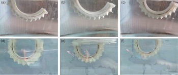
Due to the process, there is a slight difference between the FEAs manufactured each time, this experiment uses different batches of manufactured FEAs to test the pressure-bearing capacity and bending capacity. The experimental results are shown in Fig. 11.
Fluidic elastomer actuator bending capacity and pressure-bearing capacity test (a)
 $-$
(c) Fluidic elastomer actuator with spring steel plate; (d)–(f) Fluidic elastomer actuator without spring steel plate.

By extracting the coordinates of the discrete points of the bending curve of the FEAs in Fig. 11, we plotted the scatter plots of the bending curve of the FEAs, and fitted the discrete points with a circle, the fitting results are shown in Fig. 12.
Fluidic elastomer actuators bending curve.

In this group of experiments, we explored the pressure-bearing and bending capacities of the FEA and the effect of spring steel plates on them. The ultimate pressure and curvature of the FEAs are shown in Table II.
Curvature and ultimate pressure values.

The average pressure of the first three experiments was calculated to be 71.09 kPa with an average curvature of 0.0024, and the average value of the last three experiments was 58.45 kPa with an average curvature of 0.0086. Thus the pressure-bearing capacity of the fluid-elastic actuator was increased by 21.63% after filling with the spring steel plate. The bending capacity was reduced by 72.09% after filling with the spring steel plate.
5.3. Gripper experiment
To verify the grasping performance of the soft gripper and the effect of the spring steel plate on the grasping performance of the soft gripper, we built a four-finger soft gripper system and conducted grasping experiments for different shapes and masses of objects.
5.3.1. Experiment on the effect of the spring steel plate on gripping performance
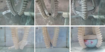
In this experiment, we conducted three sets of grasping experiments on objects of different shapes and masses using soft grippers with and without spring steel plates, to investigate the grasping performance of soft grippers and the effect of spring steel plates on the grasping performance. The experimental results are shown in Fig. 13, where the soft grippers used in experiment (A) to experiment (C) contain spring steel plates, and the soft grippers used in experiment (D) to experiment (F) do not contain spring steel plates.
Gripping experiment (a) A porcelain spoon; (b) A cup with 20 g weights inside; (c) A 200-g porcelain bowl; (d) A porcelain spoon; (e) A cup with 20 g weights inside; and (f) A 184 g porcelain bowl.

The experimental data are shown in Table III.
Comparison experiment data.

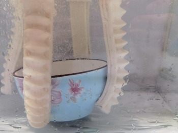
When using the soft gripper with spring steel plates for grasping, all three groups of experiments conducted can achieve stable grasping. However, the use of soft gripper without spring steel plates to grasp the spoon and cup are not stable, there is a gradual decline, and the water pressure of the system at the time of gripping is greater than that of the former. Although it adapted well to the surface profile of the bowl when grasping the porcelain bowl, the soft gripper without spring steel plates was broken due to excessive pressure when trying to pick up the bowl. The experimental result is shown in Fig. 14.
Gripping experiment: The soft gripper without spring steel plates was broken.

5.3.2. Soft gripper sensor accuracy verification
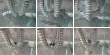
Since the sensor needs to be mounted on a spring steel plate, a soft gripper with a spring steel plate is used in this experiment. In the above experiments, we have used the soft gripper with a spring steel plate for three sets of experiments, and in this experiment we added three sets of experiments on this basis, and the experimental data were collected and recorded. The experimental results are shown in Fig. 15.
Gripper experiment (a) Porcelain spoon; (b) Metal box; (c) Porcelain bowl; (d) A cup with 20 g weight inside; (e) A cup with 30 g weight inside; and (f) A cup with 50 g weight inside.

The experimental data are shown in Table IV.
Gripper experiment data.

The standard value is measured by a standard water pressure sensor, and the experimental value is measured by the resistance strain gauge sensor we built. The average accuracy of the six experiments is 99.64% .
6. Discussion
In this experiment, we verified the pressure-bearing capacity, the bending capacity, the gripping capacity of the FEA, the gripping force enhancement effect of the spring steel plate on the soft gripper, and the accuracy of the sensor.
It can be seen in the experiments of the pressure bearing capacity of the FEA, the spring steel plate increases the pressure bearing capacity of the soft gripper from 58.45 kPa to 71.09 kPa. Its pressure-bearing capacity has been increased by 21.63%. For the bending capability, we extracted the scatter coordinates of the bending profile of the FEAs and fitted these scatter points to the circular arcs to obtain their bending curves as well as their curvatures.The curvature of the FEA with spring steel plate installed decreased by 72.09% compared to the FEA without spring steel plates installed. As can be seen in Fig. 11, the FEAs can still achieve the bending angle required for the application after the bending capacity has been reduced.
In the first group of grasping experiments, we mainly investigated the effect of the spring steel plate on the grasping ability of the soft gripper. From Table III, it can be seen that when the spring steel plate is embedded in the FEA, the soft gripper can get a higher gripping force at a smaller water pressure.
We fitted a polynomial to the data sets A, B, and C, thus calculating the system water pressure to be 48.68 kPa when the gripping force is 1.79 N. We compared the water pressure of each group when the gripping force of the soft gripper was the same and calculated the water pressure reduction. Then,we used the water pressure reduction to measure the effect of the spring steel plate on the enhancement of the soft gripper stiffness and gripping force. The comparison results are shown in Table V.
Enhancement rate analysis.

It can be seen from Fig. 13, the soft gripper can be bent and grasped without the spring steel plate installed. Table 5 shows that the installation of spring steel plates gives the soft grapper greater gripping capacity. The enhancement rate fluctuated within a small range, with an average enhancement rate of 18.34%.
In the second set of grasping experiments, we mainly verified the accuracy of the sensor. The relationship between the weight of the object grasped by the soft gripper and the system water pressure in this experiment is shown in Fig. 16. From the experimental data, we can see that the accuracy of the resistance strain gauge sensor can reach 99.64% .
The relationship between the weight of the target and the system water pressure.

7. Conclusion
In the field of the soft gripper, the lack of grasping force and perception ability are two important problems. In this paper, we design a hydraulic soft gripper for underwater application based on the structure of the FEA, which improves the grasping force and perception ability of soft grippers. We have analyzed this soft gripper and determined the structure of its semicircular hydraulic network and its parameters. To enhance the rigidity of the soft gripper we embedded a spring steel plate in the restriction layer of the soft gripper. And to enhance the sensing capability of the soft gripper, we built a resistance strain gauge based pressure sensor on the spring steel plate, and calibrated the sensor. To operate the soft gripper and verify the soft gripper capability, we built a hydraulic drive system.
In the experiments of pressure-bearing capacity and bending capacity,we tested the ultimate pressure-bearing capacity of the FEA and investigated the effect of the spring steel plate on the pressure-bearing capacity and the bending capacity of the FEA. Experiments have confirmed that the spring steel plate effectively enhances the pressure-bearing capacity of the FEA, and its maximum pressure can reach 71.09 kPa, an increase of 21.6% over that without the spring steel plate installed.Its bending capability is 72.09% lower than that without the spring steel plate, but it still meets the application requirements very well. In the gripping ability experiments, we first investigated the effect of spring steel plates on the gripping ability of the soft gripper. The experiments confirmed that the spring steel plate enhanced the grasping stability and gripping force of the soft gripper. Its average enhancement rate is at 18.34%. Then we conducted the accuracy of the sensor, the experiment confirmed that the sensor has high accuracy.
In contrast to existing solutions that focus on enhancing only one part of the gripping force or sensing capability, this paper combines the two issues and designs a simpler structure and process. The spring steel plate selected in this paper not only effectively improves the stiffness of the soft gripper and thus enhances the gripping force of the soft gripper, but also provides a stable platform for the sensor installation. For sensing, we chose a resistive strain gauge, which is compatible with the flexibility of the soft gripper, as the sensing element of the sensor. It is not only flexible in itself, but its principle of sensing signals based on deformation is also compatible with the working principle of the soft gripper. The accuracy of this sensor also reaches a high standard through the acquisition and processing of the signal.
Acknowledgements
This work was supported by the National Natural Science Foundation of China (No. 51005142), the Innovation Program of Shanghai Municipal Education Commission(No. 14YZ010), and the Natural Science Foundation of Shanghai (No. 14ZR1414900, No. 19ZR1419300) for providing financial support for this work.
Authors’ contributions
Jingke Huang conceived and designed the study, Zhanhua Wang and Jianda Li provided help with the conception of the paper, Zhijie Tang gave guidance on the research and design of this paper.
Financial support
The authors disclosed receipt of the following financial support for the research, authorship, and/or publication of this article
Conflicts of interest
This article has no conflict of interest.
Ethical considerations
This article has no ethical considerations.