1. Introduction
Remarkable strides have been achieved in the field of planetary exploration [Reference Han and Guo1, Reference Norris, Powell, Vona, Backes and Wick2]. While traditional rovers typically employ passive suspension mechanical systems [Reference Estlin, Bornstein, Gaines, Anderson, Thompson, Burl, Castaño and Judd3, Reference Stack, Williams, Calef, Sun, Williford, Farley, Eide, Flannery, Hughes, Jacob, Kah, Meyen, Molina, Nataf, Rice, Russell, Scheller, Seeger, Abbey, Adler, Amundsen, Anderson, Angel, Arana, Atkins, Barrington, Berger, Borden, Boring, Brown, Carrier, Conrad, Dypvik, Fagents, Gallegos, Garczynski, Golder, Gomez, Goreva, Gupta, Hamran, Hicks, Hinterman, Horgan, Hurowitz, Johnson, Lasue, Kronyak, Liu, Madariaga, Mangold, McClean, Miklusicak, Nunes, Rojas, Runyon, Schmitz, Scudder, Shaver, SooHoo, Spaulding, Stanish, Tamppari, Tice, Turenne, Willis and Aileen Yingst4], the Zhurong rover integrated the active and passive suspension systems, enhancing its ability to traverse soft terrains effectively [Reference Zou, Zhu, Bai, Wang, Jia, Shen, Fan, Liu, Wang, Zhang, Yu, Dong, Shu, He, Zhang, Du, Fan, Yang, Zhou, Wang and Peng5]. The emergence of wheeled-legged rovers featuring actively actuated suspension systems introduces a higher degree of flexibility and terrain adaptability due to their increased degrees of freedom and active joints. These systems demonstrate superiority in flexibility and terrain adaptability, which may become a trend in future planetary exploration.
Wilcox et al. [Reference Wilcox, Litwin, Biesiadecki, Matthews, Heverly, Morrison, Townsend, Ahmad, Sirota and Cooper6] argue that wheeled-legged vehicles can get rid of stuck in soft soil compared to purely wheeled vehicles. In addition, they use less energy and roll more efficiently than typical-legged robots. There are some active suspension systems already been developed. MTR [Reference Mahmoud, Huy and Antonios7] has three subsystems, namely the Steering/Drive System, the Shoulder Articulation System, and the Active Compliant Differential Suspension. These subsystems are designed to relocate the CoM and execute operations. ATHLETE rover’s [Reference Hauser, Bretl, Latombe, Harada and Wilcox8] wheels can be locked during walking and used for maneuverability in the form of driving. The planning and control module of the system initially models the terrain and the robot. Subsequently, collisions are detected, and the motion planning employs the Single-Query Bi-Directional (SBL) approach. Finally, the path is smoothed and optimized. LRU [Reference Schuster, Brunner, Bussmann, Büttner, Dömel, Hellerer, Lehner, Lehner, Porges, Reill, Riedel, Vayugundla, Vodermayer, Bodenmüller, Brand, Friedl, Grixa, Hirschmüller, Kaßecker, Márton, Nissler, Ruess, Suppa and Wedler9] is a small and agile rover prototype with four individually powered and steered wheels. The rover receives the velocity command, which is used to calculate the desired velocities and steering angles for each wheel. Slip detection and traction control are implemented to improve performance in rough terrain. This rover features active and passive suspension due to the serial elastic actuators in two bogies. MAMMOTH Rover [Reference Reid, Fitch, Göktoğan and Sukkarieh10] is a wheel-on-leg rover with high degrees of mobility. It employs the HBFMT* planner for continuous domain sampling-based planning, achieving continuous planning in the configuration space of grid-based planners. SherpaTT [Reference Cordes, Kirchner and Babu11] allows itself to change the wheels’ location through a variable footprint. The Ground Adaptation Process (GAP) handles active terrain adaptation by force leveling control. Wheels can be actively lifted and repositioned based on instructions or by detecting sinking wheels. The Body Height Control (BHC) optimizes the rover’s leg workspace by adjusting the body height. The active differential system also can be used passively due to the spring-loaded backlash of the pulley drive. RoboSimian rover [Reference Reid, Meirion-Griffith, Karumanchi, Emanuel, Chamberlain-Simon, Bowkett and Garrett12] utilizes a constrained lookup table to map points within a rectangular workspace to individual joint configurations. A desired end-effector trajectory is generated through two-dimensional interpolation using the planar lookup table.
Rovers with actively actuated suspension systems have demonstrated their capabilities in increasing locomotive maneuverability and escaping from soft soil or steep slopes [Reference Chen, Jin and Chen13, Reference Chen, Yang, Xu, Lu and Hu14]. However, the additional degrees of freedom increase the complexity of the kinematic model and control framework. Zarkandi [Reference Zarkandi15] discusses the problem of dynamic modeling and power optimization for a parallel platform. Han et al. [Reference Han, Guo, Zhao and Li16] propose a unified kinematic modeling method for reconfigurable landing and roving probes with full consideration of six-dimensional foot-terrain interaction. Du et al. [Reference Du, Fnadi and Benamar17] present a model taking into account wheel mobility and rolling-based locomotion for a wheel-legged robot using centroidal dynamics. Wheel velocity and acceleration are derived by both the legged motion and the CoM translation motion reference. Maufroy et al. [Reference Maufroy, Kimura and Takase18] integrate posture and rhythmic motion controls for a general-legged locomotion controller. In addition, a lot of studies have been carried out to investigate the optimal problem in robot trajectory generation and motion planning. Potts et al. [Reference Potts and Da Cruz19] propose an iterative algorithm to minimize energy loss in kinematic chains of legged robots. Tian et al. [Reference Tian and Gao20] present a motion planning method for six-legged robot using optimized the configuration approach. Researchers from ETH [Reference Viragh, Bjelonic, Bellicoso, Jenelten and Hutter21, Reference Bjelonic, Klemm, Lee and Hutter22] use an online trajectory optimization framework based on the ZMP approach for wheeled-legged quadrupedal robots. The hierarchical control framework optimizes whole-body accelerations and contact forces to improve the robustness of the robot. Robosimian [Reference Bellegarda and Byl23] formulates the locomotion problem into a trajectory optimization problem by minimizing the energy costs when moving the end-effector. Zhornyak [Reference Zhornyak and Emami24] analyzes the gait characteristics of a quadruped rover and optimizes these characteristics. Tarokh [Reference Tarokh25] establishes a unified kinematics modeling algorithm with optimization and control for universal robots. Lee et al. [Reference Lee, Bakolas and Sentis26] propose a trajectory generation method that enables the consideration of lots of robotic constraints.
Table 1 presents a comparison of existing active suspension rovers. It can be observed that different structures of rovers demonstrate variations in their planning and control methods. Some of the wheeled-legged platforms only utilize active suspension capabilities [Reference Reid, Fitch, Göktoğan and Sukkarieh10, Reference Cordes, Kirchner and Babu11]. However, some use legs as alternative locomotion. Considering that the control and motion planning algorithms must be developed to fully utilize wheeled-legged rovers’ capabilities [Reference Iagnemma, Kang, Shibly and Dubowsky27], the combination of rolling and crawling could profit a faster and more efficient motion for the platform. Therefore, this paper focuses on proposing an innovative locomotion planning approach. This method effectively leverages the advantages of both wheeled and legged locomotion, preserving the efficiency of wheeled locomotion while retaining the flexibility of legged locomotion. Furthermore, it reduces the lateral sway of the rover during hybrid locomotion.
Comparison of existing active suspension rovers.

Based on our previous works of the terrain-adaptive wheeled-legged (TAWL) rover on its design [Reference He, Sun, Yang, Sun, Xing and Gao28] and mapping method [Reference Zhu, He, Sun, Xing and Gao29], this paper presents a kinematics modeling and hybrid locomotion planning framework for the rover. In the process of building the environment representation map, a plane cluster algorithm is proposed to construct unstructured terrains. This algorithm reduces irregularly shaped obstacles to some flat areas and staircases. When navigating through regularized terrains, the locomotion planning process can be regularized in advance, thereby being simplified. Consequently, the proposed framework in this paper is considered to be a unified solution for wheeled-legged rovers to traverse multiple challenging terrains, while maintaining stability, reducing slippage, and minimizing motors’ energy dissipation. The main contributions of this paper are summarized as follows:
-
1. A locomotion planning framework for wheeled-legged rovers is established. The trajectory generation layer determines the rovers’ gait patterns and parameterizes trajectories, and the motion generation layer generates and optimizes continuous motions to reach the trajectories.
-
2. A hybrid wheeled-legged locomotion strategy is proposed. It regularizes the complex hybrid gait patterns and redundant motion combinations of wheeled-legged rovers and provides a unified solution for hybrid locomotion.
-
3. Calculations, simulations, and prototype experiments are carried out to validate the effectiveness of the proposed algorithms and the rover’s flexibility and maneuverability to traverse irregular terrains
The remainder of this paper is structured as follows. Section 2 introduces the TAWL rover’s structure and establishes its kinematic model. Section 3 presents the locomotion planning framework and the hybrid locomotion strategy. Then, the body trajectories parameterization and regulation, the support polygon and wheels’ trajectories regulation, and the wheel’s camber angle regulation are analyzed. Section 4 optimizes and generates smooth motions based on B-splines. Section 5 verifies the proposed framework and the optimization results through calculations and prototype experiments. Section 6 concludes the paper.
2. System overview
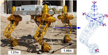
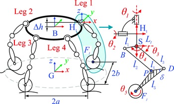
The platform discussed in this paper is the TAWL rover developed for planetary exploration purposes. In such situations, the rover is requested to have high maneuverability, security, energy efficiency, etc. The TAWL rover has 20 degrees of freedom. Legs are designed using planar five-bar mechanisms with two additional revolute joints. Each leg has 3R1T motion characteristics and an active wheel attached to the end-effector, as shown in Fig. 1. The hip coordinate frame {H} is defined as the intersection of four active joint axes. Four legs are arranged symmetrically. The body frame {B} is located at the center of the rover’s body, with the z-axis oriented upwards and the x-axis pointed to the heading direction. The ground coordinate {G} is defined as the projection of the original body frame, with
 $\boldsymbol{z}_{G}$
alone the ground normal, as shown in Fig. 2.
The TWAL rover’s structure.

Structure diagram of the TWAL rover.

2.1. System modeling
The kinematic model is analyzed in this section. Each leg has four inputs except the active wheel, which does not provide additional motion to the leg’s end-effector. The end-effector of the leg is defined at the wheel center, marked as point F. Therefore, input vector
 $\boldsymbol{q}$
is denoted as
 $\boldsymbol{q}_{{F_{j}}}=[\theta _{1},\theta _{2},\theta _{3},\theta _{4}]^{T}, j=1\ldots 4$
.
 $j$
is the index of the legs.
The lower leg is a planar five-bar mechanism defined in frame {S}. The transformation matrix between frame {S} and frame {H} is
 ${S}^{H}{\boldsymbol{T}}{}$
. Mark
 $\boldsymbol{f}$
as the position vector of point F. It can be expressed with respect to hip frame {H} as
 \begin{equation}{}^{H}{\boldsymbol{f}}{}={}^{H}_{S}{\boldsymbol{T}}{}{}^{S}{\boldsymbol{f}}{}\end{equation}
The differential kinematic model of each leg is analyzed as follows. For the parallel mechanism of each leg, the displacement of the end-effector
 $\boldsymbol{x}_{F}$
in the frame {S} is obtained. By differentiating
 $\boldsymbol{x}_{F}$
, the task velocity can be computed from
 \begin{equation}{}^{S}{\boldsymbol{J}_{\chi F}}{}{}^{S}{\dot{\boldsymbol{x}}_{F}}{}={}^{S}{\boldsymbol{J}_{q}}{}\dot{\boldsymbol{q}}\end{equation}
If
 $\boldsymbol{J}_{\chi F}$
has full rank, then the forward kinematic Jacobian matrix can be expressed as
 \begin{equation}{}^{S}{\dot{\boldsymbol{x}}_{F}}{}={}^{\mathrm{S}}{\boldsymbol{J}}{}_{F}\dot{\boldsymbol{q}}={}^{\boldsymbol{S}}{\boldsymbol{J}}{}_{\chi F}^{-1}\;{}^{S}{\boldsymbol{J}_{q}}{}\dot{\boldsymbol{q}}\end{equation}
Take the second derivative, the Hessian matrix is written as
 \begin{equation}{}^{S}{\ddot{\boldsymbol{x}}}{}_{F}={}^{\mathrm{S}}{\boldsymbol{J}}{}_{F}\ddot{\boldsymbol{q}}+\dot{\boldsymbol{q}}^{T}\;{}^{S}{\boldsymbol{H}}{}_{F}\dot{\boldsymbol{q}}\end{equation}
Define the z-axis direction vector as
 $\boldsymbol{s}_{1}$
, x-axis direction vector as
 $\boldsymbol{s}_{2}$
, y-axis direction vector as
 $\boldsymbol{s}_{3}$
. In the hip frame {H}, the velocity of point F satisfies
 \begin{equation}{}^{H}{\dot{\boldsymbol{x}}}{}_{F}=\left[\begin{array}{c} {}^{H}{\boldsymbol{\omega }}{}_{F}\\[5pt] {}^{H}{\boldsymbol{v}}{}_{F} \end{array}\right]=\left[\begin{array}{c@{\quad}c} \mathbf{0}_{3\times 3} & {}^{S}_{H}{\boldsymbol{R}}{}\\[5pt] {}^{S}_{H}{\boldsymbol{R}}{} & \mathbf{0}_{3\times 3} \end{array}\right]{}^{S}{\dot{\boldsymbol{x}}}{}_{F}+\left[\begin{array}{c@{\quad}c} \boldsymbol{s}_{1}\times {}^{H}{\boldsymbol{f}}{} & \boldsymbol{s}_{2}\times {}^{H}{\boldsymbol{f}}{}\\[5pt] \boldsymbol{s}_{1} & \boldsymbol{s}_{2} \end{array}\right]\left[\begin{array}{c} \dot{\theta }_{1}\\[5pt] \dot{\theta }_{2} \end{array}\right]\end{equation}
Together with Eqs. (3) and (5)
 \begin{equation}{}^{H}{\dot{\boldsymbol{x}}}{}_{F}=\left[\begin{array}{c} {}^{H}{\boldsymbol{\omega }}{}_{F}\\[5pt] {}^{H}{\boldsymbol{v}}{}_{F} \end{array}\right]=\left[\begin{array}{c@{\quad}c} \mathbf{0}_{3\times 3} & {}^{S}_{H}{\boldsymbol{R}}{}\\[5pt] {}^{S}_{H}{\boldsymbol{R}}{} & \mathbf{0}_{3\times 3} \end{array}\right]{}^{\mathrm{S}}{\boldsymbol{J}}{}_{F}\left[\begin{array}{c} \dot{\theta }_{3}\\[5pt] \dot{\theta }_{4} \end{array}\right]+\left[\begin{array}{c@{\quad}c} \boldsymbol{s}_{1}\times {}^{H}{\boldsymbol{f}}{} & \boldsymbol{s}_{2}\times {}^{H}{\boldsymbol{f}}{}\\[5pt] \boldsymbol{s}_{1} & \boldsymbol{s}_{2} \end{array}\right]\left[\begin{array}{c} \dot{\theta }_{1}\\[5pt] \dot{\theta }_{2} \end{array}\right]\end{equation}
Each leg’s velocity Jacobian can be expressed in the unified form of a matrix as
 \begin{equation}{}^{H}{\dot{\boldsymbol{x}}}{}_{F}={}^{H}{\boldsymbol{J}_{FK}}{}\dot{\boldsymbol{q}}_{F}\end{equation}
where
 \begin{equation*} \dot{\boldsymbol{q}}_{F}=\left[\dot{\theta }_{1},\dot{\theta }_{2},\dot{\theta }_{3},\dot{\theta }_{4},0,0\right]^{T} \end{equation*}
The whole-body kinematics are analyzed as follows. The transformation matrix from body frame {B} to the ground frame {G} can be expressed as
 \begin{align}\begin{array}{c} {B}^{G}{\boldsymbol{T}}{} \end{array}=\left[\begin{array}{c@{\quad}c} \boldsymbol{R}_{XYZ}\left(\phi,\theta,\psi \right) & {}^{G}{\boldsymbol{b}}{}\\[5pt] \mathbf{0}_{1\times 3} & 1 \end{array}\right]\end{align}
where
 \begin{equation*} \begin{array}{c} {}^{G}{\boldsymbol{b}}{} \end{array}=\left({}^{G}{x_{B}}{},{}^{G}{y_{B}}{},{}^{G}{z_{B}}{}\right)^{T} \end{equation*}
 \begin{equation*} \boldsymbol{R}_{XYZ}\left(\phi,\theta,\psi \right)=\left[\begin{array}{c@{\quad}c@{\quad}c} c\psi c\theta & \textit{c}{\psi }s\theta s\phi -s\psi c\phi & \textit{c}{\psi }s\theta c\phi +s\psi s\phi \\[5pt] s\psi c\theta & \textit{s}{\psi }s\theta s\phi +c\psi c\phi & \textit{s}{\psi }s\theta c\phi -c\psi s\phi \\[5pt] -s\theta & c\theta s\phi & c\theta c\phi \end{array}\right] \end{equation*}
From each hip frame
 $\{H_{j}\}$
to the body frame {B}, the transformation matrix is
 \begin{align} \begin{array}{c} {{}_{H_{j}}}^{\!\!B} {\boldsymbol{T}}{} \end{array}=\left[\begin{array}{c@{\quad}c} \boldsymbol{R}\left({}^{B}{\boldsymbol{z}}{},\dfrac{\left(j-1\right)\pi }{2}\right) & {}^{B}{\boldsymbol{h}_{j}}{}\\[10pt] \mathbf{0}_{1\times 3} & 1 \end{array}\right]\end{align}
where
 ${}^{B}{\boldsymbol{h}_{j}}{}$
is the position vector between frame {B} and frame {H}. The position vector
 $\boldsymbol{f}_{j}$
of the
 $j$
leg can be translated from the frame
 $\{H_{j}\}$
to the frame {B} by
 \begin{equation}{}^{G}{\boldsymbol{f}_{j}}{}={}^{G}_{B}{\boldsymbol{T}}{{}_{H_{\!\!j}}}^{\!\!B}{\boldsymbol{T}}{}{}^{H_{j}}{\boldsymbol{f}_{j}}{}\Longrightarrow {}^{H_{j}}{\boldsymbol{f}_{j}}{}=\left({}^{G}_{B}{\boldsymbol{T}}\;{}^{B}_{\!\!H_{j}}{\boldsymbol{T}}{}\right)^{-1}{}^{G}{\boldsymbol{f}_{j}}{}\end{equation}
Body velocity in the frame {G} is referred to as
 ${}^{G}{\dot{\boldsymbol{x}}_{B}}{}=[\boldsymbol{\omega }_{B}^{T},\boldsymbol{v}_{B}^{T}]^{T}$
, and the end-effector velocity in the frame
 $\{H_{j}\}$
is referred to as
 ${}^{H_{j}}{\dot{\boldsymbol{x}}_{{F_{j}}}}{}=[{}^{H_{j}}{\boldsymbol{\omega }}{}_{F_{j}}^{T},{}^{H_{j}}{\boldsymbol{v}}{}_{F_{j}}^{T}]^{T}.$
Therefore, the end-effector velocity in the frame {G} is
 \begin{equation}\left[\begin{array}{c} {}^{G}{\boldsymbol{\omega }_{{F_{j}}}}{}\\[5pt] {}^{G}{\boldsymbol{v}_{{F_{j}}}}{} \end{array}\right]=\left[\begin{array}{c@{\quad}c} \boldsymbol{I}_{3\times 3} & \mathbf{0}_{3\times 3}\\[5pt] -{}^{G}_{B}{\boldsymbol{R}}{}\left({}^{B\!\!}_{H_{j}}{\boldsymbol{R}}{}{}^{H_{j}}{\boldsymbol{f}_{j}}{}+{}^{B}{\boldsymbol{h}_{j}}{}\right)\times & \boldsymbol{I}_{3\times 3} \end{array}\right]\left[\begin{array}{c} {}^{G}{\boldsymbol{\omega }}{}_{B}\\[5pt] {}^{G}{\boldsymbol{v}}{}_{B} \end{array}\right]+\left[\begin{array}{c@{\quad}c} {}^{G}_{B}{\boldsymbol{R}}\;{}^{B\!\!}_{H_{j}}{\boldsymbol{R}}{} & \mathbf{0}_{3\times 3}\\[5pt] \mathbf{0}_{3\times 3} & {}^{G}_{B}{\boldsymbol{R}}\;{}^{B\!\!}_{H_{j}}{\boldsymbol{R}}{} \end{array}\right]\left[\begin{array}{c} {}^{H_{j}}{\boldsymbol{\omega }_{{F_{j}}}}{}\\[5pt] {}^{H_{j}}{\boldsymbol{v}_{{F_{j}}}}{} \end{array}\right]\end{equation}
Which can be written as
 \begin{equation*} {}^{G}{\dot{\boldsymbol{X}}_{B}}{}={}^{G}_{F_{j}}{\boldsymbol{J}}{}\left[\begin{array}{c} {}^{G}{\boldsymbol{\omega }_{{F_{j}}}}{}\\[5pt] {}^{G}{\boldsymbol{v}_{{F_{j}}}}{} \end{array}\right]-{}^{G}_{F_{j}}{\boldsymbol{J}}{}\left[\begin{array}{c@{\quad}c} {}^{G}_{B}{\boldsymbol{R}}\;{}^{B\!\!}_{H_{j}}{\boldsymbol{R}}{} & \mathbf{0}_{3\times 3}\\[5pt] \mathbf{0}_{3\times 3} & ^{G}_{B}{\boldsymbol{R}}\;{}^{B}_{H_{j}}{\boldsymbol{R}}{} \end{array}\right]\left[\begin{array}{c} {}^{H_{j}}{\boldsymbol{\omega }_{{F_{j}}}}{}\\[5pt] {}^{H_{j}}{\boldsymbol{v}_{{F_{j}}}}{} \end{array}\right] \end{equation*}
It can also be expressed as
 \begin{equation}{}^{G}{\dot{\boldsymbol{x}}_{B}}{}={F_{j}}^{G}{\boldsymbol{J}}{}{}^{G}{\boldsymbol{x}_{{F_{j}}}}{}+{H_{j}}^{B}{\boldsymbol{J}_{{F_{j}}}}{}\dot{\boldsymbol{q}}_{{F_{j}}}\end{equation}
where
 \begin{equation*} \begin{cases} {H_{j}}^{\!\!B}{\boldsymbol{J}_{{F_{j}}}}{}=-\left[\begin{array}{c@{\quad}c} {}^{G}_{B}{\boldsymbol{R}}{}^{B}_{H_{j}}{\boldsymbol{R}}{} & \mathbf{0}_{3\times 3}\\[5pt] \left({}^{G}_{B}{\boldsymbol{R}}\;{}^{B}_{H_{j}}{\boldsymbol{R}}{}{}^{H_{j}}{\boldsymbol{f}_{j}}{}+{}^{G}_{B}{\boldsymbol{R}}{}{}^{B}{\boldsymbol{h}_{j}}{}\right)\times {}^{G}_{B}{\boldsymbol{R}}{}^{B}_{H_{j}}{\boldsymbol{R}}{} & {}^{G}_{B}{\boldsymbol{R}}{}^{B}_{H_{j}}{\boldsymbol{R}}{} \end{array}\right]{}^{H_{j}}{\boldsymbol{J}_{{F_{j}}}}{}\\[5pt] {}^{G}_{F_{j}}{\boldsymbol{J}}{}=\left[\begin{array}{c@{\quad}c} \boldsymbol{I}_{3\times 3} & \mathbf{0}_{3\times 3}\\[5pt] \left({}^{G}_{B}{\boldsymbol{R}}{}^{B}_{H_{j}}{\boldsymbol{R}}{}{}^{H_{j}}{\boldsymbol{f}_{j}}{}+{}^{G}_{B}{\boldsymbol{R}}^{B}{}{}{\boldsymbol{h}_{j}}{}\right)\times & \boldsymbol{I}_{3\times 3} \end{array}\right] \end{cases} \end{equation*}
Listing Eq. (12), for all four legs,
 \begin{equation}{}^{B}{\boldsymbol{J}_{x}}{}{}^{G}{\dot{\boldsymbol{x}}_{B}}{}={}^{B}{\boldsymbol{J}_{q}}{}\dot{\boldsymbol{q}}_{B}+{F}^{G}{\boldsymbol{J}}{}{}^{G}{\dot{\boldsymbol{x}}_{F}}{}\end{equation}
where
 ${}^{B}{\boldsymbol{J}_{x}}{}$
is a 24 × 6 matrix,
 ${}^{B}{\boldsymbol{J}_{q}}{}$
is a 24 × 16 matrix, and
 ${F}^{G}{\boldsymbol{J}}{}$
a 24 × 24 matrix
 \begin{equation*} \begin{cases} {}^{B}{\boldsymbol{J}_{x}}{}=\left[\boldsymbol{I}_{6\times 6},\boldsymbol{I}_{6\times 6},\boldsymbol{I}_{6\times 6},\boldsymbol{I}_{6\times 6}\right]^{T} \\[5pt] {}^{B}{\boldsymbol{J}_{q}}{}=\text{blkdiag}\left({H^{B}_{1}}{\boldsymbol{J}_{F}}{},{H^{B}_{2}}{\boldsymbol{J}_{F}}{},{H^{B}_{3}}{\boldsymbol{J}_{F}}{},{H^{B}_{4}}{\boldsymbol{J}_{F}}{}\right) \\[5pt] {F}^{G}{\boldsymbol{J}}{}=\text{blkdiag}\left({F^{G}_{1}}{\boldsymbol{J}}{},{F^{G}_{2}}{\boldsymbol{J}}{},{F^{G}_{3}}{\boldsymbol{J}}{},{F^{G}_{4}}{\boldsymbol{J}}{}\right) \\[5pt] \dot{\boldsymbol{q}}_{B}=\left[\begin{array}{c} \dot{\boldsymbol{q}}_{F^{T}_{1}}\left(1\colon 4\right),\dot{\boldsymbol{q}}_{F_{2}}^{T}\left(1\colon 4\right),\dot{\boldsymbol{q}}_{F_{3}}^{T}\left(1\colon 4\right),\dot{\boldsymbol{q}}_{F_{4}}^{T}\left(1\colon 4\right) \end{array}\right]^{T}\\[5pt] {}^{B}{\dot{\boldsymbol{x}}_{F}}{}=\left[\begin{array}{c} \dot{\boldsymbol{x}}_{F_{1}}^{T},\dot{\boldsymbol{x}}_{F_{2}}^{T},\dot{\boldsymbol{x}}_{F_{3}}^{T},\dot{\boldsymbol{x}}_{F_{4}}^{T} \end{array}\right]^{T} \end{cases} \end{equation*}
Hence, the inverse and forward velocity equations of the rover can be expressed as
 \begin{align} \begin{cases} \dot{\boldsymbol{q}}_{B}={}^{B}{\boldsymbol{J}_{q}^{+1}}{}{}^{B}{\boldsymbol{J}_{x}}{}{}^{G}{\dot{\boldsymbol{X}}_{B}}{}-{}^{B}{\boldsymbol{J}_{q}^{+1}}{}{F}^{G}{\boldsymbol{J}}{}{}^{G}{\dot{\boldsymbol{X}}_{F}}{}\\[5pt] {}^{G}{\dot{\boldsymbol{x}}_{B}}{}={}^{B}{\boldsymbol{J}_{x}^{+1}}{}{}^{B}{\boldsymbol{J}_{q}}{}\dot{\boldsymbol{q}}_{B}+{}^{B}{\boldsymbol{J}_{x}^{+1}}{}{F}^{G}{\boldsymbol{J}}{}{}^{G}{\dot{\boldsymbol{X}}_{F}}{} \end{cases}\end{align}
When the ground is hard enough and frictional,
 ${}^{G}{\dot{\boldsymbol{x}}_{{F_{j}}}}{}=\mathbf{0}_{6\times 1}$
.
2.2. Wheel-ground contact modeling
Due to the end-effector having 3 rotation degrees and 1 translation degree, contact interactions between the wheel and ground could be complex. In Section 2.1, the position of the end-effector
 $\boldsymbol{f}$
and its kinematics are discussed. However, when a cylindrical wheel is mounted on the end-effector, the orientation of the wheel center frame affects the camber angle. Thus, the synthesis velocity needs to be considered.
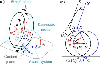
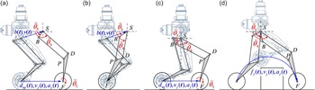
For the simplification of the calculation, the ground and the wheel are assumed to be hard enough without taking into account deformations. As illustrated in Fig. 3(a), R and w are the radius and width of the wheel. Point F is attached to the end-effector of the leg and located at the center of the wheel. It is regarded as frame {F} and does not rotate with the actuation of the wheel. The x-axis is defined perpendicular to the ground normal, and the y-axis coincides with the wheel axis.
 $\lambda$
is the angle between vectors
 $\boldsymbol{z}_{F}$
and
 $\boldsymbol{s}_{1}$
. It can be calculated from the kinematic model. Point C is the contact point, regarded as frame {C}, with the z-axis parallel to the contact normal and the y-axis perpendicular to the ground normal. Notably, the contact surface may not be the ground. Therefore, contact normal does not necessarily coincide with
 $\boldsymbol{s}_{1}$
. ϕ is the camber angle. It is defined as the angle between the vector
 $\boldsymbol{z}_{C}$
and the wheel plane. It cannot be obtained directly.
 $\rho$
is the angle between vector
 $\boldsymbol{z}_{C}$
and
 $\boldsymbol{s}_{1}$
. Point C is located at the midpoint of the contact line when the camber angle remains zero. Therefore,
 $\| {}^{F}{\boldsymbol{C}}{}\| =\begin{cases} \sqrt{R^{2}+w^{2}/4}\varphi \neq 0\\[5pt] R \varphi =0 \end{cases}$
. Assume that the vision system already obtains the convex envelope of the obstacle. Hence, the contact normal
 $\boldsymbol{z}_{C}$
is known in advance. The transformation matrix between the frame {F} and the frame {C} can be expressed as
Wheel-ground contact model.

 \begin{align}\begin{array}{c} {}^{F}_{\mathrm{C}}{\boldsymbol{T}}{} \end{array}=\left[\begin{array}{c@{\quad}c} {}^{F}_{C}{\boldsymbol{R}}{} & {}^{F}{\boldsymbol{C}}{}\\[5pt] \mathbf{0}_{1\times 3} & 1 \end{array}\right]=\begin{cases} \mathrm{Rot}\left(y,\rho \right)\mathrm{Rot}\left(x,-\lambda \right)\text{Trans}\left(x,-R\right)\text{Trans}\left(y,-w/2\right) \quad \varphi \neq 0\\[5pt] \mathrm{Rot}\left(y,\rho \right)\text{Trans}\left(x,-R\right) \quad\varphi =0 \end{cases}\end{align}
With the rotation velocity
 $\boldsymbol{\omega }_{w}$
, the synthesis velocity of the contact point on the wheel
 $C'$
satisfies
 \begin{align} \begin{cases} {}^{G}{\boldsymbol{\omega }_{C'}}{}={}^{G}{\boldsymbol{\omega }_{F}}{}+\boldsymbol{\omega }_{w} \\[5pt] {}^{G}{\boldsymbol{v}_{C'}}{}={}^{G}{\boldsymbol{v}_{F}}{}+{F}^{G}{\boldsymbol{T}}{}\left(\boldsymbol{\omega }_{w}\times {}^{F}{\boldsymbol{C}}{}\right) \end{cases}\end{align}
When the wheel is not actuated, it cannot rotate relative to the end-effector. Due to the wheel’s radius and the arc surface, the contact point changes with the angle of the shank to the ground. A small angular change leads to a certain rolling distance and causes interference and slippage between wheels. This offset will not affect the wheel position during foot tip trajectory planning. But during the base trajectory planning, changes in contact points should be considered when the support points of the rover are supposed to remain constant. Assuming that the lateral contact line is collinear to the wheel axis. In Fig. 3(b),
 $S_{0}D_{0}F_{0}C_{0}$
is the leg’s initial position. SDFC is the desired position.
 $\textit{S' D' F' C' }$
is the actual position without control compensation. When the angle between the shank and the ground changes for
 $\Delta \boldsymbol{\unicode{x1D6F7}}$
, it causes the wheel to roll by
 $\Delta \boldsymbol{\unicode{x1D6F7}}$
, and the wheel center moves for
 $\Delta \boldsymbol{d}$
. Given the desired position
 $\boldsymbol{f}_{j}$
, and the initial posture of the rover
 $\boldsymbol{f}_{j0}$
, from kinematic Eq. (10), the desired angle between shank and ground
 $\boldsymbol{\unicode{x1D6F7}}_{j}$
and its initial position
 $\boldsymbol{\unicode{x1D6F7}}_{j0},j=1\ldots 4$
are obtained. Therefore,
 \begin{equation}\Delta \boldsymbol{d}_{j}=\left(\boldsymbol{\unicode{x1D6F7}}_{j}-\boldsymbol{\unicode{x1D6F7}}_{j0}\right)\cdot R\end{equation}
The command position in the control process follows
 \begin{equation}\boldsymbol{f}_{j\mathrm{cmd}}=\boldsymbol{f}_{j}-\boldsymbol{f}_{j0}-\Delta \boldsymbol{d}_{j}\end{equation}
3. Hybrid locomotion planning
3.1. Locomotion planning framework
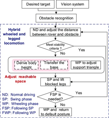
Generally, the rover can achieve three types of locomotion: legged locomotion, including static walking, trotting, etc.; wheeled locomotion; and hybrid locomotion. Since legged and wheeled locomotions have been studied thoroughly, they will not be repeated anymore. The proposed hybrid locomotion adds an extra wheeling phase into the stance and swing phases based on the feasible gait patterns and utilizes the wheeled motion to adjust the support polygon, maintain static stability, and result in non-lateral movement. For more clarity, the swing phase (SP) is defined as at least one leg swinging. The wheeling phase (WP) is defined as at least one wheel-rolling. Hereinafter, four wheels rolling at the same time at the same speed is called normal driving (ND). The stance phase is defined as all the legs in the support condition, and no wheel is rolling.
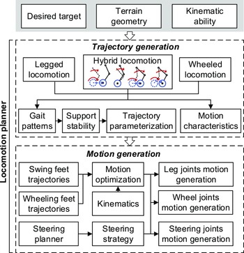
The characteristic of this locomotion planning framework is that it provides an intuitive and unified approach for wheeled-legged rovers to traverse obstacles, achieving the purpose of simplifying the decision-making process and responding quickly when facing irregular terrains. By establishing the mapping relationship between terrain geometry and locomotion methods, the rover does not have to recalculate similar motions in similar situations every time, but instead identifies the obstacle classes and efficiently determines the locomotion method. Its framework is separated into two levels, as shown in Fig. 4. The trajectory generation layer determines gait patterns and yields corresponding trajectories according to desired targets, terrain geometry, and kinematics ability. Furthermore, wheeled motions are generated to ensure stability while taking into account the maximum use of the working space of the legs. The motion generation layer optimizes the planned trajectories and generates continuous joint motions to reach the trajectory. Feet trajectories are generated by utilizing B-splines. Besides, constraints are imposed to ensure safety and stability. The chamber angle is required to remain zero when the wheels are in contact with the ground or obstacle.
Locomotion planning framework.

3.2. Hybrid locomotion strategy
Instead of inducing lateral movement of the CoM when raising legs, the proposed hybrid locomotion strategy utilizes the wheeling phase to adjust the supporting triangle and cause non-lateral movement. Its framework illustration is shown in Fig. 5. Given the desired target and the obstacle geometry obtained by the vision system, the locomotion planning system recognizes the obstacle and generates the following motions. The rover approaches the obstacle by normal driving. When the obstacle is positioned at the extreme limits of the leg’s reachable space, the rover raises the hip and adjusts its position for optimal obstacle negotiation, enhancing its performance in crossing obstacles. Consequently, the rover elevates its body to an appropriate height to prevent collisions and expand the workspace. Legs adopt the wheeling phase to adjust the support triangle simultaneously. Subject to the stability criteria being met, the swing phase is adopted to cross the obstacle and repeats the previous steps to prepare for the following steps. At least two swing phases are needed, as the first lifts the front leg and the second lifts the hind leg.
3.3. Base trajectory parameterization and regulation
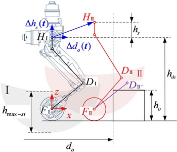
The rover’s base only moves in the heading direction or shifts vertically. In the normal driving stage, the rover detects the obstacle at the distance
 $d_{o}$
and approaches it with
 $\Delta d_{o}(\boldsymbol{t})$
. The base is being transferred upward for
 $h_{s}$
to maximize the reachable space and avoid collision between the shank and the obstacle. In Fig. 6, the gray shaded area is the reachable space of the end-effector during default normal driving, and the red shaded area corresponds to the reachable space after shifting the base. At this point, the hip frame moves to
 $\{H_{\mathrm{II}}\}$
, where the maximum lift height
 $h_{\text{max-st}}$
covers the step edge. Purple shank
 $F_{\mathrm{II}}D_{\mathrm{II'}}$
shows the collision condition without base shift.
 $\boldsymbol{f}$
is the trajectory of end-effector F. During approaching, the base trajectory is expressed as
 \begin{align} \begin{cases} {}^{\text{ND}}{b_{x}}{}\left(\boldsymbol{t}\right)={}^{\text{ND}}{b_{x0}}{}+\Delta d_{o}(\boldsymbol{t})\\[5pt] {}^{\text{ND}}{b_{z}}{}\left(\boldsymbol{t}\right)={}^{\text{ND}}{b_{z0}}{}+\Delta h_{s}(\boldsymbol{t}) \end{cases}\end{align}
Hybrid locomotion strategy.

Illustration of the collision model and the base trajectory in the approaching stage.

The final position of F in the coordinate system {H} can be expressed as
 \begin{equation}{}^{H}{\boldsymbol{f}}{}=[0,0,{h_{\text{de}}}+{h_{s}}]^{T}\end{equation}
where
 $h_{\text{de}}$
is the default height of the rover. Combined with Eq. (1),
 \begin{equation}{}^{S}{\boldsymbol{f}}{}={S}^{H}{\boldsymbol{T}^{-1}}{}{}^{H}{\boldsymbol{f}}{}\end{equation}
Bringing Eq. (21) into the inverse kinematic equation,
 $\theta _{3}$
and
 $\theta _{4}$
can be derived. With the forward kinematic of point
 $D$
, its position in the frame {F} can be expressed as
 $[{}^{F}{x}{}_{D},{}^{F}{y}{}_{D},{}^{F}{z}{}_{D}]^{T}=[l_{3}c_{3},0,h_{de}+h_{s}-L_{1}-R-l_{3}s_{3}]^{T}$
, where
 $L_{1}$
is the offset along the z-axis between the origin of the frame {H} and frame {S}. Therefore, in order to avoid collisions, the base trajectory should satisfy
 \begin{equation}h_{o}-R\leq \frac{{}^{F}{z}{}_{D}}{{}^{F}{x}{}_{D}}d_{b}\Rightarrow \Delta h_{s}\left(\boldsymbol{t}\right)\geq \frac{l_{3}c_{3}\left(h_{o}-R\right)}{d_{o}-\Delta d_{o}\left(\boldsymbol{t}\right)}+L_{1}+R+l_{3}s_{3}-h_{\text{de}}\end{equation}
3.4. Wheel trajectory parameterization and regulation
A mechanical system is statically balanced if the projection of CoM to the ground lies within the polygon formed by supporting legs. Support polygon needs to be planned in the wheeling phase to ensure the rover’s stability and in preparation for the following swing phase. The following swing leg and the base movement both need to be taken into account. Positions of four wheel-ground contact points are known, expressed in the projection frame of the new CoM as
 $\boldsymbol{p}_{j},j=1,\ldots,4$
.
 $\boldsymbol{p}'_{\!\!j}$
is the position after the wheeled motion. Therefore,
 \begin{equation}\boldsymbol{p}'_{\!\!j}=\boldsymbol{p}_{j}+\boldsymbol{d}_{wj},j=1,\ldots,4\end{equation}
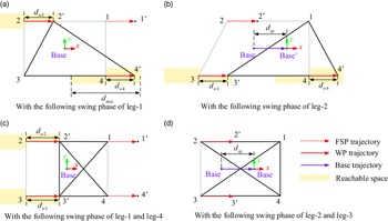
The position relationship between obstacles and the rover can be roughly divided into two types: obstacle on one side, and obstacle on both sides. Figure 7 shows the leg arrangements of two typical hybrid locomotion strategies. Based on them, variant hybrid locomotion with the same gait sequence logic but more step circles can be generated.
Illustration of two typical hybrid locomotion strategies.

When one of the front legs is blocked, wheels on the diagonal of the rover roll forward to prepare for the swing. When one of the hind legs is blocked, the rover rolls wheels on the opposite side. Mark the support leg as
 $a,b,c$
, leg a is on one side, leg b and c are on the other, and b is in front of c. Position vectors of four legs in Fig. 7(a) satisfy
 \begin{align} \begin{cases} \dfrac{\left| \boldsymbol{p}_{a}\times \boldsymbol{p}_{b}\right| }{2\left| \boldsymbol{p}_{a}-\boldsymbol{p}_{b}\right| }\geq S_{\min },\dfrac{\left| \boldsymbol{p}_{a}\times \boldsymbol{p}_{\boldsymbol{c}}\right| }{2\left| \boldsymbol{p}_{a}-\boldsymbol{p}_{c}\right| }\geq S_{\min } \\[12pt] \left(\boldsymbol{p}_{a}+\boldsymbol{p}_{b}\right)_{x}\gt 0,\left(\boldsymbol{p}_{a}+\boldsymbol{p}_{c}\right)_{x}\lt 0\\[5pt] 0\leq \left\| \boldsymbol{d}_{wi}\right\|,\left\| \boldsymbol{d}_{w\mathrm{j}}\right\| \leq \left\| \boldsymbol{d}_{sp}\right\| /2 \end{cases}\end{align}
where
 $(\boldsymbol{p}_{a}+\boldsymbol{p}_{b})_{x}$
is the component of the vector
 $(\boldsymbol{p}_{a}+\boldsymbol{p}_{b})$
on the x-axis.
 $d_{wi},d_{wj}$
are the rolling distance. The second formula indicates the CoM is within the support triangle.
 $d_{\max }$
is the maximum reachable distance.
 $S_{\min }$
is the minimum longitudinal stability margin.
 $S_{\min }=(d_{F}+d_{R})/8$
, where d
F
and d
R
are the distances from the CoM to the front and rear boundaries of the supporting polygon, respectively.
If the front legs are both blocked, the hind wheels roll forward for
 $\boldsymbol{d}_{wi}$
,
 $\boldsymbol{d}_{wj}$
.
 $\boldsymbol{d}_{\boldsymbol{wi}}$
equals to
 $\boldsymbol{d}_{wj}$
and satisfies
 \begin{align}\begin{cases} \boldsymbol{d}_{wi}\sin \tan ^{-1} \dfrac{2b}{2a-d_{wi}}\geq 2S_{\min } \\[10pt] \boldsymbol{d}_{wi}\leq a-S_{\min } \\[5pt] 0\leq \left\| \boldsymbol{d}_{wi}\right\| =\left\| \boldsymbol{d}_{wj}\right\| \leq \left\| \boldsymbol{d}_{sp}\right\| /2 \end{cases}\end{align}
where
 $\boldsymbol{d}_{wp}$
is the base shifting trajectory, determined by Eq. (22). The first and second formulas in Eq. (25) constrain the CoM within the double support triangle. A cycle of gait locomotion is completed with the rolling of leg 2 and leg 3, and the legged movement of leg 1 and leg 4. Through the above analysis, the rolling distance in the wheeling phase is calculated.
3.5. Wheel camber angle regulation
When the wheel hits the ground or an obstacle, the camber should be kept at zero to ensure full contact. Therefore, an orientation constraint is applied. According to Section 2.1, the transformation matrix between the frame {F} and the ground can be expressed as
 \begin{equation}{}^{G}_{F}{\boldsymbol{T}}{}={}^{G}_{B}{\boldsymbol{T}}{}^{B}_{H}{\boldsymbol{T}}{}^{H}_{F}{\boldsymbol{T}}{}=\left[\begin{array}{c@{\quad}c} \boldsymbol{R}_{XYZ}\left(\phi,\theta,\psi \right) & {}^{G}{\boldsymbol{f}}{}\\[5pt] \mathbf{0}_{3\times 1} & 1 \end{array}\right]\end{equation}
The contact point position vector in the ground frame
 ${}^{G}_{C}{\boldsymbol{T}}{}$
can be obtained from the map of the vision system. Let
 $\varphi =0$
, Eq. (15) can be simplified as
 \begin{equation}{}^{F}_{\mathrm{C}}{\boldsymbol{T}}{}=\mathrm{Rot}\left(y,\rho \right)\text{Trans}\left(x,-R\right)\end{equation}
Combine Eqs. (26) and (27), the full contact regulation is written as
 \begin{equation}{}^{G}_{F}{\boldsymbol{T}}{}={}^{G}_{C}{\boldsymbol{T}}{}^{F}_{C}{\boldsymbol{T}^{-1}}{}\end{equation}
Therefore, the posture of wheels during the wheeling phase and the initial and final posture during the swing phase are restricted.
4. Motion generation and optimization
4.1. Smooth trajectory generation
B-splines are utilized to generate continuous trajectories for the legs. There are 4 cases of hybrid locomotion for each leg, as shown in Fig. 8. (a) corresponds to the wheeling phase with base adjustment. (b) is the leg support phase with base adjustment. (c) is the wheeling phase without base adjustment. (d) is the swinging phase of the leg.
Cases of hybrid locomotion for each leg.

The key points on the desired trajectory in Cartesian space with respect to the {S} frame are given, marked as
 $\boldsymbol{f}_{s}$
, with the initial point
 $\boldsymbol{f}_{0}$
and the final point
 $\boldsymbol{f}_{n-k+1},0\leq s\leq n-k+1$
. The normalized formula is expressed as
 \begin{equation}f\left(\tau \right)=\sum _{i=0}^{n}p_{i}N_{i,k}(\tau )\end{equation}
where
 $f(\tau )$
is the position of the point on the trajectory at node
 $\tau$
,
 $p_{i}$
is the control point,
 $N_{i,k}(\tau )$
is the spline basis function with
 $k$
being its degree.
 $n+1$
is the number of the control points.
 $\boldsymbol{\tau }=[\tau _{0},\ldots,\tau _{m}]$
is the node vector,
 $m=n+k+1,\tau _{i}\in [0,1]$
.
 $N_{i,k}(\tau )$
satisfies
 \begin{align} \begin{cases} N_{i,0}\left(\tau \right)=\begin{cases} 1, \tau _{i}\leq \tau \leq \tau _{i+1}\\[5pt] 0,\text{ otherwise } \end{cases} \\[15pt] N_{i,k}(\tau )=\dfrac{\tau -\tau _{i}}{\tau _{i+k}-\tau _{i}}N_{i,k-1}\left(\tau \right)+\dfrac{\tau _{i+k+1}-\tau }{\tau _{i+k+1}-\tau _{i+1}}N_{i+1,k-1}\left(\tau \right) \end{cases}\end{align}
The normalized node vector
 $\boldsymbol{\tau }$
can be expressed as
 \begin{align}\begin{cases} \tau _{0}=\tau _{1}=\ldots =\tau _{k}=0\\[5pt] \tau _{j}=\tau _{j-1}+\left| \Delta t_{j}\right| /T,j=k+1,k+2,\ldots,n\\[5pt] \tau _{n+1}=\tau _{n+2}=\ldots =\tau _{n+k+1}=1 \end{cases}\end{align}
where
 $T$
is the total time consumption. Time intervals between different nodes
 $\Delta t_{j}$
can be obtained by optimization equation.
According to the De Boor formula, the rth derivative of
 $f(\tau )$
can be expressed as
 \begin{equation}f^{r}\left(\tau \right)=\sum _{i}^{n-r}p_{i}^{r}N_{i,k-r}(\tau )\end{equation}
where
 $p_{i}^{r}$
is the rth derivative of the control point, expressed as
 \begin{equation}p_{i}^{r}=\begin{cases} p_{i}\quad r=0\\[5pt] \dfrac{k-r+1}{\tau _{i+k+1}-\tau _{i+r}}(p_{i+1}^{r-1}-p_{i}^{r-1})\quad 0\lt r\leq k \end{cases}\end{equation}
Therefore, with discrete points vector
 $\boldsymbol{f}$
on the planned trajectory, the control points could be derived by solving Eq. (29) under the boundary derivative conditions of the trajectory.
 \begin{align}\begin{cases} \left.f^{r}\right| _{\tau =0}=f_{0}^{r}\\[5pt] \left.f^{r}\right| _{\tau =1}=f_{1}^{r} \end{cases} r=1,2,3\end{align}
4.2. Motion optimization
With the planned trajectory of the end-effector, the motion generation algorithm should generate smooth and continuous trajectories to meet the requirements while optimizing some performance indexes. Assumed that joint angle rotates from the position
 $\boldsymbol{\theta }_{m}$
to
 $\boldsymbol{\theta }_{n}$
during time
 $T$
. In order to minimize the energy dissipation in the motor, the solution to the following equation needs to be determined.
 \begin{equation}\boldsymbol{I}\dot{\boldsymbol{\omega }}=\boldsymbol{M}\end{equation}
s.t.
 \begin{equation}\int _{0}^{T}\boldsymbol{\omega }\left(t\right)dt=\boldsymbol{\theta }_{n}-\boldsymbol{\theta }_{m}\end{equation}
where
 $\boldsymbol{I}$
is the moment of inertia of a rigid body, and it is constant.
 $\boldsymbol{\omega }=\dot{\boldsymbol{\theta }}$
.
 $\boldsymbol{M}$
is the joint torque. The performance index to be minimized is set to be:
 \begin{equation}\int _{0}^{T}\boldsymbol{M}^{T}\boldsymbol{QM}dt\end{equation}
where
 $\boldsymbol{Q}$
is an identity matrix. In summary, for a total number of I drive joints, the cost function is formulated as
 \begin{align}& \min\qquad\qquad\qquad\qquad \xi =\sum _{i=1}^{I}\sqrt{\frac{1}{T}\left(\sum _{j=k+1}^{n-k}\left[\left.\ddot{\boldsymbol{\theta }}_{i}\right| _{t={t_{j}}}\right]^{2}\Delta t_{j}\right)}\\[5pt]& \;\;s.t.\qquad\qquad\qquad\qquad \nonumber\\[4pt] &\qquad\qquad\qquad\qquad \begin{cases} \begin{cases} \dot{\boldsymbol{\theta }}=\boldsymbol{J}_{F}^{-1}\dot{\boldsymbol{X}}_{F} \\[5pt] \ddot{\boldsymbol{\theta }}_{i}=\left[\boldsymbol{J}_{F}^{-1}\left(\ddot{\boldsymbol{X}}_{F}-\dot{\boldsymbol{\theta }}^{T}\boldsymbol{H}_{F}\dot{\boldsymbol{\theta }}\right)\right]_{i\colon } \end{cases} \\[5pt] \sum _{j=k+1}^{n-1}\Delta t_{j}=T\\[5pt] \left\| \boldsymbol{d}_{w-\min }\right\| \leq \left\| \boldsymbol{d}_{w}\right\| \leq \left\| \boldsymbol{d}_{w-\max }\right\| \\[5pt] \boldsymbol{b}=\boldsymbol{b}_{0}+\boldsymbol{d}\\[5pt] {}^{G}{\boldsymbol{f}}{}-\boldsymbol{f}_{\text{convex}}\gt 0\\[5pt] {}^{G}_{F}{\boldsymbol{T}}{}={}^{G}_{C}{\boldsymbol{T}}{}^{F}_{C}{\boldsymbol{T}^{-1}}{}\\[5pt] \left\| \dot{\boldsymbol{\theta }}_{i}\right\| \leq \dot{\theta }_{\max },\left\| \ddot{\boldsymbol{\theta }}_{i}\right\| \leq \ddot{\theta }_{\max } \end{cases} \nonumber\end{align}
where
 $\dot{\theta }_{\max },\ddot{\theta }_{\max }$
corresponding to the maximum velocity and acceleration of joint i.
 $\boldsymbol{f}_{\text{convex}}$
refers to the convex shape of the obstacle. It is derived from the vision system.
5. Simulations and experiments
5.1. Simulations of trajectory generation
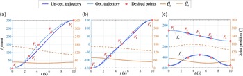
For cases (a), (b), and (c) in Fig. 8, the end-effector F moves in a straight line with respect to the reference frame {S}. Take case (a) as an example. Take
 $k=3$
as 3-degree B-splines are utilized throughout the optimization. The node vector is expressed as
 \begin{equation}\boldsymbol{\tau }=\left[\underset{4}{\underbrace{0,..,0,}}\tau _{4},\tau _{5},\ldots,\tau _{n-1},\tau _{n},\underset{4}{\underbrace{1,\ldots,1}}\right]\end{equation}
Define
 \begin{equation}\tau _{5}-\tau _{4}=\Delta t_{1},\tau _{6}-\tau _{5}=\Delta t_{2},\ldots,\tau _{n}-\tau _{n-1}=\Delta t_{n-4}\end{equation}
The optimization function inputs are desired points on the planned trajectories. Select 5 points, corresponding to the node vector
 $\tau _{3},\tau _{4},\ldots,\tau _{7}$
, with the initial point at
 $\tau _{3}$
and the final point at
 $\tau _{7}$
. Variables
 $\Delta t_{1},\Delta t_{2},\ldots,\Delta t_{4}$
are needed to solve from the optimization equation. Use the interior point solver to solve the problem. Optimization and fitted results are shown in Fig. 9(a). Qualitatively speaking, the optimization process is to smooth the speed curve of the driving joints, reduce the fluctuation, and keep the motions as uniform as possible, thereby reducing the motors’ energy dissipation.
Optimized and fitted trajectories. (a) represents the optimization result for case (a). (b) represents the optimization result for case (c). (c) represents the optimization result for case (d).

The unoptimized trajectory is obtained by moving
 $\;\boldsymbol{f}_{x}$
with a constant velocity along the x-axis while keeping the velocity at 0 at both ends. The position, velocity, and acceleration of
 $\;\boldsymbol{f}$
can be derived by the forward kinematic model as Eqs. (1), (2) and (4).
 ${}^{F}{\boldsymbol{c}}{}$
can be calculated by Eqs. (15) and (28). Accordingly, the driving velocity of the wheel
 $\boldsymbol{\omega }_{w}$
is expressed as Eq. (16). Therefore, leg motions of case (a) are generated.
The optimization process of case (b) is similar to (a), except the wheel is not actuated. However, for case (c), assume that the node vector
 $\tau _{j},j=k+1,k+2,\ldots,n$
is distributed symmetrically about the origin of the hip coordinate system and
 $(n-k)$
is odd. Define
 \begin{equation}\tau _{5}-\tau _{4}=\Delta t_{1},\tau _{6}-\tau _{5}=\Delta t_{2},\ldots,\tau _{\frac{n+k+1}{2}}-\tau _{\frac{n+k-1}{2}}=\Delta t_{f},\tau _{\frac{n+k+3}{2}}-\tau _{\frac{n+k+1}{2}}=\Delta t_{f},\ldots,\tau _{n}-\tau _{n-1}=\Delta t_{1}\end{equation}
Thereby,
 $\left(\frac{n-k-1}{2}\right)$
variables need to be solved from the optimization equation. Select 5 points on the desired trajectory corresponding to the node vector
 $\tau _{3},\tau _{4},\ldots,\tau _{7}$
. Variables
 $\Delta t_{1},\Delta t_{2}$
are needed to calculate from the optimization problem. Results are shown in Fig. 9(b). All curves go through the midpoint. Wheel velocity is also obtained by Eq. (16). It is worth noting that under the constraints of the joint velocity and acceleration, the ratio of time intervals obtained from the optimization results affects the shape of the fitted curve. However, time scale elongates the curve. Therefore, time is normalized to facilitate the comparison of optimization results.
Performance comparison of different trajectory types.

Unit:
 $^{\circ}/s^{2}$
.
In case (d), the trajectory of the end-effector is also symmetrical about the origin of the hip coordinate system, as shown in Fig. 9(c). The upper two curves are the x-axis components of the end-effector trajectory, and the lower two curves correspond to the z-axis components. Equation (41) is utilized to define the node vector. Desired points are distributed at the initial, final, and highest points of the curve.
To evaluate the proposed algorithm, same inputs are applied to different types of trajectory generation methods with the same tolerance settings. Performance comparison results are shown in Table 2. Opt. B-spline refers to the method utilized in this paper, which is based on B-spline curve optimization. Un-opt. B-spline refers to the B-spline curve fitting method. It approximates data points using a smooth curve represented by B-spline functions, which are characterized by being piecewise-defined polynomial functions. Polyfitting approximates data points using a polynomial function and minimizes the disparity between actual data and predicted values through algorithms like least squares regression. LSPB is short for the Linear Segment with Parabolic Blend fitting method. It divides curves into multiple linear segments, each representing a portion of the data. The transition between adjacent linear segments is achieved by smoothly blending them using parabolic curves. Both cost function values and acceleration amplitude are evaluated, indicating the energy efficiency and curve performance, respectively. Worth noting that the acceleration amplitude in this table refers to the difference between the maximum and minimum acceleration in the joint space. In case (a–c), Poly and LSPB fit the straight line trajectories through endpoints, while B-spline fits the trajectory through points sequence on the path, so the optimization effect is not very prominent. However, when the end trajectory is complex, for example, in case (d), interpolation through poly will bring poor trajectory performance and high costs.
Energy costs of different locomotion strategies for the simulations.

Comparison of existing methods.

5.2. Simulation of hybrid locomotion
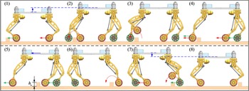
The proposed hybrid locomotion strategy is tested in two simulation scenarios using the TAWL rover. They are two basic gait strategies for crossing obstacles. Simulation I is to step over the obstacle on the left side. In the simulation, The width and height of the obstacle are 10 cm × 10 cm. The motion sequence is shown in Fig. 10. Under the normal driving condition, the rover’s body is generally kept low to maintain better stability. From Fig. 10 (1) to (2), the centroid is raised to enlarge the reachable space of the foot tip. Wheels 2 and 4 roll forward to adjust the support polygon, preparing for leg 1 to step over the obstacle. At this point, the rover stays in a static and stable state. From Fig. 10 (5) to (6), wheels 3 and 4 roll forward, and the body shifts simultaneously. Hence leg 2 is ready for the swing phase. After it steps over the obstacle, wheels 1 and 3 roll forward, and the body goes down to return to standard normal driving. The amplitude of the lateral swing is reduced nearly to zero.
Simulation of stepping over the obstacle.

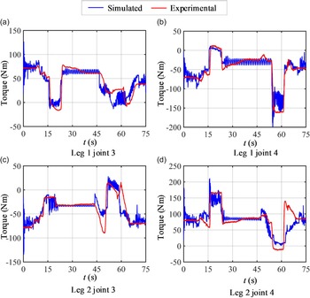
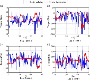
The experiment corresponding to the simulation is performed. In the experimental environment, the rover traverses the same terrain using identical locomotion strategies. The joint torques of both the experiment and the simulation are collected, as shown in Fig. 11. It can be observed that these two curves exhibit the same trend, validating the correctness of the simulation.
Joint torques for stepping over the obstacle in different locomotion strategies. (a) and (b) correspond to joints 3 and 4 of leg 1, respectively. (c) and (d) correspond to joints 3 and 4 of leg 2, respectively.

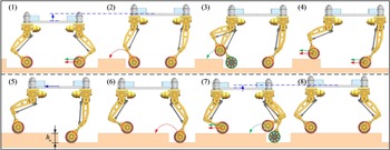
Simulation II is the basic locomotion strategy of climbing upon an obstacle. The height of this platform is 18 cm. Its motion sequence is shown in Fig. 12. From Fig. 12 (1) to (2), wheels 2 and 3 roll forward while lifting the body. Next, two front legs step upon the obstacle successively. The base is shifted forward from Fig. 12 (5) to (6). However, due to the workspace of the front legs, there is only a small stability margin at this time. It will most likely roll over when the last leg leaves the ground. After all the wheels step on the obstacle, the rover adjusts the wheels’ position and lifts the body to return to standard normal driving. The flexibility of the support polygons when wheeled motion is considered allows the rover to traverse uneven terrain more swiftly.
Simulation of climbing on the obstacle.

As comparisons, in the simulated environment, the rover traverses the same terrain using hybrid locomotion and static walking locomotion, respectively. Figure 13 presents the joint torque curves of simulation II obtained from the simulated environment under different locomotion modes. It can be observed that the adoption of hybrid locomotion effectively reduces torque magnitude and diminishes sudden changes in joint torque. Table 3 shows the comparison of energy consumption between the static walking locomotion and the hybrid locomotion. In Simulation I, the energy consumption of the hybrid locomotion is 76.44% lower than that of the static walking locomotion. In Simulation II, hybrid locomotion reduces energy costs by 80.70% compared to static walking locomotion. Moreover, based on the motion generation algorithm, the torque curves of the hybrid locomotion are smooth without abrupt changes.
Joint torques for Simulation II in different locomotion strategies. (a) and (b) correspond to joints 3 and 4 of leg 1, respectively. (c) and (d) correspond to joints 3 and 4 of leg 2, respectively.

5.3. Prototype experiments
Prototype experiments are performed to verify the effectiveness of the proposed locomotion planning framework. Symmetrical and asymmetrical terrains are set in the experimental environments. The TAWL rover is equipped with an Intel RealSense camera to acquire real-time environmental information about its surroundings. This camera is positioned at a 60° angle relative to the body and is primarily used for obstacle recognition in the rover’s forward direction. Visual algorithms are processed by a dedicated onboard computer running on Ubuntu. These algorithms are capable of accurately identifying the location and geometric shape of obstacles. Other sensors like IMU, force sensors, and encoders are connected to the motion control computer via data cables and exchange information with the visual processing computer through wireless communication.
Table 4 shows a comparison of existing methods. To compare the existing hybrid locomotion methods, the TAWL rover is asked to traverse two different types of obstacles similar to the test condition of another wheeled-legged robot, Pholus. Note that the testing data of the robot Pholus comes from the published paper [Reference Sun, You, Zhao, Adiwahono and Chew30]. Even though the TAWL rover’s overall dimension is larger than that of the robot Pholus, it has a smaller maximum base swing amplitude when utilizing the proposed locomotion algorithm.
Repetitive experiments on power consumption.

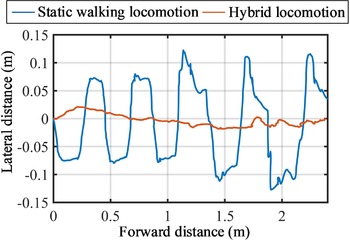
Besides, the static walking locomotion of the TAWL rover is also tested as a comparison. The rover body’s trajectories are shown in Fig. 14. The hybrid locomotion method exhibits a maximum body swing amplitude of 21 mm, whereas the amplitude for static walking locomotion is 126 mm. The swing amplitude is reduced by about 83.3% compared to static walking locomotion. The proposed framework has a clear effect in reducing the lateral movement of the body.
The rover body’s trajectory when crossing the outcrop (obtained from visual odometry).

The rover’s obstacle-crossing ability is also tested using different locomotion algorithms. Using static walking locomotion, the maximum obstacle-crossing height is 18 cm. However, the proposed hybrid locomotion can achieve 25 cm obstacle-crossing height, because the use of wheeled locomotion to adjust the CoM and support triangle makes the support polygon more flexible. In addition, structural interference limits the working space of the CoM during walking locomotion.
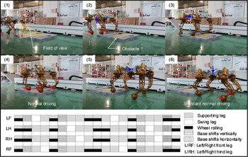
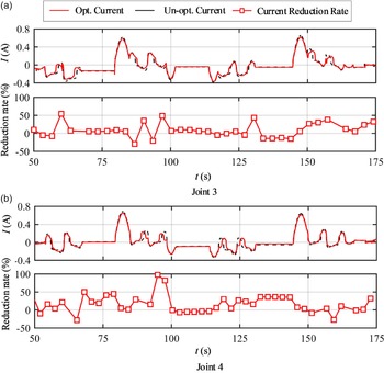
Experiment I verifies the condition of climbing on the symmetrical terrain, as shown in Fig. 15. When both front legs are blocked, the rover exploits the wheeling phase to adjust the support polygon. Then it lifts the front two legs successively. The base is transferred to prepare for the swing phase of the hind legs afterward. When front legs step on the terrain, their wheel centers are relatively close to the body and the hip frame. This leads to the limitation of the workspace. Hence, the range of body motions is limited. The request of no rollover occurs when the last leg steps on the terrain determine the height of the obstacle that the rover can climb. Energy efficiency can be obtained by the motor current shown in Fig. 16. In order to achieve a more direct comparison result, the current offset caused by supporting body weight in the standing position has been removed. Assuming a constant power supply voltage for the motor. The decrease rate in energy efficiency can be represented by the proportion of reduction in current.
 ${}^{i}{I}{}_{\text{ave-opt}}$
and
 ${}^{i}{I}{}_{\text{ave-unopt}}$
represent the average current for leg i with and without optimization, respectively. The average reduction rate
 $R_{e}$
of 4 legs over time period T can be obtained by
 \begin{equation}I_{\mathrm{ave}}=\frac{\sum _{i=1}^{i=4}\left(\int _{t=t_{0}}^{t=T+t_{0}}\left| {}^{i}{I}{}\right| d\boldsymbol{t}\right)}{T}\end{equation}
 \begin{equation}R_{e}=\frac{I_{\text{ave-unopt}}-I_{\text{ave-opt}}}{I_{\text{ave-unopt}}}\end{equation}
Prototype experiment I of crossing the obstacle on both sides. The images above depict the sequential diagrams of this experiment, while the images below illustrate the corresponding gait sequence.

Motor current collected in the experiment. The upper image in (a) displays the optimized and unoptimized current of joint 3, while the lower image shows the proportion by which the current is reduced after optimization. The upper image in (b) displays the optimized and unoptimized current of joint 4, while the lower image shows the proportion by which the current is reduced after optimization.

Multiple repetitive experiments are conducted under different operating conditions to determine the effectiveness of energy conservation. The experimental results are listed in Table 5. Each set of experiments is performed with three repetitions each for both the optimized and unoptimized processes. From the experimental results, it can be observed that in Experiment II, which involves longer distance traveling using wheeled locomotion, the average current is smaller. However, since the optimization is only performed during legged locomotion, the optimization impact in Experiment II is relatively small, resulting in a lesser average reduction rate compared to Experiment I. Generally speaking, in order to achieve the same motion trajectory, the average energy efficiency after optimization is 10.8% lower than that of the unoptimized scenario.
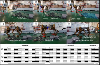
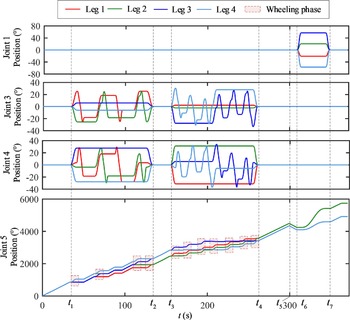
Experiment II verifies the situation of the rover traversing irregular terrains on a single side. In Fig. 17, it first lifts the body and crosses the obstacle on the left side, and returns to standard driving condition after completely passing the first obstacle but before the second one. Gravel on the ground does not cause any hindrance due to the rover’s adaptability. The second obstacle has two stairs. The rover successfully traverses these obstacles while maintaining a good margin of stability. For the third obstacle, the rover recognizes the wooden pillar, retreats for a short distance, and takes a right turn. Figure 18 shows the joint position of each leg. All joints’ motions conform to the velocity and acceleration limits. The height of obstacle 1 is 10 cm, and the two steps of obstacle 2 are 10 cm and 20 cm, respectively. Gait graph depicted in Fig. 17 shows that the rover is able to autonomously choose appropriate hybrid gaits when facing different obstacle environments.
Prototype experiment II of crossing obstacles on a single side. The images above depict the sequential diagrams of this experiment, while the images below illustrate the corresponding gait sequence.

Joint position of experiment II. At time t1–t2, the rover crosses the first obstacle. At time t3–t4, the rover crosses the second obstacle. At time t5, the rover detects the obstacle that needs to be avoided. Due to the limitation of the turning radius, the rover moves backward from t5–t6 and then maneuvers to avoid the obstacle from t6–t7.

6. Conclusions
In this paper, kinematics modeling and hybrid locomotion generation framework for wheeled-legged rovers are proposed. In the harsh environment of planetary exploration, it is an important scientific issue to fully utilize rovers’ capabilities. Improved versatility of wheeled-legged rovers increases control complexity. Therefore, an accurate kinematic model is derived to mathematically describe the kinematic relationship of the mechanisms. Besides, wheel-ground contact is modeled to maintain motion consistency between the wheel and the end-effector. The rover generates proper gaits based on the proposed locomotion planning framework, kinematic ability, and environmental information. The hybrid locomotion strategy models complex gait patterns into a logical framework. Two basic strategies are presented and analyzed, from which variant gait graphs with more complex cycles can be derived. With the planned trajectories, B-splines are utilized to generate joint motions. An optimization equation is applied to minimize the motors’ energy dissipation.
In the prototype experiments, symmetrical and asymmetrical terrains are both tested. Cluttered obstacles make the experiments difficult. However, results show that the rover is able to identify the obstacles and choose the appropriate hybrid gaits to traverse. The proposed framework shows its effectiveness in improving rover flexibility and maneuverability.
Authors’ contributions
Z. B. developed the theory and took the lead in writing the manuscript. Z. B. and S. J. performed the experiments. J.H. supervised the project. All authors have read and agreed to the published version of the manuscript.
Authors’ information
Bike Zhu received the B.S. degree in mechanical engineering in 2019 from the School of Mechanical Engineering, Dalian University of Technology, Dalian, China. She is currently working toward the Ph.D. degree in mechanical engineering with the School of Mechanical Engineering, Shanghai Jiao Tong University, Shanghai, China. Her research interests include visual navigation and motion control of wheeled-legged robots.
Jun He received his Ph.D. degree from the School of Mechanical Engineering, Shanghai Jiao Tong University. He is currently a Professor at the School of Mechanical Engineering, Shanghai Jiao Tong University. His research interests include mechanisms and robotics in space. As a Project Leader, he was engaged in the National Natural Science Foundation of China, etc.
Jiaze Sun received the B.S. degree in mechanical engineering in 2020 from the School of Mechanical Engineering, Shanghai Jiao Tong University, Shanghai, China, where he is currently working toward the Graduate degree in mechanical engineering with the School of Mechanical Engineering. His research interests include design and control of the planetary rover.
Competing interests
The authors declare no competing financial interests.
Acknowledgments
Not applicable.
Funding
This research was funded by the National Natural Science Foundation of China under Grant 52175022.
Appendix
Abbreviations used in this paper and their corresponding meanings: