


1. INTRODUCTION
Stimulated Brillouin scattering (SBS) optical phase conjugation (OPC), a technique with profound significance to high-power laser science, has been studied and made great efforts to application practically by researchers all over the world for decades (Zel'dovich et al., Reference Zel'dovich, Popovichev, Ragul'skii and Faizyllov1972; Basov & Zubarev, Reference Basov and Zubarev1979; Meister et al., Reference Meister, Riesbeck and Eichler2007; Ostermeyer et al., Reference Ostermeyer and Kong2008). In demand for large laser engineerings such as inertial confinement fusion and inertial fusion energy, works on SBS phase conjugator, SBS beam combiner, and so on, are being carried out by more and more research teams (Kong et al., Reference Kong, Lee and Lee2005, Reference Kong, Yoon, Shin, Beak and Lee2006, Reference Kong, Yoon, Beak, Shin, Lee and Lee2007, Reference Kong, Yoon, Shin and Beak2008, Reference Kong, Shin, Yoon and Beak2009; Kappe et al., Reference Kappe, Strasser and Ostermeyer2007; Hasi et al., Reference Hasi, Lu, Li and He2007, Reference Hasi, Gong, Lu, Lin, He and Fan2008; Wang et al., Reference Wang, Lu, Lin, Ding and Jiang2007, Reference Wang, Lu, He, Zheng and Zhao2009; Yoshida et al., Reference Yoshida, Fujita, Nakatsuka, Ueda and Fujinoki2007). As well known, advantages of the SBS phase conjugator are high energy-conversion efficiency and simple structure. However, the acoustic wave, which plays a crucial role in SBS process, is developed from the noise in Brillouin medium (Boyd et al., Reference Boyd, Rzazewski and Narum1990), which makes the phase-conjugate wave instable in many situations. For instance, phase jumps or intensity modulations are frequently observed in experiments (Shahraam et al., Reference Shahraam, Vladimyros and Jesper1998; Yang et al., Reference Yang, Yang, Ding, Li, Zhang and Mang2001), and when the leading-edge of the laser pulse is shorter than or comparable with the phonon lifetime of the Brillouin medium, SBS phase-conjugate fidelity and its stability will deteriorate severely (Dane et al., Reference Dane, Neuman and Hackel1992), which keeps this technique far away from applications of short pulse such as fast ignition laser pulse. Besides, the Stokes wave competes with optical noise modes throughout its generation and amplification processes, leading to the existence of non-conjugate components of the output wave, that is to say, the phase-conjugate fidelity can never really achieve 100% (Zeldovich et al., Reference Zel'dovich, Pilipetskii and Shkunov1982). So far as it goes, problems mentioned above, whose root is the noise-origin characteristic of the acoustic wave, have become severe limiting factors for practical application of SBS phase conjugator.
There is another OPC technique, called Brillouin-enhanced four-wave mixing (BEFWM), which is also based on acousto-optic interaction, but different from SBS in acoustic origin mechanism in nature (Scott & Ridley, Reference Scott and Ridley1989). In BEFWM process, acoustic wave is driven by optical coherent beating patterns and built up instantaneously without acoustic-relaxation-time restriction of the medium. This non-noise process not only keeps OPC stable and transient-state-adaptable but also exhibits advantages as non-threshold and a 100% conjugate fidelity. In the past decades, researches on BEFWM mainly focused on the conjugate-amplification of weak optical signals, and have gain many achievements (Andreev et al., Reference Andreev, Bespalov and Dvoretsky1989; Lanzerotti et al., Reference Lanzerotti, Schirmer and Gaeta1996; Zhu et al., Reference Zhu, Lu, He, Ba, Wang, Gao and Dong2007). However, when BEFWM operates with large incident signals as a high-power phase conjugator, its efficiency, i.e., total reflectivity, will be low because the energy of the conjugate wave comes from the reference wave instead of the signal wave itself (Zhu et al., Reference Zhu, Lu, He, Guan and Xu2008).
In this paper, a composite phase conjugator scheme, in which mechanism of BEFWM and SBS are combined in a compact structure is reported. The BEFWM provides phase-conjugate wave seed with fast response, high quality and stability, which is then magnified by stimulated Brillouin amplification (SBA) with high energy-conversion efficiency. As a result, advantages of BEFWM and SBS can be realized at the same time. In the following sections, the theoretical model is set up, as well as numerical simulations, and demo experiments are carried out. Feasibility of the BEFWM-SBA phase conjugator is verified sufficiently.
2. THEORY
2.1. Physical Model
Physical model of the BEFWM-SBA composite phase conjugator is shown in Figure 1. E 1 and E 2, in Figure 1a, are counter-propagating reference waves, while E 2 has a relative Stokes-shift in frequency. The laser signal wave E 3, as the main laser wave whose power is much greater than the reference waves, intersects E 1 at a small angle, and its conjugate wave generated by the phase conjugator is termed as E 4. All the input waves should be linearly polarized, among which E 1 is in p-polarized-state, E 2 is in s-state, and let the polarized direction of E 3 be slanted slightly, so as to share its power in s-state for a little and most of them be contained in p-state.
Physical model of the composite-mechanism phase conjugator scheme.
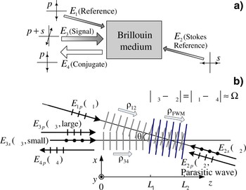
In order to describe these polarization states more explicit, we add letters p and s to the wave notations in Figure 1b, and term the two polarized components of E 3 as E 3p and E 3s separately. The physical picture of interaction among these waves can be depicted as follows: when encounterring in the Brillouin medium, s-state E 3s and E 2s interfere with each other and drive the periodic density variations in the medium that travels from left to right at a velocity close to the velocity of sound in the medium, thus an acoustic wave ρFWM with frequency Ω is produced as a result. ρFWM acts as a moving Bragg-phase grating, once founded, it will scatter E 1p and generate the p-state Stokes-shifted wave E 4p, which is phase conjugated with the laser signal E 3. Then, as E 4p propagates opposite to the way of E 3, it will be Brillouin-amplified by E 3p which is also in the p polarized direction, and high efficiency power growth can be realized.
There are two procedures existing in this scheme. At first, a phase conjugate wave seed is generated through Stokes-type polarization-decoupled BEFWM. Then, growth of the conjugate wave mainly depends on the SBA process. The former process provides characteristics for E 4 as high stability and fidelity, the later one ensures high conversion efficiency. In this way, advantages of BEFWM and SBS can be realized in the composite phase conjugator at the same time.
However, when ρFWM is built, waves in all polarized states will be scattered by it immediately. According to the propagating direction of ρFWM, the signal component E 3p might be Stokes-scattered by ρFWM and generate a Stokes-shifted wave E 2p, which is conjugated with E 1p. We call E 2p a parasitic wave. Here come two harmful effects from the parasitic wave. First, power in E 3p will be lost partly, resulting in decrease of the Brillouin amplification gain of E 4p. Second, E 2p will be Brillouin amplified by E 1p and therefore reduce the E 1p power that should be transported into E 4p through BEFWM process. So, how to ensure that E 4p have the dominance over E 2p during all the processes of generation and amplification is an important issue for this conjugator scheme.
2.2. Mathematical Model
In the following mathematical model, the acoustic waves of SBA in two different directions, i.e., E 3pversus E 4p and E 1pversus E 2p, are denoted as ρ34 and ρ12, respectively, which propagate from left to right too. All of the six optical waves can be described by Maxwell's wave equations, and the three acoustic waves can be depicted by Navier-Stokes's energy transmission equation. Taking the interaction geometry into account as shown in Figure 1b, and based on the assumption of neglecting in the second derivations, the nonlinear coupled-equations describing all the processes mentioned above along the z direction can be written as







and

where E and ρ are amplitudes of optical and acoustic wave, respectively; c is light velocity in the vacuum; n denotes the refractive index; g a(θ) is the acoustic coupling coefficient with the angle θ between the optical waves, and numerically equals to g acos2(θ/2) (Aschroeder et al., Reference Aschroeder, Damzen and Hutchinson1989), in which g a is the value for θ = 0; ΓB is the Brillouin linewidth of the medium; ΔΩ = Ω(cos(θ/2)−1) and Δk = (Δ )z = nΩ(cos θ−1)/c represent, respectively, the frequency detuning and the phase mismatch of acoustic waves in BEFWM; α is the optical absorption coefficient. Compared with the light velocity, the sound velocity is so small that the propagation terms have been neglected in the three acoustic waves, Eqs. (7–9).
According to Figure 1b, E 1p, E 3p, and E 3s are injected at z = 0 while E 2s at z = L 2. E 4p and E 2p equal to zero at z = L 2 or when t = 0. Intensities of other optical waves will be specified as demand. Interaction length of BEFWM is limited between L 1 and L 2, and where out of this range, the gain of BEFWM equals to zero. Brillouin amplifications exist in the entire space 0 ~ L 2 along the propagation directions of E 1 and E 3. So far, all the boundary and initial conditions of the equations are defined, and the numerical simulation can be carried out.
2.3. Simulation and Analysis
In the numerical simulation, the laser signal is chosen as 1.06-µm wavelength and 20-ns full width at half maximum Gaussian pulses. CS2 is chosen as the Brillouin medium (Hasi et al., Reference Hasi, Lu, He and Wang2005), whose n = 1.59, SBS gain coefficient is 68 cm/GW, the phonon lifetime is 6.4 ns, and α = 4 × 10⁻³cm−1. Besides, we set the parameters as: L 1 = 35 cm, L 2 = 50 cm, θ = 10 mrad, the peak intensity ratio of the reference waves is |E 1p|2 : |E 2s|2 = I 1p : I 2s = 2, and the peak intensity ratio of the two polarization components in the signal E 3 is |E 3p|2 : |E 3s|2 = I 3p : I 3s = 20:1.
As mentioned above, suppression of the parasitic wave E 2p is important. An effective method to realize it is to decrease I 1p comparing with I 3p, i.e., to decrease the pumping intensity in the SBA process of the parasitic wave E 2p, so as to decrease the energy extraction ratio for E 2p from E 1p. To do this, although the initial intensity of E 4p generated in BEFWM will be weaker, it can be amplified to become a considerable magnitude by the high-intensity pump wave E 3p in the following SBA process. In Figure 2a, the simulating input pulse waveforms of E 1p, E 3p, and the output waveforms of E 4p and E 2p are shown in the same intensity scale when the injected peak intensities I 3p = 50 MW/cm2 and I 3p = 5 MW/cm2. It is easy to demonstrate that the output E 2p is rather weak.
Numerical simulation on the input and output waveforms of the conjugator when the incident peak power I 3P = 50 MW/cm2, I 1P = 5 MW/cm2, without signal delay (a), and with 20-ns signal delay (b).

Another method helping to suppress the E 2p pulse is to set injecting temporal delay for E 3 relative to E 1 pulse, through which, when E 3 arrives in the BEFWM region and E 2p is generated, there is only a tail part of the E 1p pulse to provide energy transfering to E 2p in the SBA process, which is very limited in energy and actuation duration. Nevertheless, if only the conjugate wave seed E 4p is generated, even though its duration of generation is short and intensity is weak, it can be amplified during the whole subsequent signal pulse span with a high gain. In Figure 2b, it is set as I 1p = 5 MW/cm2, I 1p = 50 MW/cm2, and E 3 is delayed by 20 ns relative to E 1. It can be seen that peak intensity of the conjugate pulse E 4p is close to 50 MW/cm2, while E 2p can almost be neglected.
Other parameter-contributions to the composite PC have been calculated numerically in our theoretical simulation work, and feasibility of this composite-mechanism scheme is verifed in the theory. Performance of the PC, such as reflectivity will be discussed in the next section.
3. EXPERIMENTS
3.1. Experimental Setup
The experimental setup is shown in Figure 3. The Nd:YLF single frequency TEM00 Q-switched laser, operating at 1-Hz repetition rate, can deliver about 120 mJ p-polarized-state pulses at 1053 nm in a 20-ns full width at half maximum quasi-Gaussian pulse shape. The beam diameter is about 4 mm. A λ/2 plate and polarizer P 1 are used to split the laser beam into E 1 wave, i.e., E 1p, and E 3 wave. After passing through the 4% sampling plate SP1 and the polarizer P 4, E 1p enters the 80-cm-length composite cell filled with CS2, i.e., Cell-1, and the forepart of E 1p pulse that transmitted throughout of Cell-1 generates backward Stokes wave in a short-focused-type SBS CS2 cell, i.e., Cell-2, whose lens focus equals to 10 cm and distance from Cell-1 is about 70 cm. When passing backward through the λ/4 plate, the Stokes wave is changed into s-polarized state, then enters into the back window of Cell-1, and acts as E 2s. The E 3 wave, which is reflected by the polarizer P 1 and then by P 2 turns into p-polarized state by a 45° rotor and a 45° Farady rotator, and penetrates through the polarizer P 3 entirely. Then it is adjusted by a λ/2 plate to contain a small s-state component with ratio of I 3p/I 3s = 20, and coupled by 20-ns delay mirrors M 1 ~ M 6 into Cell-1 where BEFWM-SBA process is built up. The angle between E 1 and E 3 is about 10 mrad. The penetrated part of E 3 is obstructed by a diaphragm set behind Cell-1. The conjugate wave E 4p generated in Cell-1 propagates backward along the way of E 3, and finaly penetrates P 2 to become the output wave. The residual E 2s and the parasite wave E 2p will propagate backward along the way of E 1. E 2s will be reflected off by the polarizer P 4, and E 2p can be blocked by the isolator.
Experimental setup of the BEFWM-SBA phase conjugator in demo-version.

In the experiments, we recorded the injection E 1p and the output of E 2p on the two sides of SP1, and recorded E 3 and E 4p on SP2 simultaneously. In order to simulate high-flux laser system, a long focus lens with f = 300 cm is inserted in the path of E 3 to increase the signal intensity to a certian extent in the BEFWM-SBA region, while the focus of the 300-cm lens is located out of the Cell-1 in order to avoid self-excitational SBS of E 3.
3.2. Results and Discussion
Pulsed waveforms and near-field intensity patterns of the input signal E 3 and the output conjugate wave E 4 measured in experiments are shown in Figure 4. A little step, which is usually observed in the Brillouin amplification process, is shown at the root of E 4 waveform. Consistency of the in and out beam cross-sectional patterns is achieved well.
(Color online) Pulsed waveforms and near-field intensity patterns of the input signal wave E 3 and the output conjugate wave E 4.

In order to research the performance of the composite phase conjugator with different laser signal power, in the experiments, we fixed the incident E 1 at 8 mJ/pulse, and varied E 3 from 6 mJ/pulse to about 82 mJ/pulse gradually by changing the applied voltages charged on the Xe-lamps of the Nd:YLF laser. It is shown that the output E 4 increases from about 3 mJ/pulse to about 61 mJ/pulse, while the parasitic E 2p is kept in a range between about 3 mJ/pulse and 6 mJ/pulse, as shown in Figure 5.
Output pulse energies of E 4 and E 2P with different incident laser signal E 3.

Reflectivity R of the composite phase conjugator is defined as energy ratio of E 4 and E 3 pulses, i.e., R = E 4/E 3, which have been measured synchronously using the two same calorimeters at both sides of the sampling plate SP2. For each measuring point, we recorded pulse energies continuously for 60 shots, and analyzed the mean value of R and its shot-to-shot fluctuations. In the discussion about, the stability of the conjugator, fluctuations of the laser itself should be taken into account, because variations in the signal can induce the change of R correspondingly. We note the relative instability of R with the symbol β, and calculate it by

where the symbol with bar on the head is the mean value at a certain measuring point, and Δ denotes the standard deviation, i.e., root mean square. Figure 6a shows the experimental results of R which is as a function of E 3. The increase of E 3 induced the growth of R from 55% to a saturation value about 75%. β is shown in Figure 6b. It is seen that β is almost fixed within the range close to or below 1% during the whole variation of E 3 and at any R values, which demonstrates a very good stability.
Reflectivity R (a) and its relative instability β (b) with different incident laser signal E 3.

In Figure 6a, the theoretical result is shown as a solid line. Although the tendency of which is in accordance with the experiments, it is seen obviously that the deviation occurs when E 3 is larger. In our analysis, it is attributed to incomplete polarization control for the injecting optical waves.
Far-field divergence angles of the output conjugate wave E 4 is recorded by an array camera, the result is shown in Figure 7. When the signal increases, the mean value of the divergence angles of E 4 is about 0.451 mrad, which is close to the signal divergence 0.434 mrad. In addition, the fluctuation of the output divergence angles is below 5% in the whole experimental signal range.
Far-field divergence angles of the output conjugate wave E 4 with different incident laser signal E 3.

4. CONCLUSIONS
A novel BEFWM-SBA composite phase conjugator can be realized by polarization control in a compact interaction region, in which generation and amplification of the phase conjugate wave operates in BEFWM and SBA process, respectively. In this way, the advantages coming from non-noise origin of the acoustic wave and high-efficiency coupling can be achieved simultaneously very well, such as rapid response, high conjugate fidelity, high stability, and high efficiency.
Feasibility of this BEFWM-SBA mechanism is verified by the theoretical simulations and the experiments. Because almost all of the parameters are required adjustable in the demo-version experimental layout, it is seen rather complex in the structure, and a simplified version should be employed in the practical applications. For the experimental results in this paper, it is estimated that the incomplete control of the polarization states is the prime reason resulting in deviations of the experimental results from that of the theory. Besides, the output performance, such as a conjugation fidelity, which can be indicated by the far-field divergence angle, could be influenced by so many optical elements in the experimental setup.
Significant potential performance characteristics of the composite conjugator which will be very interesting are worth to be verified and studied in the following work. For instance, the transient-state adaptabitility supported by non-noise origin of the acoustic wave, the high repeat rate laser pulses, and the high-power laser-load adaptabitility because of the non-focus structure of the composite interaction region, and so on.
ACKNOWLEDGEMENTS
This work is supported by the National Natural Science Foundation of China (Grant No. 60878005), the National High Technology Development Program of China and the Program of Excellent Team in Harbin Institute of Technology. One of the authors, Cheng Yu Zhu, wishes to thank Professor Hong Jin Kong (Department of Physics, Korea Advanced Institute of Science and Technology) for his help in preparation of this paper.



