NOMENCLATURE
- CAEP
-
Committee on Aviation Environmental Protection
- CFD
-
Computational Fluid Dynamics
- FAR
-
Fuel-Air-Ratio
- ICAO
-
International Civil Aviation Organization
- LDI
-
Lean Direct Injection
- LPP
-
lean-burn premix prevaporised
- LTO
-
Landing and Take-Off
- MLDI
-
Multi-Point Lean Direct Injection
- NASA
-
National Aeronautics and Space Administration
- RQL
-
Rich-burn, Quick-quench, Lean-burn
- TAPS
-
Twin Annular Premixing Swirler
- TRL
-
Technology Readiness Levels
- A
-
area (m2)
- AR
-
area ratio
- Cp
-
real pressure recovery coefficient
- Cpi
-
ideal pressure recovery coefficient
- D
-
diameter (m)
- Dp
-
The mass of any gaseous pollutant emitted during the reference emissions landing and take-off cycle (g)
- EI
-
emission index (g/kg of fuel)
- F00
-
rated thrust of the engine (kN)
- Gm
-
axial flux of angular momentum
- Gt
-
axial thrust
- HE
-
height (m)
- J
-
momentum-flux ratio
- K
-
swirler coefficient
- LW
-
length-to-width ratio
- M
-
Mach number
- N, n
-
number
- NOx
-
nitrogen oxides
- P
-
total pressure (kPa)
- PR
-
pressure ratio
- SN
-
swirl number
- T
-
total temperature (°K)
- TET
-
turbine entry temperature (°K)
- V
-
velocity (m/s)
- W
-
mass flow (kg/s)
- Y
-
penetration of jets (m)
- ΔP/P
-
pressure loss
- η
-
combustion efficiency
- Φ
-
equivalence ratio
- ε
-
cooling effectiveness
- μ
-
fraction of air
- γ
-
isentropic coefficient
- ρ
-
density (kg/m3)
- θdif
-
theta parameter
-
diffuser divergence half angle (°)
- 3
-
combustor inlet
- 31
-
diffuser inlet, excluding bleeding air
- 4
-
combustor outlet
- a
-
air
- at
-
atomising
- b
-
burn
- c
-
coolant, cooling
- d
-
dome
- dc
-
dome cooling
- dd
-
dump diffuser
- dif
-
diffuser
- dil
-
dilution
- dil-cs
-
cross-section of dilution holes
- f
-
fuel
- g
-
gas
- hub
-
swirler hub
- j
-
jet
- L
-
liner
- lc
-
liner cooling
- lcpz
-
liner cooling in primary zone
- m
-
metal
- m1,2,3
-
injector main1, main2 and main3
- p
-
passage
- pd
-
pre-diffuser
- pilot
-
pilot injector
- pitch
-
pitch point
- pj
-
primary jets
- pz
-
primary zone
- ref
-
reference
- stoi
-
stoichiometric condition
- sw
-
swirler
- wind
-
windmilling condition
Abbreviations
Notations
Subscripts
1.0 INTRODUCTION
In the past four decades, more stringent regulations on aircraft NOx emission during Landing and Take-Off (LTO) cycle have been imposed by the International Civil Aviation Organisation (ICAO) due to its effect on the local air quality at low altitude(Reference Foust, Thomsen, Stickles, Cooper and Dodds1). Another way that NOx can damage the environment is through its influence on the ozone layer depletion during cruise at high altitude, although no legislation regarding this has been applied so far. Meanwhile, continuous elevation in engine overall pressure ratio and turbine entry temperature (TET) due to increased performance requirements further contribute to the formation of NOx. Combustors which not only satisfy ICAO LTO NOx emissions regulations but are also able to achieve high efficiency and low Specific Fuel Consumption are in high demand. Low-emission technologies such as Rich-burn, Quick-quench, Lean-burn (RQL) have been developed and proved successful. The Lean Direct Injection (LDI) is one of the concepts which utilises lean combustion to limit NOx formation by lowering the flame temperature. Compared to other low emission combustors, the LDI is shorter in length and capable of achieving further reduction in NOx relative to RQL combustor. It is less likely to suffer from combustion instabilities and flashback than the Lean Premixed Prevaporised (LPP) combustor. However, current research including those by the National Aeronautics and Space Administration (NASA) and Rolls-Royce have only reached Technology Readiness Levels (TRLs) of up to 6 and 4, respectively(Reference Colantuoni2,Reference Reddy and Lee3) . Neither in-service engine application has been achieved, nor have design methodologies been published. Another lean burn combustor called Twin Annular Premixing Swirler (TAPS) has reached TRL9 and applied on GEnx engines for Boeing B747-8 and B787 since 2011. It incorporates a pilot stage with diffusion flame and partially premixed main-stage injectors positioned radially outwardly of the pilot. However, detailed reviews and comparisons between these technologies are beyond the scope of this paper as it mainly focuses on the design methodology of a NASA LDI-2 combustor, more references on TAPS combustor can be found in Fauset et al(Reference Foust, Thomsen, Stickles, Cooper and Dodds1) and Mongia et al(Reference Mongia4). Computational Fluid Dynamics (CFD) is widely used throughout the combustor design process, while its consumption in time and computational power may not be affordable or economical at the early design stage where limited information is available. The need is clear for the development of an LDI combustor design method that provides the best compromise between time and accuracy as well as useful information for higher-fidelity simulations.
The LDI combustor takes advantage of lean combustion, the flame temperature of which is decreased by burning the fuel away from the stoichiometric condition. Instead of being prevaporised and premixed with air, the fuel is directly injected into the flame zone. Hence, LDI combustors are less prone to auto-ignition and flashback than LPP combustors. The fuel injector design is therefore critical for LDI combustors since good atomisation and homogeneous fuel-air mixing should be guaranteed.
Two types of LDI combustors have been developed: the Rolls-Royce LDI(Reference Klinger, Lazik and Wunderlich5) and NASA's multi-point LDI (MLDI) concept(Reference Tacina, Mao and Wey6). The RR LDI is similar to the TAPS concept, which features an internally staged SAC architecture. The centre pilot and surrounding main stages are separated by a splitter which creates a wake called a bifurcated flow field leading to the pilot and main flames. The RR LDI combustor is reported to demonstrate an NOx reduction of 60% relative to the Committee on Aviation Environmental Protection (CAEP)/6 standard at TRL6 for an engine with a pressure ratio of 39. Unlike the scenario with the RR LDI having a larger fuel injector, the idea of the NASA MLDI is to divide the combustor dome into arrays of small injectors in order to achieve uniform fuel-air mixing across the dome area. There are two generations of MLDI combustors: LDI-1 and LDI-2. The dome of the LDI-1 is composed of many identical fuel injectors, whereas fuel staging is applied in the structure of LDI-2 injectors, which allows further reduction of NOx and wider operating range. The LDI-2 can be further categorised into three concepts developed by Parker Hannifin Corp., Goodrich Corp. and Woodward FST, respectively. The LDI-2 Woodward concept is selected for this study since it has better operability at low power settings than the LDI-1. The number of injectors is also smaller compared to other concepts, thus reducing the complexity and cost of the system. The dome of a flat-dome LDI-2 Woodward combustor is shown in Fig. 1. A large pilot injector is located in the centre of the matrix, surrounded by main injectors called main1, main2 and main3. Each of the main injectors has four identical configurations. Table 1 provides details on fuel injectors and swirlers. The fuel stage zones are fed by three fuel lines with main2 and main3 sharing the same supply. A reduction of up to 87–88% on the CAEP/6 standard can be achieved according to the experiment with Woodward's configuration(Reference Tacina, Chang, He, Lee, Dam and Mongia7). The fuel and air staging at different power settings are apparently critical to the performance and emission of the LDI-2 combustor, which is the focus of this paper.
LDI-2 combustion concept (Woodward)(Reference Tacina, Chang, He, Lee, Dam and Mongia7).

Second generation of NASA MLDI configurations by Woodward FST(Reference Tacina, Chang, He, Lee, Dam and Mongia7); cw, clockwise; ccw, counter clockwise.

2.0 METHODOLOGY
In the early stages of combustor design, the procedure usually follows the routine shown in Fig. 2. Given the combustor inlet and outlet conditions along with the architecture as the input, the amount of air partitioned into each zone is then determined. The size of the combustor and its components is calculated based on air partitioning. Although not included in the current research, the fuel injection system must also be developed to provide information such as spray cone angle and Sauter Mean Diameter. It is noteworthy that some of the correlations applied in this paper may be outdated due to limited information in the public domain and should therefore be treated with caution. Specific notes will be addressed when these correlations are used.
Combustor preliminary design procedure.

The preliminary design is evaluated by various operational and performance criteria and adjusted according to evaluation feedback. Sensitivity studies are conducted to investigate design and model uncertainties. The preliminary design results can be optimised by employing multidisciplinary design optimisation (MDO) to further fulfil the often-conflicting requirements. As more requirements such as cooling, stability and size are met during development and optimisation, the emission performance will be compromised. Consequently, the emission production increases for more mature technologies with higher TRLs.
2.1 Assumptions
For this study, Jet-A with a chemical formula of C12H23.5 is selected as the fuel. Constant gas properties are applied to simplify the preliminary design process. The difference between the constant and variable gas properties in the design outcome is discussed in the sensitivity study. The flow coefficient is assumed to be unity for the design of liner holes and swirlers.
2.2 Air distribution
The configuration of an LDI combustor differs from that of a conventional combustor, so the air distribution method of Mellor(Reference Mellor8) and Mattingly(Reference Mattingly9) were combined along with specific consideration for LDI combustors. In an LDI combustor, only the primary and dilution zones exist; primary holes are cancelled, causing a majority of the air to enter from the dome.
The equivalence ratio of the primary zone is firstly determined. To calculate the flame temperature, Mattingly's(Reference Mattingly9) method is no longer suitable for Φ above unity. Walsh and Fletcher's(Reference Walsh and Fletcher10) correlations summarising a large amount of experimental data on kerosene are applied. They are expressed as follows:
 $$\begin{equation}
{\rm{FA}}{{\rm{R}}_1} = 0.10118 + 2.00376 {\times}{10^{ - 5}} {\times}\left( {700 - {T_3}} \right)
\end{equation}$$\\
 $$\begin{equation}
{\rm{FA}}{{\rm{R}}_2} = 23.7078 {\times}{10^{ - 3}} - 5.2368 {\times}{10^{ - 6}} {\times}\left( {700 - {T_3}} \right) - 5.2632 {\times}{10^{ - 6}} {\times}{T_g}
\end{equation}$$\\
 $$\begin{equation}
{\rm{FA}}{{\rm{R}}_3} = 8.889 {\times}{10^{ - 8}} {\times}\left| {{T_g} - 950} \right|
\end{equation}$$ \\
 $$\begin{equation}
{\rm{FAR}} = \left( {{\rm{FA}}{{\rm{R}}_1} - \sqrt {{\rm{FAR}}_1^2 + {\rm{FA}}{{\rm{R}}_2}} - {\rm{FA}}{{\rm{R}}_3}} \right)/{\eta _b}
\end{equation}$$
The flame temperature can be derived from the equations above with several iterative calculations. A correction coefficient Fuel-Air-Ratio (FAR)stoi/FAR is applied in the gas temperature if FAR exceeds FARstoi. The liner cooling air partitioning is calculated by Mattingly's method with cooling effectiveness and the fraction of cooling air required defined as
 $$\begin{equation}
\varepsilon = \frac{{{T_g} - {T_m}}}{{{T_g} - {T_c}}}
\end{equation}$$\\
 $$\begin{equation}
{\mu _c} = \frac{\varepsilon }{{25 {\times}\left( {1 - \varepsilon } \right)}}\ \;{\rm{transpiration}}{/}{\textrm{e{ff}usion}}\;{\rm{cooling}}
\end{equation}$$
2.3 Sizing
The velocity method was chosen to determine reference parameters of the combustor and the theta parameter method was utilised to verify if the design is satisfactory at windmilling conditions (altitude relight capability). Typical values of dome and passage velocities are shown in Table 2.
Typical dome and passage reference velocities(Reference Mellor8)

They can be slightly adjusted for the LDI combustor in order to satisfy performance and size requirement. The dome and passage area Ad and Ap can then be calculated by
 $$\begin{equation}
{A_d} = \frac{{{W_d}}}{{{\rho _3}{V_d}}}
\end{equation}$$ \\
 $$\begin{equation}
{A_p} = \frac{{{W_p}}}{{{\rho _3}{V_p}}}
\end{equation}$$
 $$\begin{equation}
{A_{{\rm{ref}}}} = {A_d} + {A_p}
\end{equation}$$\\
 $$\begin{equation}
{V_{{\rm{ref}}}} = \frac{{{W_3}}}{{{\rho _3}{A_{{\rm{ref}}}}}}
\end{equation}$$
The calculation and verification of theta parameters at windmilling conditions are identical with those described in Zhao(Reference Zhao11), where the theta parameter curve for conventional combustors with stoichiometric primary zone is employed due to lack of data for RQL combustors. According to the theta curve in Ref. Reference Lefebvre12 (see Fig. 4), for lean primary zone combustors, lower combustion efficiency is expected for the same value of theta when compared with conventional combustors. The calculated combustion efficiency for the LDI combustor in this study may be over predicted.
As illustrated in Fig. 3, the diameter of the pitch point of the reference cross section D ref_pitch can be roughly estimated as 0.5(D 3_pitch+D 4_pitch). The reference and dome heights can then be determined by
 $$\begin{equation}
{\rm{H}}{{\rm{E}}_{{\rm{ref}}}} = \ \frac{{{A_{{\rm{ref}}}}}}{{\pi {D_{{\rm{ref}}\_{\rm{pitch}}}}}}
\end{equation}$$\\
 $$\begin{equation}
{\rm{H}}{{\rm{E}}_{{\rm{dome}}}} = \ \frac{{{A_{{\rm{dome}}}}}}{{\pi {D_{{\rm{ref}}\_{\rm{pitch}}}}}}
\end{equation}$$
Sketch of the combustor.

The combustor liner length should be designed to optimise combustion efficiency and overall weight. The suggested length for a conventional combustor is twice that of the dome height, which is not appropriate since the dome area for LDI combustors is larger due to extra air for lean combustion. It is reasonable to assume that the liner length is equal to the dome height. The number of combustor domes is estimated by
 $$\begin{equation}
{N_d} = \frac{{\pi {D_{{\rm{ref}}\_{\rm{pitch}}}}}}{{{\rm{H}}{{\rm{E}}_{{\rm{ref}}}}}}
\end{equation}$$
2.4 Diffuser
The diffuser of a modern annular combustor is normally composed of a faired pre-diffuser followed by a dump-diffuser for the purpose of reducing air velocity and achieving stable combustion with limited length and pressure loss, commonly 4–6%. This combination is selected for the design of the LDI combustor. The design method used by Mohammed and Jeng(Reference Mohammad and Jeng13) is applied. The area ratio AR, which is the ratio between the area of the outlet and the inlet of the pre-diffuser (A2/A1), ranges between 1.4 and 3.0. The length-to-width ratio can be expressed as follows:
 $$\begin{equation}
{\rm{LW}} = {\left( {\frac{{{\rm{AR}}}}{{1.044}}} \right)^{\frac{1}{{0.38859}}}} - 0.26\quad \quad \left( {{\rm{AR}} < 2} \right)
\end{equation}$$\\
 $$\begin{equation}
{\rm{LW}} = \frac{{44.8535}}{{1 + 2165.67{e^{ - 2.8225{\rm{AR}}}}}}\quad ({\rm{AR}} > 2)
\end{equation}$$
The pre-diffuser divergence half-angle θ is represented by Equation (16) and within the range of 4–8°.
 $$\begin{equation}
{\rm{tan}}\theta = \frac{{{\rm{AR}} - 1}}{{2{\rm{LW}}}}
\end{equation}$$
The ideal and the real pressure recovery coefficient are dependent on AR and LW:
 $$\begin{equation}
{C_{pi}} = 1 - \left( {\frac{1}{{{\rm{A}}{{\rm{R}}^2}}}} \right)
\end{equation}$$\\
 $$\begin{equation}
{C_p} = - 0.918 {\times}\frac{1}{{{\rm{A}}{{\rm{R}}^{0.5}} {\times}{\rm{LW}}}} + 0.677 {\times}\frac{1}{{{\rm{A}}{{\rm{R}}^2} {\times}{\rm{L}}{{\rm{W}}^2}}} + 0.74
\end{equation}$$
The pressure loss for both the pre-diffuser and the dump diffuser are formulated as
 $$\begin{equation}
\frac{{\Delta {P_{pd}}}}{{{P_3}}} = \left( {{C_{pi}} - {C_p}} \right)\left[ {1 - {{\left( {1 + \frac{{\gamma - 1}}{2}M_{31}^2} \right)}^{\frac{{ - \gamma }}{{\gamma - 1}}}}} \right]
\end{equation}$$\\
 $$\begin{equation}
\frac{{\Delta {P_{dd}}}}{{{P_3}}} = \left[ {1 - {{\left( {\frac{{{A_1}}}{{{A_{{\rm{ref}}}}}} {\times}{\rm{AR}}} \right)}^2}} \right]\left[ {1 - {{\left( {1 + \frac{{\gamma - 1}}{2}\frac{{M_{31}^2}}{{{\rm{A}}{{\rm{R}}^2}}}} \right)}^{\frac{{ - \gamma }}{{\gamma - 1}}}}} \right]
\end{equation}$$
The total pressure loss of the diffuser is calculated by
 $$\begin{equation}
\frac{{\Delta {P_{{\rm{dif}}}}}}{{{P_3}}} = 1 - \left( {1 - \frac{{\Delta {P_{pd}}}}{{{P_3}}}} \right)\left( {1 - \frac{{\Delta {P_{dd}}}}{{{P_3}}}} \right)
\end{equation}$$
2.5 Dilution holes
The dilution holes enable the injection of the dilution air to further complete the combustion and tailor the outlet temperature profile. The jet penetration should be sufficient for good mixing in order to produce reasonable RTDF while not extravagant to limit pressure loss. The number and size of the dilution holes can be estimated by the method described in this section. Due to the lack of more recent materials in the calculation of dilution holes, the current method provides only an indicative analysis, as it was developed for technologies decades ago. More research should be conducted to obtain correlations or models applicable to low-emissions combustors.
As shown in Fig. 5, the flow through the liner hole can be described by several parameters. To simplify the design, the jet angle θ is assumed to be 90°.
Effect of primary zone mixture strength on the shape of theta curves(Reference Lefebvre12).

Sketch of flow through liner hole(Reference Lefebvre and Ballal14).

According to Lefebvre(Reference Lefebvre and Ballal14), the penetration of multiple jets can be estimated by
 $$\begin{equation}
{Y_{{\rm{max}}}} = 1.25{D_j}{J^{0.5}}\frac{{{W_g}}}{{{W_g} + {W_j}}}
\end{equation}$$
with Wg and Wj being the mass flow rate of the hot gas and cooling jet, and
 $$\begin{equation}
J = \frac{{{\rho _j}V_j^2}}{{{\rho _g}V_g^2}}
\end{equation}$$
The Cranfield design method,(Reference Lefebvre and Ballal14) which reveals the influence of the aerodynamic blockage caused by jets on the penetration and mixing process, is utilised to obtain the optimum hole number and size. It is suitable for cases with an extremely high value of Wj /Wg . The mass flow rate of the air through the dilution holes is
 $$\begin{equation}
{W_j} = \frac{\pi }{4}nD_j^2{\rho _3}{V_j}
\end{equation}$$
where the jet velocity Vj can be obtained by
 $$\begin{equation}
{V_j} = {\left( {\frac{{2\Delta {P_L}}}{{{\rho _3}}}} \right)^{0.5}}
\end{equation}$$
The number and the diameter of the holes can be represented by
 $$\begin{equation}
nD_j^2 = 15.25{W_j}{\left( {\frac{{{P_3}\Delta {P_L}}}{{{T_3}}}} \right)^{ - 0.5}}
\end{equation}$$
The liner pressure loss can be calculated by subtracting the diffuser pressure loss and hot combustion loss from the specified pressure loss through the combustor. The momentum-flux ratio J should be within the range of 5–105(Reference Mellor8). According to Lefebvre(Reference Lefebvre and Ballal14), it is suggested that for annular combustors, the jet penetration is close to 0.4 HEd; hence, the diameter and the number of the dilution holes are obtained.
2.6 Swirler
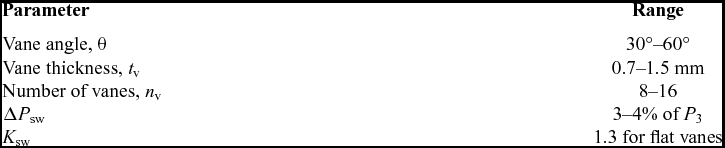
The axial swirler is selected in the research of LDI-2 combustor concept. Therefore, it is chosen for the LDI combustor design in this paper. Both flat-vaned and curved-vaned designs have been used in the research of LDI combustors because of their different advantages. In this paper, the flat vane is chosen for its simplicity and low cost. The design parameters of an axial swirler are shown in Fig. 6.
Definition of axial swirler(Reference Lefebvre and Ballal14).

The calculation is carried out using the following equations:
 $$\begin{equation}
{W_{{\rm{sw}}}} = \sqrt {\frac{{2{\rho _3}\Delta {P_{{\rm{sw}}}}}}{{{K_{{\rm{sw}}}}\left[ {{{\left( {\frac{{{\rm{sec}}\theta }}{{{A_{{\rm{sw}}}}}}} \right)}^2} - \frac{1}{{A_L^2}}} \right]}}}
\end{equation}$$\\
 $$\begin{equation}
{A_{{\rm{sw}}}} = \frac{\pi }{4}\left( {D_{{\rm{sw}}}^2 - D_{{\rm{hub}}}^2} \right) - 0.5{n_v}{t_v}\left( {{D_{{\rm{sw}}}} - {D_{{\rm{hub}}}}} \right)
\end{equation}$$
The swirler pressure loss ΔP sw is assumed to be equal to the liner pressure loss. The vane angle θ is constant for the flat-vaned swirler. The typical values for these parameters are listed in Table 3. The value of D hub is usually slightly larger than the outer diameter of the fuel injector for installation consideration. D sw can be determined based on the information above.
Typical values of axial swirler design(Reference Lefebvre and Ballal14)

According to Beer and Chigier(Reference Béer and Chigier15), the swirler strength is characterised by the swirl number defined in Equation (29).
 $$\begin{equation}
{S_N} = \frac{{2{G_m}}}{{{D_{{\rm{sw}}}}{G_t}}}
\end{equation}$$
where Gm is the axial flux of the angular momentum and Gt is the axial thrust. For a flat-vaned swirler, the swirl number can be simplified as represented in Equation (30) (Reference Lefebvre and Ballal14,Reference Béer and Chigier15) due to difficulties in measuring angular momentum and axial thrust.
 $$\begin{equation}
{S_N} = \frac{{2\left( {1 - {{\left( {\frac{{{D_{{\rm{hub}}}}}}{{{D_{{\rm{sw}}}}}}} \right)}^3}} \right)}}{{3\left( {1 - {{\left( {\frac{{{D_{{\rm{hub}}}}}}{{{D_{{\rm{sw}}}}}}} \right)}^2}} \right)}}{\rm{tan}}\theta
\end{equation}$$
In practical cases, Sn mainly ranges from 0.6–1.5 to generate steady recirculation and prevent the reverse mass flow from exceeding the swirler mass flow(Reference Glass16). For LDI combustors, good mixing is essential for the reduction of NOx, which requires a swirl number of around 0.8–1.0(Reference Lee, Tacina and Wey17–Reference Fu and Jeng20). In this paper, the swirl number is restricted to within 0.6–1.2.
The rotation orientation of adjacent swirlers is another critical factor influencing the mixing process of the LDI combustor, since it contains hundreds of injectors, the essential elements of which are swirlers. In a summary of Yang(Reference Yang, Siow, Peschke and Tacina21), Cai(Reference Cai, Jeng and Tacina19,Reference Cai22) and Fu's(Reference Fu and Jeng20,Reference Fu, Jeng and Tacina23) study, the counter-swirler tends to have better performance and greater turbulence than the co-swirler. It has also been applied in the LDI-2 combustion concept research, so it is therefore is selected here. Finally, the total dimension of the swirlers should not exceed the combustor dome height to prevent installation difficulties.
2.7 Fuel staging
For LDI combustors, only the pilot stage operates at the ground idle condition. As the power setting increases, the main1 stage participates in the combustion for the approach condition. During climb and take-off, all stages are lit. The local equivalence ratio can be defined as Equation (31) with a representing the fraction of the dome cooling air distributed to each stage.
 $$\begin{equation}
{\rm{local}}\;\Phi = \frac{{{W_f}}}{{{W_{{\rm{sw}}}} + a{W_{{\rm{dc}}}}}}
\end{equation}$$
The equivalence ratio at the pilot stage is decided first. The main function of the pilot stage is to stabilise the flame at a low power setting. On one hand, the equivalence ratio at the pilot stage is designed to be above unity to secure sufficient air for main stages and to avoid stoichiometric combustion where the flame temperature is so high that the formation of thermal NOx nears peak value. On the other hand, substantial smoke and even rich extinction could appear as the equivalence ratio continues to rise. A value of 1.2–1.6 is recommended, although it could reach 2.4 in an LDI-2 Goodrich concept test. A sensitivity study was carried out and is presented in Section 4. The fuel staging for main stage injectors is determined afterwards. Care should be taken that the equivalence ratio at each main stage should be similar(Reference Ajmani, Mongia and Lee24) so that homogeneous mixing and combustion can be achieved to prevent local hot spots where a large amount of thermal NOx is likely to be produced. The possibility of weak extinction due to the excessive amount of air should also be eliminated during the calculation.
2.8 NOx correlations for LDI combustors
Tacina et al(Reference Tacina, Chang, He, Lee, Dam and Mongia7) developed correlations predicting NOx emission for second-generation LDI combustors with flat domes, which is the type used in this study. They were based on tests in a flame tube conducted by the NASA Glenn Research Center. It can be seen from Equation (32) that the emission mainly depends on inlet pressure and temperature, pressure loss and equivalence ratio.
 $$\begin{equation}
{\rm{EINO_{x}}} = P_3^{0.50}{e^{\frac{{{T_3}}}{{230}}}}{\left( {\frac{{\Delta P}}{{{P_3}}}} \right)^{ - 0.60}}\left( {0.0081\Phi _{{\rm{pilot}}}^{0.29} + 0.350\Phi _{m1}^{7.15} + 0.369\Phi _{m2,3}^{7.37}} \right)
\end{equation}$$
For the purpose of comparison, the EINOx of the LDI-1 combustor is also calculated by the correlation proposed by Tacina et al(Reference Lee, Tacina and Wey17) multipoint LDI-1 combustors as shown in Equation (33), which could be applied to both high- and medium-pressure situations.
 $$\begin{equation}
{\rm{EINO_{x}}} = 1.359{e^{\frac{{{T_3}}}{{194}}}}{\rm{FA}}{{\rm{R}}^{1.69}}P_3^{0.595}{\left( {\frac{{\Delta P}}{{{P_3}}}} \right)^{ - 0.565}}
\end{equation}$$
2.9 Code structure
The structure of the LDI combustor design codes is shown in Figure 7 for the overall and component sizing including the diffuser, the swirler and liner holes. The fuel staging and NOx emission estimation are also covered.
LDI combustor design codes flow chart.

3.0 CASE STUDY
The preliminary aerodynamic design of an LDI-2 Woodward concept combustor, namely CULDI2015, was conducted for an engine similar to the V2500, renamed as CUTF1. The design outcome is analysed and compared with the V2500 RQL combustor since its structure dimensions and boundary conditions have been used as the input for the CULDI2015 combustor (listed in Tables 4 and 5). The combustor geometric sizes were measured from figures in Hernandez(Reference Hernandez25), while the inlet and outlet conditions at different power settings were obtained from the in-house Cranfield University gas turbine performance simulation tool TURBOMATCH, which have been validated against available data(Reference Zhao11).
Input structure dimensions

Codes input parameters for LTO cycle

The primary zone equivalence ratio is firstly selected with a value of 0.5, leading to a calculated flame temperature of 1,820°K. Such flame temperature sits within the range from 1,670°K to 1,900°K, where both CO and NOx emissions are limited. Besides, a flame temperature of 1,820°K is appropriate for an engine with an overall pressure ratio of 32.74. It can be concluded that the primary zone equivalence ratio is reasonable. Table 6 presents the air distribution in each zone and stage of the LDI combustor. The fraction of the liner cooling air is calculated using Equations (5) and (6) with the assumption that the maximum liner temperature does not exceed 1,100°K. It can be seen that in the designed LDI combustor, 77.9% of the total air mass flow is contained in the primary zone, which is totally different from the case with conventional combustors. The dome cooling air takes up to 15.0% of the total air mass flow, so the dome area is notably larger than that of a conventional combustor.
Combustor air distribution

The fuel staging for the LDI combustor at each of the four power settings is carried out with the aforementioned criteria and listed in Table 7. The fuel allocated to the pilot stage is clearly decreasing as the power setting increases, from 100% at idle condition to 14.9% at maximum power. At high power settings, the fuel is staged in a way that the local equivalence ratio at each stage is similar to avoid inhomogeneous mixing.
Fuel staging in LTO cycle

The velocity method is used for combustor sizing. The dome and passage velocities are 10.2 and 50 m/s, respectively, which is a compromise between enhanced mixing and adequate combustor size and weight. The calculated size parameters are shown in Table 8. It is noted that the reference velocity is 13.1 m/s, which is significantly lower than that of a conventional combustor, resulting in a larger dome area. It can be explained by the fact that the LDI combustor requires significantly more air than the conventional combustor to sustain lean combustion. The liner pressure loss is 3.29%, which is acceptable for the mixing process. A liner length of 0.159 m is also adequate for aero-engine applications. The combustion efficiency at the windmilling condition is checked with a flight altitude of 10 km and a flight Mach number of 0.8. The combustor inlet conditions as displayed in Table 9 are evidently lower than those at the normal conditions, making it more difficult for the fuels to burn efficiently. A value of 4.11e + 07 for the theta parameter is obtained, through which the combustion efficiency is estimated above 80%.
Results of combustor sizing

Combustor inlet parameters of windmilling condition

The diffuser design outcome is shown in Table 10. The designed diffuser shows a pressure loss of 1.21%, which is less than 40% of the compressor outlet velocity head as required. It is also apparent that the dump diffuser loss is the dominant factor in the diffuser pressure loss. Lower dump pressure loss could be achieved at the expense of a longer diffuser.
Results of diffuser design

Table 11 presents the results of the dilution holes parameters determined using the Equations (22)–(26) presented in Section 2.5. There are 54 holes distributed on the inner and outer liner wall, each with a diameter of 11 mm. The cross-section area of the dilution zone is 0.192 m2, smaller than the dome area, indicating a convergent shape of the flame tube in order to achieve good turbulent mixing. The momentum-flux ratio J is 32.9, which is reasonable as it lies in the suggested range of 5–105. It is demonstrated that the jet penetration and the mixing with the main stream gas are expected to be appropriate.
Design results of combustor dilution holes

The number of the domes for the LDI combustor is firstly estimated to be 10 with Equation (13). Then the design of the swirlers at the pilot and each main stage is chosen to be axial swirlers, each equipped with eight 1 mm thick vanes. As shown in Table 1, for the pilot swirler, the vane angle is 55° for the consideration of mixing and operability. The vanes in the main stage swirlers are at 45°. The design parameters of swirlers for each stage are listed in Table 12. The dimension of the entire swirler array is 88.9 mm, which is less than the dome height. The swirl numbers are all above 0.6, revealing sufficiently strong swirl and hence good mixing.
Results of combustor swirler design (each dome)

Having finished the preliminary aerodynamic design of the LDI combustor, it can be observed from Fig. 8 that the total length of the LDI combustor is 18% less than that of the reference RQL combustor V2500 of the current design. The reduction in length makes the LDI more competitive compared to RQL combustor if applied to a newly designed engine, as reduced shaft length is beneficial to the engine rotor dynamics. However, this effect might be cancelled out by the increase in combustor diameter, which may have an impact on engine weight because of increased casing diameter. In the current design, the combustor reference sizes are slightly increased (<10%) compared to those of the V2500 RQL combustor cited by Zhao(Reference Zhao11) despite having a larger dome height.
Comparison between design result and reference combustor.

As the primary interest of the LDI combustor is its relatively low NOx emissions, it is necessary to assess the NOx emission level of the designed combustor. The NOx emission correlation in Equation (32) applied as the current combustor uses the LDI-2 concept. For the purpose of comparison, the emission of the LDI-1 concept is also calculated using Equation (33) assuming the same combustor parameters, both displayed in Table 13. The ICAO regulatory parameter Dp /F 00 is also calculated using EINOx during the LTO cycle.
Estimation of NOx emissions by correlations

It is evident that the LDI-2 combustor produces less NOx than the LDI-1 at higher power settings. At the approach and idle conditions, the NOx emission of LDI-2 is slightly higher, which can be interpreted by the assumption of the equivalence ratio applied in the NOx predicting equations. For the LDI-1 correlation, the equivalence ratio in the primary zone includes the liner cooling air, while for the LDI-2 calculation it refers to the local equivalence ratio at each stage without the liner air cooling. However, the value of Dp /F 00 for LDI-1 and LDI-2 is 25.3 and 20.0 g/kN, respectively, which implies that the LDI-2 combustor is more likely to produce lower NOx. By comparing the calculated NOx emissions index of the LDI combustors to the reference V2500 engine combustors (see Fig. 9), it is clear that the LDI combustor could achieve a much lower value than those of V2500 series RQL combustors. Finally, the Dp /F 00 values are plotted on the CAEP regulation diagram (Fig. 10). The V2500 RQL combustor is only able to fulfil the CAEP/6 standard, while the LDI combustor shows a reduction of 60% or even 70% of the CAEP/6 emissions regulation. As the LDI technology is more mature and requirements in other aspects are met, the production of NOx may increase. With the TRL increasing, emission prediction correlations or higher-fidelity models better describing the system will be needed for more accurate NOx prediction. Although the current values on NOx could be optimistic due to low TRL, the potential of LDI in achieving NOx emissions significantly lower than CAEP/6 is clearly shown.
NOx emissions of LTO cycle.

NOx emissions level of RQL combustors of V2500 engine and LDI combustors compared with CAEP standards.

4.0 SENSITIVITY STUDY
A sensitivity study was conducted to analyse the impact of design assumptions and variables on the design output and NOx emissions, including gas properties, primary zone equivalence ratio, cooling air assigned to the dome and the primary zone, dome cooling air distribution, pilot equivalence ration at idle condition, fuel staging method during the approach, and reference velocities of the dome and the passage, since no specific reference could be relied on during the selection of these assumed values. Through the investigation of the design uncertainties, the variables essential to the design could be identified, which would be an effective reference for future design refinement.
The sensitivity study results are displayed in Fig. 11. Each parameter varies in a range with a variation interval (Δ) described using (a, b, c, d, e, f, g). According to the deviation from the values of the initial design, the level of their influence is classified as ‘above 5%’, ‘1–5%’ and ‘below 1%’. Compared to constant gas properties, variable gas properties have high (>5%) influence on the diffuser pressure loss, especially dump diffuser loss mainly due to changes in gas isentropic coefficient and density leading to a smaller reference area. The primary zone equivalence ratio is critical to the flame temperature and the fraction of dilution air, which greatly affects NOx emissions during take-off and climb. The effect of the fraction of liner cooling air assigned to the primary zone is visible while not significant, as is that of the cooling air in the dome. However, the variation in the distribution of the cooling air in each stage of the dome results in more than 5% fluctuation in pilot air staging in order to maintain a constant local equivalence ratio. At idle condition, the operability of the combustor depends on the equivalence ratio of the pilot stage, and the air staging varies accordingly at design point since the air needed in the pilot zone is reduced while the primary zone air is fixed. The fuel staging changes consequently in order to maintain a constant equivalence ratio. The swirler dimensions are also affected due to the variation in air staging, especially those of pilot swirlers. During the approach, only the pilot and main1 stage (two stages) are lit for the initial design while a different staging method can be applied. It can be seen that three stages with equal or unequal equivalence ratios at approach condition do not differ notably from the two-stage method. The impact of dome velocity on the combustor dome and reference height is apparent since the air mass flow entering the dome is invariant. The penetration of the dilution holes varies significantly as a consequence. The effect of the passage velocity is not as evident compared to that of the dome velocity, since the fraction of the passage air is relatively small. It reveals the fact that the dome design is more definitive for LDI combustors.
Summary of the sensitivity study on design variables.

5.0 CONCLUSION
This paper presents the development of a preliminary aerodynamic design method for LDI combustors with reference to a conventional combustor design method covering combustor sizing, fuel and air staging and component design of the diffuser, swirlers and liner holes. The calculation of major combustor performance parameters such as air distribution, pressure loss, combustor size and NOx emission level are integrated in the developed codes.
A case study was conducted through the design of CULDI2015, an LDI combustor with the input geometry and boundary conditions obtained from the RQL combustor of the V2500 series engine. The designed combustor is compared to the original RQL combustor, demonstrating a length reduction of 18% together with a potential NOx reduction by 70% with regard to CAEP/6 regulation. In the sensitivity study, several uncertain design assumptions and variables are investigated. The major impacts of these parameters on the design output were identified and analysed, including the effect of gas properties on the diffuser pressure loss, the primary zone equivalence ratio on the NOx emission, the dome cooling air distribution on the air staging and the pilot zone equivalence ratio on the fuel and air staging, as well as the pilot swirler size and the dome velocity on the combustor size.
Although the designed LDI combustor seems reasonable for the preliminary design, it could be further improved. Due to the lack of material on LDI combustor applications, the codes should be validated and improved once the LDI is mounted on a real engine producing experimental data. Additionally, design methods for other types of LDI combustors such as NEWAC LDI, LDI-1 and LDI-2 Goodrich's concept could also be incorporated so that the codes can be applied and verified to a wider range. The current design results can be used as the geometrical input and boundary conditions for higher fidelity simulations such as CFD, which will provide feedback to the preliminary design codes with more precise information so that it can be further improved.
ACKNOWLEDGEMENTS
The authors would like to thank Yating Zhao for providing the engine performance simulation data of the V2500 engine as the reference values. Jie Li is also grateful for the AECC Shenyang Engine Research Institute to fund her study at Cranfield University, where she conducted this research. The authors would also like to express appreciation to Dr. Eric Goodger for kindly proofreading the paper, as well as the publication officer and reviewers for their reviews and comments.