1. Introduction
A series of environmental and evolutionary changes at the Neoproterozoic–Cambrian transition fundamentally shaped the Phanerozoic biosphere (Lenton et al. Reference Lenton, Boyle, Poulton, Shields-Zhou and Butterfield2014; Erwin, Reference Erwin2015). One of these dramatic changes was the gradual substitution of metazoan-dwelled and -constructed reefs for microbial bioconstructions in carbonate environments. Before the advent of archaeocyathan-microbial reefs in early Cambrian time, the earliest putative metazoans with calcified skeletons, such as Cloudina and Namacalathus, were dwellers of complex microbialite systems (e.g. Grotzinger, Watters & Knoll, Reference Grotzinger, Watters and Knoll2000; Grotzinger, Adams & Schröder, Reference Grotzinger, Adams and Schröder2005). Recent studies suggested that they may have constructed biostromes, small mounds and columnar build-ups, at ~548 Ma in Namibia (Penny et al. Reference Penny, Wood, Curtis, Bowyer, Tostevin and Hoffman2014; Wood & Curtis, Reference Wood and Curtis2015). In addition to these putative metazoan fossils, some macroscopic chambered structures have been found forming reef frames in the Cryogenian carbonates in South Australia (Giddings, Wallace & Woon, Reference Giddings, Wallace and Woon2009; Wallace et al. Reference Wallace, Hood, Woon, Hoffmann and Reed2014, Reference Wallace, Hood, Woon, Giddings and Fromhold2015), and distributed (but not evidently reef-forming) in the coeval strata in northern Namibia (Wallace et al. Reference Wallace, Hood, Woon, Hoffmann and Reed2014). Although interpreted as possible ‘proto-sponges, sponge-grade organisms, or complex microbial precursors to sponge-grade organisms’ (Wallace et al. Reference Wallace, Hood, Woon, Hoffmann and Reed2014), the affinity of these structures is still enigmatic, partly owing to the lack of closely comparable structures from other time periods.
This paper describes analogous chambered structures from the upper Ediacaran Dengying Formation, Yunnan Province, China. This is the first report of this type of structures outside of the Cryogenian, and the new materials provide further clues to decipher the provenance of these enigmatic structures.
2. Materials and methods
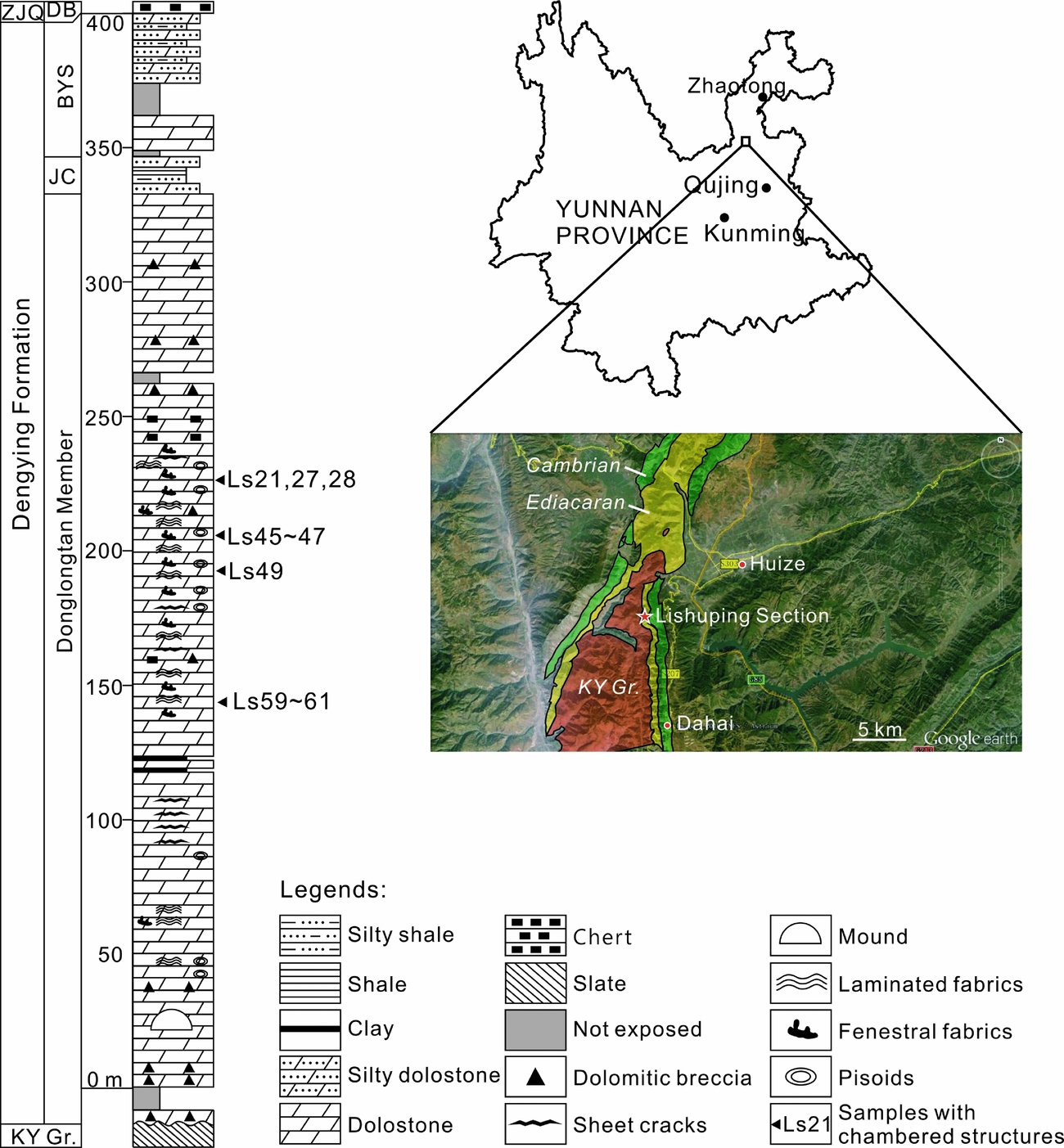
The studied materials were collected from an outcrop located ~10 km southwest of the centre of Huize County, adjacent to Lishuping Village, Yunnan Province, SW China (Fig. 1). In this region, Ediacaran deposits unconformably overlie the Kunyang Group, which was metamorphosed during the Jinning Movement at the Mesoproterozoic–Neoproterozoic transition. The hiatus corresponds to a period when the Huize region was a NNW–SSE-stretching hill and then an island, and not subject to deposition (Yunnan Bureau of Geology and Mineral Resources, 1995). In the investigated outcrop, the upper Ediacaran Dengying Formation directly overlies the Kunyang Group and conformably underlies the Daibu Member of the Zhujiaqing Formation (Fig. 1).
Location and stratigraphic log of the Lishuping Section. Abbreviations (in alphabetic order): BYS – Baiyanshao Member; DB – Daibu Member; JC – Jiucheng Member; ZJQ – Zhujiaqing Formation; KY Gr. – Kunyang Group.
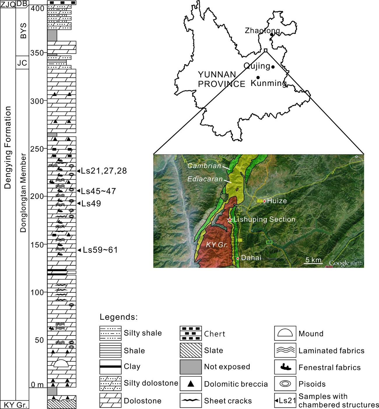
Exact chronological data are lacking for the investigated outcrop, but the age of the strata can be estimated through correlative rock units. A 551 Ma U–Pb zircon age, measured from the volcanic ash bed below the Dengying Formation in the Yangtze Gorges, is broadly adopted as the lower chronological constraint for the Dengying Formation (Condon et al. Reference Condon, Zhu, Bowring, Wang, Yang and Jin2005; Zhu, Zhang & Yang, Reference Zhu, Zhang and Yang2007). Meanwhile, the most recent biostratigraphic studies of acanthomorphic acritarchs and small shelly fossils confirmed that the Daibu Member represents the lowermost Cambrian (Ahn, Reference Ahn2014; Yang et al. Reference Yang, Steiner, Zhu, Li, Liu and Liu2016). Therefore, the age of the investigated Dengying Formation is estimated as 551–541 Ma.
The Dengying Formation is subdivided into three members, namely the Donglongtan, Jiucheng and Baiyanshao members in ascending order (Fig. 1). The Donglongtan Member is a sequence of peritidal dolostones enriched with microbial deposits. With a hiatus at the base, the exposed part of this member is more than 300 m thick. The ancient water depth and terrestrial input increased during the deposition of the Jiucheng Member, resulting in a sequence of interbedded grey calcareous siltstone, greenish-grey shale and purplish silty shale, ~15 m thick. The Baiyanshao Member, ~53 m thick, consists of thick-bedded microcrystalline dolostones in the lower part, while fine siliciclastic components increase again in the upper part of this member.
Chambered structures were found in the Donglongtan Member only. Seventy-two rock samples were collected from this member and processed into 120 7.5×5.0 cm thin-sections. Polished slabs and thin-sections were observed using a Nikon SMZ18 and a Nikon ECLIPSE LV100NPOL microscope at the Nanjing Institute of Geology and Palaeontology, Chinese Academy of Sciences. A subset of thin-sections was further studied using a CL8200 Mk5-2 cathodoluminescence (CL) microscope at the Chinese University of Geosciences (Wuhan).
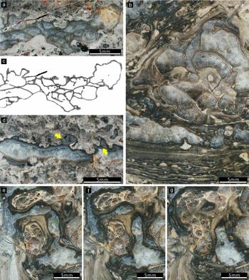
In order to investigate the three-dimensional (3-D) architecture of the chambered structures, a region of sample Ls45a was cut into a 3.6×3.4×0.5 cm slab and ground stepwise using a Hillquist thin-section machine. Fifty planes were taken from this slab with a distance of 21.5±3.4 μm between adjacent planes. The distances were controlled using a Mitutoyo micrometer. Each plane was manually polished using 3.5 μm silicon carbide, wetted and then scanned using an EPSON Scan L455 scanner with a resolution of 1200 dpi. The obtained images were initially aligned to each other using Adobe Photoshop CS3 Extended 10.0 and then built into a TIFF stack using ImageJ 1.49v. Using the software combination, the region of interest was cropped from the TIFF stack, and the contents of cement and host rock were removed from each plane, leaving only the chamber walls for 3-D reconstruction (Fig. 3a, c; ‘chamber walls’ cf. Section 3.b). Finally, the processed TIFF stack was adjusted to 8-bit greyscale mode and imported into Voreen 4.4 (http://voreen.uni-muenster.de) to visualize the 3-D architecture.
In addition to Ls45a, a part of sample Ls47 was also consecutively ground, polished and scanned. Because of the chamber system complexity and low contrast between the chamber walls and cement in this sample, these data were not further processed to create a 3-D model. However, this series of images also reveals the general growth habit of the chambers (Fig. 3e–g).
All studied samples and thin-sections are archived at the Nanjing Institute of Geology and Palaeontology, Chinese Academy of Sciences.
3. Results
3.a. Microfacies of the Donglongtan Member
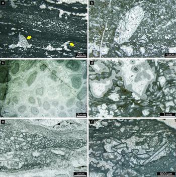
The exposed part of the Donglongtan Member exhibits evaporitic peritidal facies. Autochthonous microcrystalline dolomitic deposits with fenestral and laminated fabrics are dominant from the base of the measured outcrop, at 0 m, to ~230 m. Microbial bindstone, grainstone and packstone with sand-sized intraclasts occur sporadically as layers or lenses (e.g. Fig. 2a), reflecting the temporary influence of agitated water. Pisoids showing inversely graded bedding, an irregular shape and bridged coats are also common (Fig. 2c). Euhedral pseudomorphs of gypsum were observed at several levels as indicators of an evaporitic environment (Fig. 2a). In addition, some keg-barrel-shaped pseudomorphs were probably left by anhydrite crystals (Fig. 2b, cf. Warren, Reference Warren2006, p. 39).
Sedimentary structures in the Donglongtan Member. (a) Lenticular deposits of peloidal grainstone intercalated in fenestral fabric. Two gypsum pseudomorphs are indicated with arrows. (b) A keg-barrel-like pseudomorph, probably left by an anhydrite crystal. (c) Pisoids. (d–f) Structures composed of elements which contain thin, dark micritic envelopes surrounding bright sparitic centres. Among them, (e) and (f) are obvious allochthonous deposits of cortoids bound by microbial laminae, while (d) is likely autochthonous microbial deposits. All photos are oriented upwards. Sample numbers: (a) Ls36; (b) Ls23; (c) Ls35c; (d) Ls22; (e) Ls03; (f) Ls14.

The upper part of the exposed Donglongtan Member, from ~230 m to ~330 m of the measured outcrop, is dominated by microbial bindstone with silt- to sand-sized intraclasts. Many clasts exhibit a dark microcrystalline envelope and bright sparitic centre (Fig. 2e, f). Similar clasts were once interpreted as remnants of the calcimicrobe Renalcis (e.g. Zhu & Luo, Reference Zhu and Luo1992). However, compared with Renalcis (cf. Pratt, Reference Pratt1984; Riding & Voronov, Reference Riding, Voronov, Toomey and Nitecki1985; Riding, Reference Riding and Riding1991), these clasts have much thinner microcrystalline ‘walls’ and more irregular shapes. Some are elongated or even rectangular in thin-section, indicating that they are rather cortoids than calcimicrobes. Nonetheless, the elements with microcrystalline rims and sparitic centres at the level of 228 m may have a different origin from the intraclasts; the elongated or even filamentous forms can occur together with rounded forms within a 1×1 mm area, and the former can be contorted around or truncated by some early lithified cavities (Fig. 2d). Re-deposition of indurated clasts rarely results in such a state of organization.
3.b. Description of the Dengying chambered structures
Chambered structures were found at several levels where fenestral and laminated fabrics are developed (Fig. 1). Based on morphological features and the host rock fabric, these structures are here classified into two types, DYC-1 (Denying chambered structure type-1) and DYC-2 (Denying chambered structure type-2), and described separately.
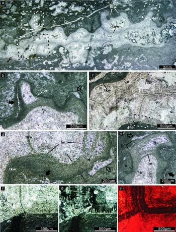
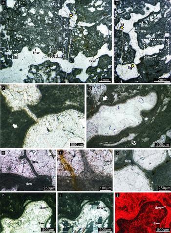
DYC-1 developed within microcrystalline dolostone with fenestral fabrics. In hand specimen, it appears as millimetric to centimetric, spar-cemented sheet cracks or large fenestral cavities (Fig. 3a, c, d). While observed under the microscope, they are generally composed of a thick wall, which separates the cavity from the host rock, and thin walls, which divide the cavity into polygonal subordinate spaces (Figs 4a, 5a, b). However, in some places, the thick wall is absent and the cavity boundary merely defined by a thin wall (e.g. Fig. 4c, indicated with the solid arrow in Fig. 5d). Here we temporarily and intuitively adopt the word ‘wall’ to describe these structures because they separate spaces when observed in thin-section, consecutively ground planes and 3-D images (details in the description that follows). The true nature of these structures will be further discussed in Sections 4.b and 4.c.
Chambered structures in polished slabs. (a, c, d) Dengying chambered structure type-1 (DYC-1), sample Ls45a. (a) The first plane of the consecutively ground DYC-1 sample Ls45a. (c) The processed image of the first plane, in which cement and host fabrics were removed, only the chamber walls remaining. The image was adjusted to an 8-bit greyscale mode before importing into Voreen. (d) A chambered structure whose thin walls are not well developed, but are visible in the arrowed places. A thin-section photo of this kind of chamber is shown in Figure 7a. (b, e–g) Dengying chambered structure type-2 (DYC-2), sample Ls47. (e–g) Part of the consecutively ground planes of sample Ls47, showing the spar-cemented growth cavity between two bulbous chambers. All photos are oriented upwards.

(a) Overview of a sheet-crack-like DYC-1 sample in thin-section, oriented upwards. The areas in dashed rectangles are enlarged in (b–e) with rotation of different angles. (b) The grumelous fabric of the host rock, thick wall and gaps between them. The two types of gaps are indicated with solid and hollow arrows (see Section 3.b in the main text for details). (c) Showing where the thick wall is present at the chamber ceiling and absent at the bottom. The area in the rectangle is enlarged in (f–h). (d) Showing part of the thick wall where the laminated inner structure is vague but discernible. A thin wall is connected to the inner rim of the thick wall with a cuspate structure. The two types of gaps between the thick wall and host rock are indicated with solid and hollow arrows, respectively. (e) Enlarged view of the small protrusions on the upper surface of the chambered structures. (f–h) Enlarged view of the area in the rectangle in (c) under plane-polarized light (f), crossed polarized light (g) and CL (h). The thin wall in this part is in direct contact with the grumelous fabric in the host rock, and is overgrown by bladed, isopachous cement that exhibits dull CL. Abbreviations (in alphabetic order): ir – inner rim; lm – laminated structure; or – outer rim; pr – protrusion; tkw – thick wall; tnw – thin wall. Sample number: Ls45a.

(a, b) Overview of fenestrae-filling DYC-1 in thin-section. Arrows and dashed rectangles indicate places which are enlarged in (c–j). (c) The innermost lamina of the thick wall overgrows a fissure in earlier laminae. The arrow indicates where a lamina in the thick wall is separated from other laminae. (d) A part of (b), exhibits well-preserved lamination in the thick wall. A gap between the thick wall and host rock is indicated with a hollow arrow. The solid arrow indicates where a lamina diverges from the thick wall and directly contacts the host rock. (e) The innermost lamina of the thick wall diverges from other laminae to form a thin wall. (f) A thin wall is connected to the innermost laminae of the thick wall with a cuspate tubercle. (g) The innermost lamina of the thick wall overgrows the tubercles formed by earlier laminae. (h–j) The same area under plane-polarized light (h), crossed polarized light (i) and CL (j), where the chamber wall is immediately overgrown with a thin, isopachous cement, which exhibits dull CL. Abbreviations: is – isopachous cements; for others see the caption of Figure 4. All photos are oriented upwards. Sample number: Ls45b.

The thick walls exhibit variable thicknesses up to hundreds of micrometres and a laminated inner structure in well-preserved samples (e.g. Fig. 5d, e). In other samples, the lamination can be vague (e.g. Fig. 4d) or even indiscernible (e.g. Fig. 4b). The outer rim of the thick wall, which is in direct contact with the host rock, shows an irregular outline (e.g. Fig. 4a, b, d, e). In contrast, the inner rim deviates from the shape of the outer rim and tends to form a rather smooth curve (e.g. Figs 4a, b, d, e, 5a–d). In some samples, the innermost lamina of the thick wall overgrows the deformation of earlier laminae (Fig. 5c, g). At the contact with the thick walls, the host rock often exhibits a grumelous texture (Figs 4b, 5c, d).
Gaps cemented by microspars are sometimes present between the thick wall and host rock. In some, the gap margin is irregular and defined by the shape of neomorphic crystals (indicated with solid arrows in Fig. 4b, d, e), indicating that these structures were probably formed owing to neomorphism or overprinted by this process. This phenomenon is also observable in some thin walls (Fig. 8g). In the others, the gap margin is smooth (indicated with hollow arrows in Figs 4b, d, e, 5d), indicating that the cement crystals grew in pre-existing spaces. These spaces were likely formed during the growth or decay of the chambered structures.
Different from the thick walls, most thin walls retain a homogeneous inner structure and uniform thickness (Figs 4, 5). However, this thickness is variable among different specimens, from 20 μm to 100 μm. Thin walls are perpendicularly or obliquely connected to the thick wall with direct contact or cuspate tubercles (Figs 4c, d, 5f). Sometimes, the innermost lamina of the thick wall diverges from other laminae to form a thin wall (Fig. 5e).
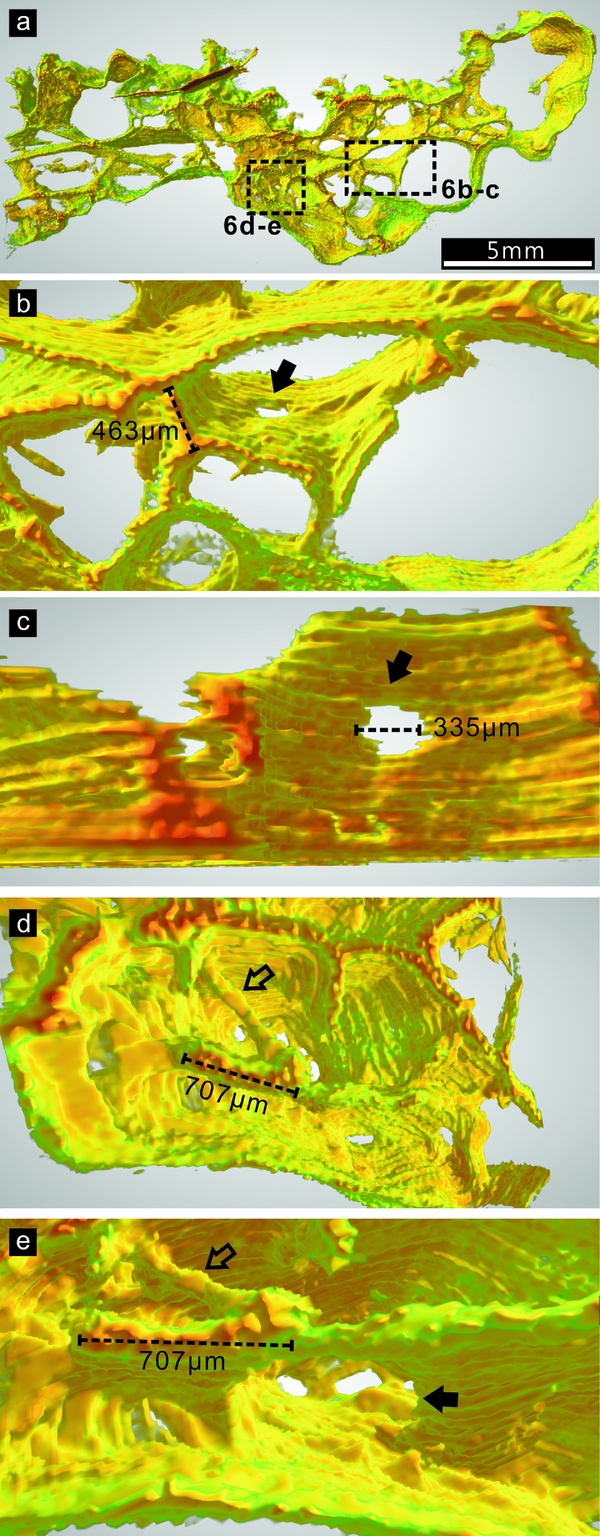
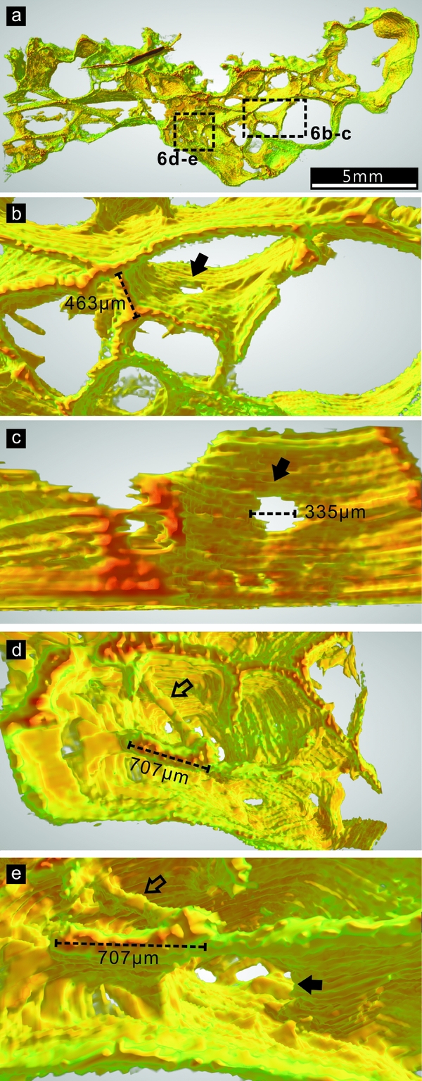
According to the 3-D reconstruction of Ls45a, the thin walls are primarily smooth, uniform and continuous surfaces (Fig. 6 and Figs S1, S2 in the online Supplementary Material available at http://journals.cambridge.org/geo). Some of these surfaces bear sub-circular holes (Fig. 6b–c, e), and are connected to short filamentous elements (Fig. 6d, e). The longitudinal cross-section of a filament may be indistinguishable from that of a surface when viewed in polished slabs.
Three-dimensional (3-D) architecture of part of the DYC-1 sample Ls45a. A ground plane of this sample is shown in Figure 3a. The colours in the 3-D image correspond to the darkness of the original material in 8-bit greyscale mode: red and green represent the darkest and lightest parts, respectively; orange and yellow represent the moderate darkness between the two ends. (a) Overview of the 3-D model. The areas in rectangles are enlarged in (b–e). (b) A hole in the continuous surface of the thin wall, indicated with a solid arrow. (c) A closer view of the hole in (b). The thin walls above are clipped to better illustrate the hole. (d) A filament (hollow arrow) is connected with thin walls. (e) A rotated view of the structures in (d). The solid arrow indicates a hole in the surface.
Both thick and thin walls are now composed of microcrystalline dolomite, which emits red CL similar to the microcrystalline dolomite in the host rock (Figs 4f–h, 5h–j). These walls are immediately overgrown by bladed, isopachous cement, which exhibits dull CL. The remaining chamber spaces are filled with blocky dolomite spars.
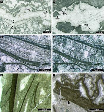
In some DYC-1 samples, thin walls do not appear to be well developed or preserved compared with the archetype described above (Figs 3d, 7a, b). In one sample, multi-laminated structures resembling thick walls, without growth along the cavity wall, appear to have disassembled into several thin-wall-like laminae (Figs 7a, c, d). In another example, structures appearing like partially destroyed and strongly crinkled thin walls are preserved (Fig. 7b).
(a, b) DYC-1 samples in which thin walls are not well developed. The area in the dashed rectangle in (a) is enlarged in (c, d). The intensive contortion of the walls in the upper part of (b) possibly represents the ductile deformation of partially destroyed thin walls. A polished slab of this kind of DYC-1 is shown in Figure 3d. (c, d) Disintegration and contortion of the thick-wall-like multi-laminated structure, in plane and crossed polarized light, respectively. (e, f) Fragmented chamber walls from the Cryogenian Rasthof Formation, Namibia. (e) A thin wall is connected with the thick wall with a cuspate tubercle. (f) An individual lamina diverges from the multi-laminated thick wall (arrow), and some other laminae exhibit the same intensive contortion as shown in (b). The Namibian samples are now archived at the University of Göttingen, Germany. Abbreviations: see caption for Figure 4. Photos in (a–d) are oriented upwards. Sample numbers: (a–d), Ls45; (e, f) AAP 01 17.

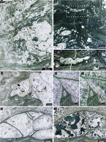
DYC-2 is characterized by millimetric to centimetric, bulbous or lenticular structures associated with laminated fabrics. These structures can encrust on (e.g. Figs 3b, e–g, 8a) or be intercalated in (e.g. Fig. 8b, c) microbial laminae. The subdivided chamber spaces are polygonal or lobate in form.
(a) Overview of a bulbous DYC-2 sample in thin-section. Areas in rectangles are enlarged in (d) and (g, h). The arrows in (a) and (d) indicate where a single lamina diverges from other laminae to form a thin wall. (b) Overview of lenticular DYC-2 in thin-section. The area in the dashed rectangle is enlarged in (c). The arrow indicates the chamber whose base conforms to the shape of the underlying laminae, while the upper part truncates the laminae at the same level. (c) Enlarged view of (b), illustrating the abruptly truncated laminae above the chambered structure. (d) An enlarged view of a part of (a), showing that contorted laminae merge to form thin walls. The area in the dashed rectangle is enlarged in (e, f). (e, f) Part of (d) observed in plane and crossed polarized light, respectively, showing that the walls are immediately overgrown by isopachous, bladed cements. (g, h) Part of (a) observed in plane and crossed polarized light, respectively. The chambers are surrounded by dark, continuous laminae, which are connected with the thin walls with direct contact and cuspate tubercles. The chamber walls are immediately overgrown by a thin layer of isopachous, bladed cements. The photos in (a) and (b) are oriented upwards. Sample numbers: (a), (d–h), Ls47; (b, c), Ls61.

DYC-2 does not have a prominent thick wall like DYC-1. However, the laminae immediately surrounding the chambers are darker and more continuous than the others in the laminated fabrics (Fig. 8a, d, g, h).
The thin walls of DYC-2 are homogeneous in inner structure, but are not always regular in thickness (Figs 3b, c, 8a); although most maintain a thickness of 40–60 μm, a thickness of several hundreds of micrometres is found in a few places. Similar to that of DYC-1, the thin walls of DYC-2 can be connected to the surrounding dark laminae with direct contact or cuspate tubercles (Fig. 8c), or formed by a lamina diverging from others (arrows in Fig. 8a, d). In addition, some bundles of laminae converge to form a thin wall in DYC-2 (Fig. 8d–f). The consecutively ground planes of sample Ls47 demonstrate that most walls observed in 2-D cross-sections are continuous surfaces in 3-D space (Fig. 3e–g).
The walls of DYC-2 are also immediately overgrown by bladed, isopachous cement, and the remaining chamber spaces are filled with blocky cement (Fig. 8e–h).
4. Discussion
4.a. Comparison with Cryogenian chambered structures
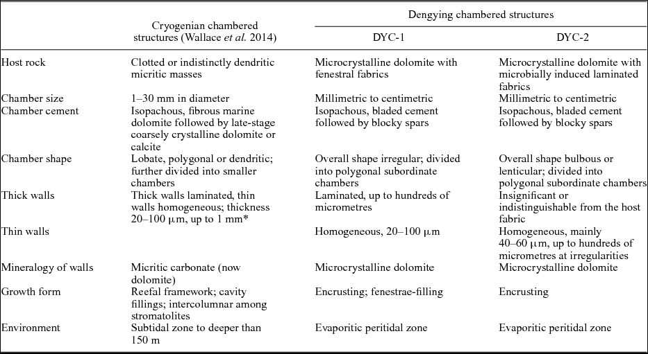
The Cryogenian chambered structures found in Australia and Namibia ‘consist of multiple macroscopic and microscopic cavities. . .with walls consisting of micritic carbonate’ (Wallace et al. Reference Wallace, Hood, Woon, Hoffmann and Reed2014, p113); the walls are either thin and homogeneous, or thick and laminated. The DYC-1 and -2 described above are both consistent with these structures in basic construction: (1) all the Ediacaran and Cryogenian chambered structures are embedded in microbially induced fabrics; (2) they have multi-laminated thick walls and homogeneous thin walls; and (3) their chamber sizes, wall thicknesses and cement generations are comparable. A detailed comparison between the Cryogenian and Dengying structures is presented in Table 1, in which all the described characteristics of the former are summarized.
Comparison between Dengying and Cryogenian chambered structures
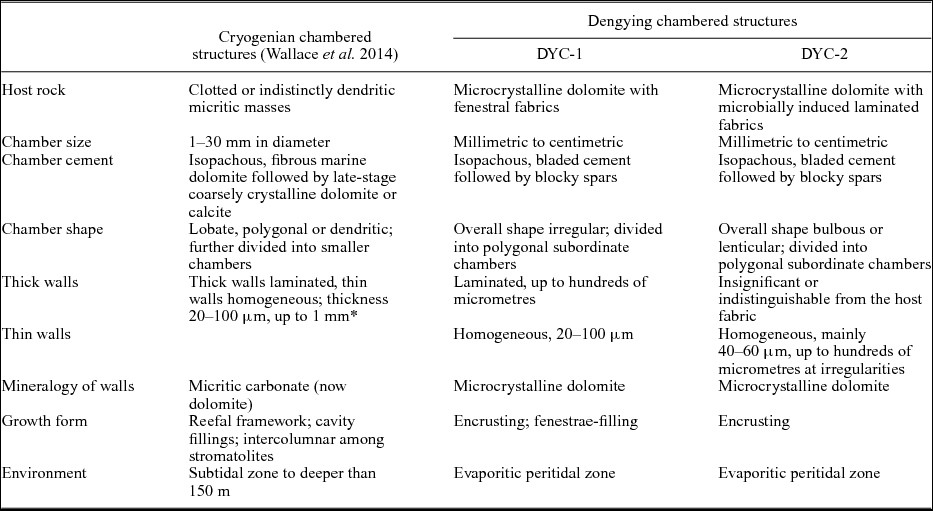
* The thicknesses of thick and thin walls were not described separately in Wallace et al. (Reference Wallace, Hood, Woon, Hoffmann and Reed2014).
In spite of the similarity in basic construction, the Dengying structures still show variations from the Cryogenian analogues in a few aspects.
First, except for a few DYC-2 specimens, the overall shapes of the Ediacaran chambered structures cannot be assigned to the three morphological categories of Cryogenian chambered structures, namely, (1) lobate structures, which are encrusting bulbous chambers sometimes containing subdivided polygonal secondary chambers; (2) dendritic structures, which are elongated and branching chambers sporadically showing convex thin walls; and (3) polygonal structures, which are characterized by polygonal chambers, without any primary–secondary hierarchy or subdivision. The overall shapes of DYC-1 are either sheet-crack-like or irregular, while DYC-2 structures are either bulbous or lenticular. Nearly all the DYC-1 and -2 structures have subdivided chambers, i.e. their chamber walls are hierarchical.
Second, some lobate and dendritic forms of the Cryogenian structures are unequivocally frame builders (Wallace et al. Reference Wallace, Hood, Woon, Hoffmann and Reed2014, Reference Wallace, Hood, Woon, Giddings and Fromhold2015), while none of the Dengying structures appear to be frame building.
In addition, the Cryogenian structures from South Australia were estimated to have developed in a palaeo-water-depth of greater than 150 m (Wallace et al. Reference Wallace, Hood, Woon, Giddings and Fromhold2015). The microbial member of the Rasthof Formation, where the Namibian chambered structures occur, exhibits subtidal facies (Le Ber et al. Reference Le Ber, Le Heron, Winterleitner, Bosence, Vining and Kamona2013). In comparison, the Dengying structures developed in a much shallower, peritidal environment.
4.b. Growth of the Dengying chambered structures
For both the Cryogenian and Dengying chambered structures, the features of the chamber walls are critical in deciphering their provenance. However, in the previous study of the Cryogenian chambered structures, this issue was not addressed in detail. Here, the close observation of the Dengying material allows a more comprehensive discussion.
The multi-laminated thick walls in DYC-1 samples may be disassembled into several individual laminae, which are similar to the homogeneous thin walls (e.g. Figs 5c, 7c–d). The DYC-2 samples lack prominent thick walls, but the host fabric per se is composed of thin microbial laminae. In both DYC-1 and -2, a thin wall can be formed by the innermost lamina of the surrounding multi-laminated system (i.e. the thick walls or the laminated host fabrics), which diverges from other laminae. In DYC-2, thin walls can additionally be formed by the convergence of multiple laminae. These phenomena indicate that the thick and thin walls, as well as the laminated fabric in DYC-2, have the same origin, and the continuous, uniform laminae are the basic building blocks of the chamber walls. In some cases, the thin walls appear to be strongly crinkled (Figs 7b), indicating that they possibly had a ductile stage before lithification. It is noteworthy that similar wall features have also been observed in some fragments of the Cryogenian chambered structures from Namibia (Fig. 7e, f).
In some DYC-1 samples (e.g. Ls45b), thick walls show a mode of inward accretion, where the innermost lamina overgrows the deformation of earlier laminae (Fig. 5c, g). This indicates that these DYC-1 structures occupied pre-existing fenestral cavities. Accordantly, these structures do not show any preferential growth orientation (Fig. 5a, b), and some gaps between the thick wall and cavity wall may have formed owing to the overgrowth of the former (e.g. Fig. 5b, d). However, for the other chambered structures, there are no definitive indicators for the accreting direction of the laminae in the thick wall.
In contrast to the fenestrae-filling DYC-1, the sheet-crack-like DYC-1 (sample Ls45a) shows a preferred upward growth orientation. This is reflected by the upper surface of these structures bearing many small, bulbous protrusions, which are nearly absent from their lower surface (Figs 3a, 4a, 6 and S2 in the online Supplementary Material available at http://journals.cambridge.org/geo). There is no trace of geopetal fillings that would be responsible for the flatness of the base. The small protrusions on the upper surface may represent new chambers in an initial stage, extending into the free space above the older parts.
Also, it seems that the bulbous DYC-2 chambers grew in a free space. In the consecutively ground sample Ls47, an interspace between two bulbous chambers is filled by sparitic cement. The smooth margin of the chambers and completeness of their overgrowing laminae indicate that this space was probably formed by growth, instead of erosion (Fig. 3e–g). Similarly, the lenticular DYC-2 chambers intercalated in laminated fabrics appear to have developed contemporaneously or paracontemporaneously with the microbial mat: the lower surface of the chambers generally conforms with the shape of the underlying laminae while the upper part of the chambers truncates the overlying laminae (Fig. 8b, c).
4.c. Interpretation of the chambered structures
Wallace et al. (Reference Wallace, Hood, Woon, Hoffmann and Reed2014) distinguished the Cryogenian chambered structures from fenestral cavities, travertine gas bubbles and methane release structures based on their well-defined, smooth and regular walls. The Dengying chambered structures can be differentiated from these inorganic structures for the same reasons. If not associated with microbial deposits, fenestral cavities and gas bubbles hardly have components comparable with the chamber walls. The laminated thick walls exhibit gaps at the contact with the cavity wall, and their innermost laminae can diverge to form thin walls, which subdivide the chamber space. These features distinguish them from inorganic precipitates lining cavity walls. Thin chamber walls are different from lithified bubble walls or precipitates between comparted substances by containing sub-circular holes. In addition, a few ‘thin walls’ in thin-section may represent filaments in 3-D space. For these reasons, here the discussion focuses on the possible biogenic provenances of the chambered structures, which have been addressed in the previous study: (1) proto-sponges, (2) calcimicrobes and microproblematica, and (3) microbialites.
4.c.1. Comparison with sponges
A few structures in Cryogenian carbonates have been suggested as body fossils of sponge-grade organisms, including Otavia from Namibia (Brain et al. Reference Brain, Prave, Hoffmann, Fallick, Botha, Herd, Sturrock, Young, Condon and Allison2012) and calcified irregular fragments from South Australia (Maloof et al. Reference Maloof, Rose, Beach, Samuelsson, Calmet, Erwin, Poirier, Yao and Simons2010). These materials are asymmetrical bodies containing cavities which are reminiscent of the aquiferous system of poriferans. However, other provenances, e.g. microbial deposits, protozoan fossils or depositional clasts, were not excluded for these structures (Antcliffe, Callow & Brasier, Reference Antcliffe, Callow and Brasier2014). Chambered structures are apparently different from these structures in morphology.
The polymud fabric, which was mainly known from the Phanerozoic and related to degradative calcification of metazoan extracellular collagenous matrix, contains secondary voids associated with multiple generations of authigenic carbonate mud. This fabric has been reported from the Cryogenian Little Dal Group (Neuweiler, Turner & Burdige, Reference Neuweiler, Turner and Burdige2009). However, the secondary voids in the polymud fabric are different from the chambers described here, in lacking smooth walls and often exhibiting geopetal fillings and scalloped margins.
Owing to their general shape, the Cryogenian lobate chambered structures were compared with the basal skeleton of some hypercalcified sponges, especially that of aporate sphinctozoans and labechiid stromatoporoids, although it was determined that the chambered structures are different from these sponge skeletons because of lacking pores and pillars (Wallace et al. Reference Wallace, Hood, Woon, Hoffmann and Reed2014). A ‘proto-sponge’ affinity was proposed to interpret these disparities, and the lack of pores in the chamber walls was assumed to reflect osmotrophic feeding of primitive organisms. However, the organization and skeletalization of the hypothesized proto-sponges was not discussed.
The fossil skeletons of hypercalcified sponges were not confirmed as having poriferan affinity before the discovery of similar skeletons in modern Jamaican sponges (Hartman, Reference Hartman1969; Hartman & Goreau, Reference Hartman, Goreau and Fry1970). Years of studies revealed that the known hypercalcified sponges secrete their basal skeletons either inside the soft tissue (e.g. Vaceletia) or outside the basopinacoderm (e.g. labechiid stromatoporoids), or intracellularly secrete calcitic spherulites and cement them exosomatically (e.g. Astrosclera) (Stearn, Reference Stearn1975, Reference Stearn2010; Wood, Reference Wood, Reitner and Keupp1991; Reitner et al. Reference Reitner, Wörheide, Lange and Schumann-Kindel2001).
If the hypothesized proto-sponges adopted the first strategy, then chamber walls necessarily have pores, because pores serve not only as inhalant and exhalant openings, but also as paths through which the soft tissue is connected and could migrate (cf. Müller-Wille & Reitner, Reference Müller-Wille and Reitner1993; Vacelet, Reference Vacelet, Hooper, Soest and Willenz2002). Although sub-circular holes are observed in some chamber walls, it is difficult to confirm whether they represent organism growth or wall decay or mechanical destruction. If the proto-sponges secreted the skeletons outside the basopinacoderm while the soft tissue migrated, similar to labechiid stromatoporoids secreting their cysts, the derived skeletons would not have needed pores. However, cysts are single-layered and do not form multi-laminated structures (cf. Stearn et al. Reference Stearn, Webby, Nestor and Stock1999). Finally, the chambered structures do not show any spherulite-like components corresponding to the third mode of skeleton construction.
In summary, the current understanding of sponge skeletogenesis does not support the scenario that a sponge-like organism could build skeletons like the chambered structures.
4.c.2 Comparison with calcimicrobes and microproblematica
Calcimicrobes and microproblematica are often composed of small elements, which are tens to hundreds of micrometres in size and show certain regular shapes, such as tubular, circular or botryoidal cells (e.g. Riding, Reference Riding and Riding1991; Flügel, Reference Flügel2010). The investigated chambered structures are generally distinguishable from these fossils in exhibiting much larger (mostly millimetric to centimetric) and less regular subordinate chambers.
In spite of the size disparity, the lobate chambered structures may be reminiscent of the Palaeozoic microproblematicum Wetheredella Wood, Reference Wood1948 in thin-section. However, Wetheredella is composed of non-septate, sub-circular tubes, while the Precambrian chambered structures do not have such a regular shape, and their lobate chambers can be further divided into polygonal subspaces.
The Mesozoic microproblematica Lithocodium and Bacinella resemble the chambered structures in containing spar-cemented cavities which are sometimes segmented by regular, thin micritic walls. However, these cavities are surrounded by thick, homogeneous micritic material and lack multi-laminated structures like the thick walls. In addition, the cavity system of many Lithocodium and Bacinella species is more elegantly organized than that of the chambered structures. For instance, in both type species L. aggregatum and B. irregularis, the cavity system consists of a prostrate and an erect part, and the latter is in the form of ramified filamentous tubes with reducing diameters (Schlagintweit, Bover-Arnal & Salas, Reference Schlagintweit, Bover-Arnal and Salas2010; Schlagintweit & Bover-Arnal, Reference Schlagintweit and Bover-Arnal2013). Because of their morphological complexity, these fossils were recently reinterpreted as algae or sponge bores (Schlagintweit, Bover-Arnal & Salas, Reference Schlagintweit, Bover-Arnal and Salas2010; Cherchi & Schroeder, Reference Cherchi and Schroeder2012; Schlagintweit & Bover-Arnal, Reference Schlagintweit and Bover-Arnal2013).
In addition, the Cretaceous ‘bacinellid textures’ and ‘lithocodoid-bacinelloid fabrics’, which have been removed from Bacinella and Lithocodium sensu stricto and compared to calcified microbial mats, also exhibit chamber-like patterns confined by regular micritic walls in 2-D cross-sections (Neuweiler & Reitner, Reference Neuweiler and Reitner1992; Schlagintweit, Bover-Arnal & Salas, Reference Schlagintweit, Bover-Arnal and Salas2010; Schlagintweit & Bover-Arnal, Reference Schlagintweit and Bover-Arnal2013). However, the 3-D architecture of these structures has not been studied. It is unknown whether their micritic walls are truly comparable with the thin walls of the Neoproterozoic chambered structures.
4.c.3. Comparison with microbialites
In fact, the laminae-based construction and growth pattern of the chambered structures readily indicate a microbialite interpretation. Especially in the DYC-2 samples shown in Figure 8, the thin walls are closely associated with microbial laminae in the surrounding fabrics. It is also conceivable that the biofilm-forming microbial consortia could have inhabited pre-existing fenestral cavities. They may have initially accreted on the cavity wall, then started to occupy the central space by developing angularly extending, single-laminated films (i.e. thin walls), and finally formed the fenestrae-filling DYC-1. The filamentous elements may represent the initiation of a thin wall, and the sub-circular holes in some thin walls possibly have resulted from biofilm decay. For chambered structures showing encrusting habits, the chamber space may have been produced by gas trapped in biofilms.
The real difficulty with the microbialite interpretation is finding an analogous laminae-based, chambered construction in known fossil or extent microbialites.
Many microbialites show chamber-like voids in thin-sections and polished slabs, but they are easily distinguishable from the Cryogenian and Dengying chambered structures because the void walls are irregular, without consistent thicknesses and smooth rims (e.g. Knoll, Wörndle & Kah, Reference Knoll, Wörndle and Kah2013; Wilmeth et al. Reference Wilmeth, Corsetti, Bisenic, Dornbos, Oji and Gonchigdorj2015). The Archaean fenestrate microbialites consist of thin (1–10 μm), biofilm-like laminae that drape from thicker (100–300 μm) vertically oriented surfaces called ‘supports’. Chamber-like voids are enclosed by the filmy laminae and supports (Sumner, Reference Sumner1997, Reference Sumner, Riding and Awramik2000). The filmy laminae are similar to the thin walls of chambered structures in appearance (e.g. figs 2, 3 in Sumner, Reference Sumner, Riding and Awramik2000). However, the Neoproterozoic chambered structures do not contain morphological elements corresponding to ‘supports’. Furthermore, a recent study of some fenestrate microbialites of the plumose and plumose-cuspate forms revealed that their 3-D architectures are more complex than previously supposed. Tubular structures and interconnecting linear structures were newly identified (Rivera & Sumner, Reference Rivera and Sumner2014). This further differentiates these Archaean microbialites from the chambered structures, because the latter are primarily constructed from smooth, continuous laminae, containing only a few filamentous elements and lacking tubular structures.
In modern photosynthetic microbial mats, accumulated oxygen produces cavities of different shapes, including bubbles, tubes and irregular blisters. Recent studies of cultured, cone-forming cyanobacteria mats showed that surrounding these cavities, a dark, dense lamina associated with early precipitation of micritic high-Mg calcite can be formed (Bosak et al. Reference Bosak, Liang, Sim and Petroff2009, Reference Bosak, Bush, Flynn, Liang, Ono, Petroff and Sim2010). This lamina is similar to the thin walls in the chambered structures, with consistent thicknesses varying from 20 μm to 150 μm (figs S4–S6 in Bosak et al. Reference Bosak, Liang, Sim and Petroff2009; figs 5, 6 in Bosak et al. Reference Bosak, Bush, Flynn, Liang, Ono, Petroff and Sim2010). Moreover, this type of laminae appears to divide large voids, e.g. blisters, into irregular subordinate spaces (figs 2c, S5b in Bosak et al. Reference Bosak, Liang, Sim and Petroff2009). However, apart from fossilization potential, these laminae only appear as single layers and were not reported as stacking to form multi-laminated structures like the thick walls in the Neoproterozoic chambered structures. In addition, the fenestrae-filling DYC-1 fossils are unlikely to be related to photosynthesis.
In summary, although some microbially induced structures, e.g. the ‘bacinellid textures’ and ‘lithocodoid-bacinelloid fabrics’ and the rapidly calcified laminae associated with photosynthesis-induced bubbles, share some common features with the Neoproterozoic chambered structures, there are still discrepancies. Further investigations and discoveries are required to ultimately decipher the biofilm-forming microbial consortia and associated environmental factors that produced the Neoproterozoic chambered structures.
5. Conclusions
The chambered structures from the Ediacaran Dengying Formation are comparable to the previously described Cryogenian chambered structures in basic construction. Their discovery in the Ediacaran indicates that chambered structures probably occurred more broadly in the fossil record than previously realized but were overlooked. As an example, the ‘cellular crusts’ from the Neoproterozoic Little Dal Group are also similar to the chambered structures according to the published description and illustration (Turner, Narbonne & James, Reference Turner, Narbonne and James1993), but did not receive further investigation. Nonetheless, taking the ‘cellular crusts’ into account, the known records of chambered structures are still sparse and restricted to the Neoproterozoic.
The newly observed morphological details of the Dengying and some Cryogenian chambered structures indicate that the basic building blocks of the chamber walls are thin, homogeneous laminae, which primarily correspond to continuous surfaces in 3-D space. The morphology and growth pattern of these laminae distinguish the chambered structures from sponge skeletons and indicate a probable microbial origin. However, similar laminae-based, chambered constructions are yet unknown in fossil and extant microbialites.
New, relevant discoveries in the future are required to answer two overarching questions: (1) Do the chambered structures occur in other geological time periods? (2) What were the exact microbial consortia and/or environmental factors that produced these structures and made them construct reef frames in the Cryogenian?
Acknowledgements
We appreciate the suggestions from Prof. Junming Zhang (NIGPAS) for field trip preparation, and help from Dr Fangchen Zhao (NIGPAS) and Mr Zhaonian Wu (NIGPAS) with fieldwork. The comments from the two anonymous referees were valuable in improving the quality of the manuscript. This study was supported by the CAS Key Laboratory of Economic Stratigraphy and Palaeogeography, Nanjing Institute of Geology and Palaeontology and the Strategic Priority Research Program (B) of the Chinese Academy of Sciences (XDB18030304).
Supplementary material
To view supplementary material for this article, please visit https://doi.org/10.1017/S001675681700053X.