1. Introduction
Real-time autonomous navigation in a dynamic environment has become a major thrust area of research and large-scale development in many fields like agriculture, space exploration, battlefield, warehouses, factories, rescue operations, and academia. In a static environment, the planner finds the solution to the robot motion planning before execution. In a static 2D or 3D environment, numerous path planning algorithms are available such as grid-based (Dijkstra algorithm, A*, D*), cell decomposition, roadmap-based (probabilistic roadmaps, visibility graphs, Voronoi diagrams), virtual force field-based (artificial potential field, gravitational force field, electrostatic potential field), sampling-based (RRT), fuzzy logic, neural network-based, etc. However, the path planner/replanner updates the obstructed portion of the robot’s path while moving on the same path toward the goal in a dynamically changing environment. Hence, replanning methods require modifications to reduce computational load and react synchronously with environmental change. Most of the researches on dynamic motion planning face the issues of replanning execution time and computational complexity.
In the middle of the 20th century, motion planning algorithms were focused on finding an obstacle-free path between the start and the goal in a known environment, that is, the “piano movers” problem [Reference Latombe1]. NP-hardness (nondeterministic polynomial-time hardness) defines the property of a class of problems that are informally “at least as hard as the hardest problems in NP.” A complete planner (one that finds a path whenever one exists and reports that no one exists otherwise) cannot find the robot’s path as a point in the plane, with bounded velocity and arbitrary moving obstacles, which makes such problems NP-hard [Reference Canny2]. Recently, most motion planning algorithms are dependent on sensory feedback about the changing environment and obstacles. The planning algorithm cannot generalize the configuration space over time during real-time planning in an unknown environment. Extensive studies have been found in the literature on 2D motion planning to handle dynamic environmental changes and moving obstacles [Reference Canny2–Reference Fox, Burgard and Thrun7] during the last decade of the 20th century. Most dynamic motion planning approaches are based on velocity, state time space, artificial potential fields, artificial intelligence, associability graph, and probability. A few works also introduced the factor of uncertainty in the motion of obstacles [Reference Inoue, Inoue and Okawa6]. Over the past few decades, researchers thrive on more efficient alternatives for dynamic path planning problems.
Some algorithms have been modified to deal with moving target location in dynamic environments, that is, inevitable collision states [Reference Fraichard and Asama8], partial motion planning [Reference Petti and Fraichard9], dynamic window approach [Reference Shiller, Large and Sekhavat10], and probabilistic time space [Reference van den Berg11]. In the past decades, bioinspired optimization algorithms have emerged as new and improved alternatives for robot path planning in unknown environments, such as the ant colony algorithm [Reference Kai-bo, Hai-yan, Yang and Shi-juan12], particle swarm algorithm [Reference Nasrollahy and Javadi13], neural network algorithm [Reference Hwu, Wang, Oros and Krichmar14], and improved genetic algorithm [Reference Zhang, Zhao, Deng and Guo15]. However, such bioinspired approaches have some shortcomings, making them unsuitable for 3D dynamic path planning for redundant robots, that is, local minima, slow convergence rates, and absence of population cooperation.
Current studies on dynamic motion planning deal with many aspects, that is, goal perception, environment mapping, real-time path planning, dynamic obstacle avoidance, and motion control. Early asymptotically optimal roadmap algorithms construct a detailed connectivity graph over the configuration-space a priori and require conventional graph search techniques (e.g., A* or Dijkstra) to find a solution from the current position to goal states during the online planning phase. Such roadmap algorithms were ill-suited to incorporate dynamic changes due to a fixed obstacle layout requirement during the connectivity-related precomputation. Resolution optimal discrete graph replanning algorithms like D*-Lite [Reference Koenig, Likhachev and Furcy16] and Lifelong-A* [Reference Koenig, Likhachev and Furcy17] require an embedded grid to plan/replan traditionally within the workspace. These algorithms repair the graph connectivity by changing the weights of the edges using the equivalence of “no edge exits” or “infinite cost edge.” However, these algorithms are unable to incorporate the kinematics of robots. Later AD* [Reference Likhachev and Ferguson18] projected the robot’s state-space graph edges, which is kinodynamically feasible, into the workspace. However, the lattice graph with kinodynamic feasibility needs significant precomputation in the offline phase. One algorithm that outperforms the existing techniques in dynamic path planning and replanning is the RRT* method [Reference Karaman and Frazzoli19], which shows significant improvement from its predecessor, the basic Rapidly exploring Random Tree (RRT) method [Reference LaValle and Kuffner20] in terms of asymptotic convergence and path quality. It can explore various kinds of configuration space without being stuck in local minima. The major difference between RRT* and the aforementioned methods is that they depend on significant offline planning to create connectivity search graphs or the roadmap a priori. In contrast, single-query algorithms like RRT* and others are designed for frequent dynamic changes. RRT* has been widely used as a dynamic planner in the last decade by taking advantage of its inherent local rewiring feature within existing tree nodes. RRT* rewiring eliminates the requirement of entire search tree destruction and starts over. In the last decade, many modifications to basic RRT are implemented to store search tree waypoints and regrow it locally, that is, ERRT [Reference Bruce, Veloso, Kaminka, Lima and Rojas21], DRRT [Reference Qureshi, Iqbal, Qamar, Islam, Ayaz and Muhammad22], Multipartite RRT [Reference Zucker, Kuffner and Branicky23], RRT*-FND [Reference Adiyatov and Varol24]. DRRT starts the tree growth from the goal location to minimize the loss of branches. Unlike DRRT, Multipartite RRT preserves a subset of the search tree which can be pruned and reconnected from their previous states for dynamic regrowth. It is clubbing the features of DRRT and ERRT [Reference Bruce, Veloso, Kaminka, Lima and Rojas21]. LRF [Reference Gayle, Klingler and Xavier25] constructs additional search trees for multiple goals, retains disconnected branches like MP-RRT, and replans by merging the search trees or reconnecting branches. Unlike the above-mentioned RRT variants, RET [Reference Martin, Wright and Sheppard26] uses a bidirectional-RRT planner, where the forward tree root is updated with the moving robot’s current location, and additional sampling waypoints during replanning are calculated offline. The major difference between RRT* and the aforementioned single query algorithms is that RRT* is asymptotic optimality in the replanning phase. Another significant difference is that RRT* does not rely on the regrowth of new samples to reconnect the portions of the disconnected search tree by obstacles. In contrast, RRT* uses a rewiring feature to remodel the search tree around the obstacles using existing valid nodes. All of the algorithms mentioned above (except DRRT) plan from start to goal. It is necessary to replan from target to start location in order to make the existing search tree and root useful for all replans. Thus, prune/rewire/regrowth of the search tree node and its descendants can affect only a smaller portion of the tree. In practical experiments, robotic sensors detect changes near the tree leaves instead of the root.
Later, a replanning variant of RRT named Any-Time SPRT [Reference Otte27] uses random rewiring and node-insertion rewiring for asymptotic optimality, but it is computationally expensive than RRT*. RRT# [Reference Arslan and Tsiotras28] uses a more efficient rewiring cascade within local neighborhoods that carry cost-to-goal information in decreasing order through the search tree, but it is slower than RRT*. LBT-RRT [Reference Salzman, Shaharabani, Agarwal and Halperin29] maintains a “lower-bound” that returns asymptotically near-optimal solutions. LBT-RRT saves time by not updating some neighbors, but it is bounded by the runtime difference between RRT and RRT*, which means LBT-RRT cannot perform better than RRT*. Otte and Frazzoli [Reference Otte and Frazzoli30] describe the advantages of RRT* and use it to update the path during execution continuously in their variant of RRT* named as RRTx, which is used in the dynamic planning of holonomic robots.
Most dynamic motion planning approaches focus on 2D configuration space (C-Space), where obstacle space is easily separable from free space. However, a few algorithms are modified for 3D applications with two-wheeled robots [Reference Masehian and Katebi31], higher DOF robots [Reference Yoshida, Esteves, Belousov, Laumond, Sakaguchi and Yokoi32], and UAV [Reference Zhang and Duan33]. However, path planning of All-Terrain planetary Rover in a dynamically changing 3D even or uneven environment is totally different and computationally complex due to the wheel-terrain interactions [Reference Thomas and Vantsevich34]. Rekha et al. [Reference Raja, Dutta and Venkatesh35] presented a 10 DOF Rover’s path planning on static 3D rough/bumpy terrain. 10 DOF Rover contains six-wheel motors (6 DOF) and four steering motors (4 DOF) separately. The optimization required for wheel-terrain interaction while moving on uneven terrain is computationally too costly to be obtained in real time for a dynamic environment. Therefore, the CG-Space concept [Reference Katiyar and Dutta36] eliminates this optimization time during the path planning stage.
The main contribution of this study is the CG-Space-based RRT* algorithm for static path planning of 10 DOF Rover and dynamic rewiring within the existing search tree when a collision is detected with randomly moving obstacles. CG-Space is a locus of the Rover’s Center of Gravity in a discrete point cloud in a 3D global coordinate system while traversing on the given terrain. Once the RRT* space tree structure is generated over CG-Space, the invalid path portion can be rewired locally in real time without erasing the entire search tree. Since the path is planned/replanned over CG-Space, separate wheel-terrain optimization is not required during planning.
The paper is organized as follows: Section 2 describes 3D terrain mapping, Section 3 provides an overview of the Rover design, its corresponding CG-Space, dynamic obstacles, and moving target. Section 4 elaborates the dynamic replanning using RRT* over CG-Space. Section 5 contains the simulation details, comparison with another algorithm, and experimental setup. Section 6 ends with conclusions and future work.
2. Terrain mapping based on depth information
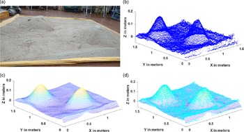
The terrain elevation data are provided to the planner using a Kinect V2 sensor, which is further utilized for determining wheel terrain contact. The Kinect V2 sensor collects the depth data by mapping the rock and sand type terrain profile into a 3D point cloud in its coordinate frame (C). The point cloud obtained in camera coordinates of Kinect is transformed as a spatial location in the world frame using a global transformation matrix
 $T_C^G$
. This transformation matrix is obtained using SVD (singular value decomposition)-based implementation in Point Cloud Library. After transformation, a 2D Gaussian filtering process converts the terrain data into a predefined mesh grid of 1.65 m in X direction and 1.6 m in Y direction with respect to the global frame (G) and avoids noisy terrain data at the border areas. A mesh grid form is created with 3 cm (as the wheel size is 8 cm, each grid was taken as 3 cm) in both X and Y directions. At any
 $i$
th point (
 ${x_i},{\rm{\;}}{y_i}$
) in the mesh grid, the corresponding elevation
 ${z_i}$
of the terrain is found by taking a weighted average of the elevations of all the points in the transformed and downsampled point cloud. Figure 1 shows an example of a particular sand terrain profile and a point cloud of the real terrain profile overlapped with the mesh grid form of terrain profile.
(a) Real terrain with two high gradient zones and (b) corresponding point cloud in the global frame, (c) mesh grid form of the terrain, and (d) meshed terrain overlapped with the point cloud.

3. Problem statement and assumptions
In this section, we discuss the Rover’s design, its CG-Space, and the path planning/replanning model briefly. Three components of the dynamic environment are important to the model: the robot, obstacles, and the target. The problem statement of this study is to replan the Rover path dynamically while traversing on uneven terrain.
3.1. Design and kinematics of Rover
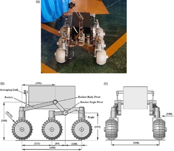
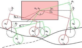
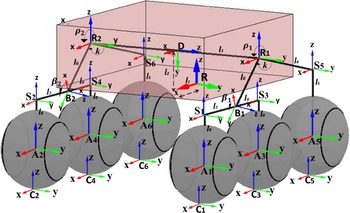
The Rover consists of six wheels, rocker, and bogie links, a differential, a central body, and a manipulator arm, as shown in Figure. 2. However, in this work, the arm is not considered. The Rover base joint-angle vector is denoted as
 $\;\hbar = \left[ {\rho \;{\beta _1}\;{\beta _2}\;{\psi _1}\;{\psi _2}\;{\psi _5}\;{\psi _6}} \right]$
, where
 $\rho $
,
 ${\beta _i}$
, and Ω
i
denote rocker angle, bogie angle, and the angular rotation of each steering wheel, respectively. Figure 3 shows the rocker-bogie mechanism with joint angles. Important local frames of the system with corresponding joint angles are shown in Figure 4. The constant parameters used in Rover are k=39 (angle for the rocker link), r = 0.075 (radius of wheel), l
1
= l
2
= 0, l
3
= 0.2, l
4
= 0.225, l
5
= 0.175, l
6
= 0.124, l
7
= 0.13, l
8
= l
9
= 0.095, The Rover can overcome maximum terrain gradient and sidewise slopes equal to 35°. Hence, the Rover maximum allowable threshold height, which it can climb, is 0.075 m. Quasi-static modeling of the Rover is sufficient as it moves with a very low velocity of 5 cm/s.
(a) Rover image and dimensions in (b) right side view and (c) front view.

Schematic diagram of rocker-bogie Rover with joint angles and steering angles.

Local coordinate frame of the important points at each side of the Rover.

3.2. CG-Space of the Rover
After the terrain mapping process is complete, the terrain elevation data (
 ${Z_{terrain}}$
) at each point
 $\left( {{X_i},{Y_i}} \right)$
of mesh grid are used to generate the CG-Space. A few assumptions are made to obtain the Rover pose over the CG-Space, that is, single-point contact between each wheel and the terrain; the terrain is nondeformable; wheels and the Rover links are rigid bodies. Each wheel contains a unique contact frame (
 ${C_i}$
) with the terrain, and its Z-coordinates in global frame are obtained using a homogeneous transformation between global frame (G) and
 ${C_i}$
. The detailed kinematics of the Rover is given in previous work [Reference Katiyar and Dutta36]. In order to keep a single contact point with the terrain, the difference between the terrain elevation and Z-coordinate of each wheel (
 ${Z_{terrain}} - {Z_i}$
) must be zero. Hence, the contact error between
 ${Z_i}$
and
 ${Z_{terrain}}\left( {X,Y} \right)$
given in Eq. 1 should be minimized.
 \begin{align}E\left( {H,\;\hbar ,\;{{\rm{\delta }}_i}} \right) = {Z_i}\left( {H,\;\hbar ,\;{{\rm{\delta }}_i}} \right) - {Z_{terrain}}{\rm{\;}}\left( {{X_i},{Y_i}} \right)\end{align}
Now, we have to optimize the values of the Rover parameters
 $\lambda = \left[ {\rho ,\;{\beta _1},{\beta _2},{\phi _x},\;{\phi _y},\;z} \right]\;$
which minimizes the contact error for a given position (X, Y,
 $\phi$
z
) on the terrain. The total of contact error of all wheels,
 $\epsilon$
, can be written as
 \begin{align} \in = {1 \over 2}{\rm{\;}}{E^T}\left( \lambda \right)E\left( \lambda \right)\end{align}
To solve the above nonlinear multivariable optimization problem, a single objective multivariable nonlinear constrained MATLAB optimization function ‘
 ${f_{mincon}}$
’ has been used within the lower and upper bounds on the design variable. This optimization gives the Rover C.G pose
 $H = {\left[ {X,\;Y,Z,{\phi _x},\;{\phi _y},\;{\phi _z}} \right]^T}$
for a given (X, Y,
 $\phi$
z
) location on the terrain with other parameters
 $\left[ {\rho ,\;{\beta _1},{\beta _2}} \right]$
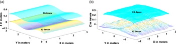
of the Rover. Therefore, one C.G pose information is sufficient to draw the Rover and calculation of wheel velocities. These pose data are saved with an increment of 0.03 m while moving on terrain, which results in a discrete point cloud called CG-Space, as shown in Figure 5 for sine and uneven terrains.
Mesh grid form of terrain with corresponding CG-Space of Rover.

3.3. Obstacles
Obstacles are shown as circular regions on CG-Space, which can be static (denoted by a purple color circle) or dynamic (denoted by a pink color circle). The position of each obstacle
 ${O_i}$
at time t is written by
 ${h_{{O_i}}}\left( t \right) = \left( {{x_{{O_i}}}\left( t \right),\;{y_{{O_i}}}\left( t \right),\;{\phi _{{O_i}}}\left( t \right)} \right)\;$
at obstacle’s center point. The random obstacles can change their heading within the angular bound of ±90°. The velocity of the obstacle
 ${O_i}$
is assumed as a sinusoidal function of heading angle, which is specified by
 \begin{align}{V_O}_i = {k_1}\cos \left( {{\phi _{{O_i}}}\left( t \right)} \right)\hat i + {k_2}\sin \left( {{\phi _{{O_i}}}\left( t \right)} \right)\hat j + {V_z}\left( {{Z_{CG}}} \right)\hat k\end{align}
Here, the constants
 ${k_1}\;\& \;{k_2}$
are chosen with speed proportional to the Rover’s motion on CG-Space and terrain dimensions. The velocity in Z direction (
 ${V_z}$
) is dependent on the change in X and Y direction such that the obstacle center lies on CG-Space. The planner has the information of the obstacles and the Rover for the upcoming two steps to avoid the collision. Obstacles traverse over CG-Space along arbitrary paths within the boundaries.
3.4. Target
In this work, only one target exists in the dynamic path planning problem, which can be taken as a stationary location or randomly moving point within the defined border of the Rover CG-Space. The position and direction of the movement of the goal can be changed arbitrarily. The configuration of the target at time t is shown by
 ${h_T}\left( t \right) = \left( {{x_T}\left( t \right),\;{y_T}\left( t \right)} \right)$
over CG-Space. The depth information in Z-coordinate is obtained using data points of CG-space.
4. CG-Space-based RRT* replanning: A 3d tool for obstacle avoidance
RRT [Reference LaValle37] is one of the most popular sampling-based methods due to its rapid incremental searchability over the nonconvex and high dimensional configuration space. RRT does not face the local minima issue. However, the path found through RRT nodes lacks smoothness and has a bigger optimized length. The RRT* algorithm improves the optimality of the RRT significantly. It has been proven to generate an asymptotically sub-optimal solution [Reference Karaman and Frazzoli38]. RRT* calls an additional local neighborhood planner to minimize the node connection cost in the search tree. However, such algorithms require modifications to deal with the dynamic uneven environment, where the location of goal and obstacle can change over time. In this study, we are dealing with the All-Terrain Rover. Instead of planning the path on the ground, the Rover center of gravity path avoids time-consuming wheel-terrain interaction optimization. CG-Space contains the depth information corresponding to any given (x, y) location. The dynamic obstacle is defined as a local polygonal region over CG-Space. The position and velocity of the obstacle are defined at the center of this region. The initialization of a random obstacle is such that the Rover can replan its path around the obstacle. A detection range is applied in the simulation to initiate the replanning process in the case of obstacle detection.


The moving obstacle must be known to the planner for a minimum of two time steps of the simulation to determine the replanning direction. It means that the planner knows the current location and the next move of a randomly moving obstacle. After getting the Rover path over CG-Space, the Rover traverses the original path by selecting the next node toward the goal until the path is obstructed by a randomly moving obstacle region in CG-Space. The Rover has to dynamically replan its route around the obstacle using the remaining valid nodes of the RRT* space tree. This obstructed portion of the existing path is replanned by rewiring the original space tree while invalidating space tree collision nodes. Then, the Rover changes its heading toward the first node of a rewired portion of the updated path. This process continues until the goal node is reached. Algorithm 2 describes the rewiring subroutine. Figure 6 demonstrates the rewiring process.
Rewiring the invalid path via existing tree nodes in the presence of a randomly moving obstacle.

5. Simulation results
The simulation results are performed over various 3D terrains by three separate dynamic scenarios: Target following, Moving obstacle with simultaneous tree growth, Moving obstacle with rewiring space tree to avoid the collision. The obstacles are presented as simple circular-shaped regions over CG-Space of distinct even and uneven terrains. In simulations, the maximum number of space tree nodes is 1500 for the RRT* algorithm. The step size of space tree growth is 0.03 m. The size of the obstacles over CG-Space is inflated with half of the Rover size (0.3 m) in order to consider the effect of the Rover size on motion path selection. Simulations have been carried out using MATLAB 2018b on an Intel(R) CoreTM i7-8700 processor with 16 GB RAM running at 3.2 GHz.
5.1. Target following
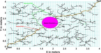
In order to deal with the dynamic goal location, there is no change required in the basic structure of RRT* growth or environment exploration process because it is already random in all directions. The only path-finding links on the space tree will change for moving goal in the existing space tree but with different branches according to the current location from goal to start. Figure 7 shows the way RRT* planner searches the path in space tree backward from the goal to start as a red line in top view. The space tree exploration is random in direction, not goal bias. If the goal location changes, the only tree connection from the goal to the start node will change. The space tree has nodes with defined connections to other nodes (each node has the nodes number of its parent node and all children nodes), which helps reconnect the goal to start from any side.
Top view of a path between the target location from the start node in the presence of an obstacle.

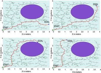
Figure 8 shows the simulation result on uneven terrain with one fixed obstacle and moving goal. The path connections automatically change with the movement of the goal location.
Finding a path to achieve the target location from the current node in the presence of a fixed obstacle: green line shows the path followed by Rover toward the goal, the red dot shows Rover current position, the blue dot shows the current goal position, and the blue line shows the path of moving goal.

5.2. Obstacles avoidance with moving obstacle on a predefined trajectory and fixed goal
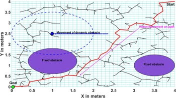
One way to deal with a moving obstacle is to grow the RRT* tree according to the current location of the obstacle in each iteration. This method does not need a rewiring planner, and it is only applicable for a simple and predefined motion of an obstacle. Still, such a method cannot handle too fast obstacles as adding a node takes finite time in milliseconds, and time increases as the RRT* space tree grows. This method has limitations in exploring the narrow regions because the space tree cannot grow at some places due to the changing locations of obstacles. The simulation result is shown in Figure 9. Here, the blue dot shows the center of the obstacle moving on a straight with a dashed circular influence zone around it.
Path toward the target node from the start node in the presence of a known moving obstacle.

5.3. Randomly moving obstacle avoidance for fixed goal problem
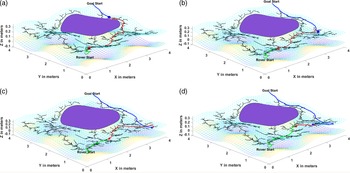
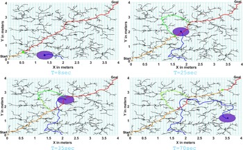
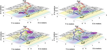
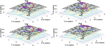
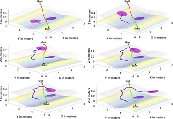
RRT* rewiring method finds the connection between the two portions of the space tree left disconnected due to the sudden introduction of some moving obstacle. The rewiring procedure is valid only when there is a connection among any pair of children nodes less than or equal to the step size of tree growth. Otherwise, the regrowth of the space tree is required. To avoid regrowth, the dynamic planner should have a grown-up tree with enough node connections to rewire. The rewiring time depends on the number of children considered for rewiring. However, it is in milliseconds. Figure 10 shows the top view of the dynamic rewiring process with a randomly moving obstacle, where the yellow line shows the traveled path by the Rover, the green dot shows the Rover’s current position. The purple circular region on CG-Space shows the current random obstacle position. The green line shows the rewired path portion over the red-lined original path toward the goal. Figures 11 and 12 show the real-time 3D movement of the Rover toward the goal in the presence of one fixed obstacle and rewiring of the path to avoid expected collision from a randomly moving obstacle. The green line shows the path followed by Rover toward the goal. The yellow dot shows the Rover’s current position. The pink circular region on CG-Space shows the current random obstacle position. The yellow line shows the rewired path toward the goal.
Finding a path to reach the target location from the current node in the presence of a randomly moving obstacle on the CG-Space over flat terrain.

Finding a path to reach the target location from the current node in the presence of a fixed obstacle and a randomly moving obstacle on the CG-Space over sine terrain.

Finding a path to reach the target location from the current node in the presence of a fixed obstacle and a randomly moving obstacle on the CG-Space over rough terrain.

RRT* space tree growth takes 10 s (for 500nodes) to 10 min (approx 5000 nodes). Rewiring takes 0.001–0.1 s depending upon how close the required connection exists from the rewiring point but regrowing the tree is computationally costly and slow. As compared to the 2D replanning work done on RRT* [Reference Connell and La39] in literature, this study shows a successful implementation in 3D dynamic environments. Regrowth of the space tree during dynamic planning is not considered in this work. Since RRT* finds the path backward, so it requires the whole rewired path from the goal to the current location for further movement, but it does not require the environment in grid form or continuous form. The second major issue of RRT* planning is the path smoothness, which can be tackled by a separate path smothering procedure after getting the path.
5.4. Comparison with PSO-based replanning over CG-Space
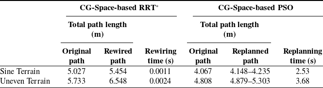
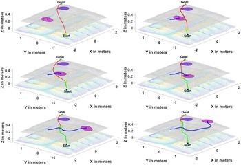
For better comparison, path replanning is done on the same kind of Rover with different algorithms. We plan/replan the path using PSO over CG-Space with dynamic penalty updates to avoid dynamic obstacles. Simulations run on 150 particles with maximum iterations for the primary evolution of particle swarm (maximum number Iteration is 50) before the Rover and obstacles move in CG-Space, which takes 5–10 s depending upon the terrain and initial environment. Later, the dynamic penalty of each particle in the swarm has been evolved to avoid collision with dynamic obstacles. A maximum number of iterations for the dynamic evolution of particle swarm is taken as 15. The details of the algorithm and its implementation over CG-Space are presented in the conference paper [Reference Katiyar and Dutta40]. Upon comparing the path quality and computational load, it is found that PSO takes more time (2–3 s) than the sampling-based algorithms, as it is also optimized during replanning. The Rover also cannot move until the dynamic planner replan the whole path from current location to goal. The planner updated the current path if any moving obstacles hinder the path between the Rover and goal irrespective of collision. PSO provides a smooth path to move directly, but it requires a continuous environment. Although the path is smooth and short, the planner sometimes unnecessarily updates the path even if there is no possible collision exits. A few results are shown in the figures (Figs. 13 and 14) below. In order to compare more precisely, the same terrain arena has been taken with one fixed obstacle and another moving obstacle. The path of the moving obstacle in Figure 13 is the same path traced by the random motion of the obstacle in Figure 11. Similarly, the path of the moving obstacle in Figure 14 is the same as the path created by the random motion of the obstacle in Figure 12. Since all the environment and obstacle conditions are the same, we can easily compare the path length, smoothness, and replanning time between these two algorithms, as given in Table I below. PSO-based path is smooth because it is optimized using the objective function containing the path length and penalty value. Hence, the total path length value obtained by PSO is smaller than the path generated over the RRT* space tree nodes. However, the replanning time is significantly high in the case of PSO as compared to RRT* due to optimization involved in dynamic penalty updates. Since PSO replans the path using the particles’ dynamic penalty value if the shortest path between the Rover’s present position and the goal is obstructed by the moving obstacles, regardless of the likelihood of collision, as shown in Figures 15 and 16.
Finding a path to reach the target location from the current location of the Rover using modified PSO in the presence of a fixed obstacle and a randomly moving obstacle on the CG-Space over sine terrain (the yellow dot is the current position and the green line is the traced path by the Rover).

Comparison between the CG-Space-based rewiring in RRT* nodes and replanning in PSO swarm for collision avoidance in a dynamic environment.

Finding a path to reach the target location from the current location of the Rover using modified PSO in the presence of a fixed obstacle and a randomly moving obstacle on the CG-Space over uneven terrain (the yellow dot is the current position and the green line is the traced path by the Rover).

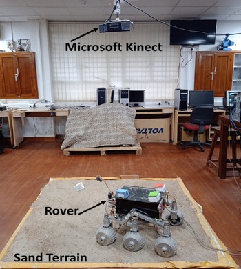
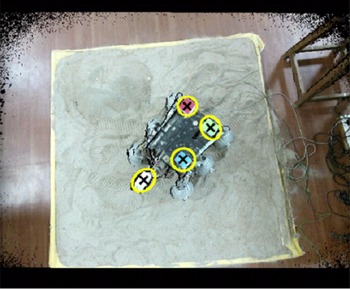
Experimental setup containing sand terrain, Rover, and an overhead Kinect V2 camera for tracking.

Overhead Kinect V2 camera tracks the CG of Rover using three colored markers and a separate white marker showing end-effector position, which can also be used as a point on obstacle if end-effector is not in use.

That is why the replanning path length is obtained in range in PSO-based dynamic path planning. Thus, computational load is also increased due to replanning the path whenever the moving obstacles obstruct the shortest path between the current position of the Rover and the goal. Thus, instead of having the advantage of a shorter and smoother path, PSO lags in the real-time dynamic response required for online replanning of the path when a collision is expected.
5.5. Experimental setup
The Rover has been experimentally evaluated for moving obstacles on uneven terrains made of rock and sand. Currently, the terrain bed has a size of 1.65 m × 1.6 m (Fig. 15). The scanned terrain data using Kinect V2 sensor were converted into mesh grid form, used for simulation purposes and generating the CG-Space. The Rover contains ten motors for movement (six drive Maxon motors with specification EC MAX 30, 40 W, 12 V DC and four steering motors with specification EC MAX 32, FLAT MOTOR, 15 W, 12 V DC). Each motor is equipped with an EPOS motor controller that is connected to a central PC. Some real pictures of experiments are shown below:
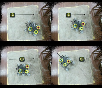
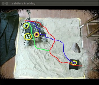
The path planning/replanning simulations run on the central PC, and corresponding path nodes data are converted into wheel velocities using the Rover kinematics model to move the Rover on the path. The color-based marker detection system with four markers (refer to Fig. 16) is used to obtain the pose of the rover while in motion using the Kinect V2 sensor mounted on the top of the rover and provides screenshots of the motion. The white marker is usually equipped to get the position of the end-effector. Since in dynamic replanning, we are only considering the mobile base of the Rover, not the manipulator part, so we have used the white marker to detect the location of the moving obstacle. During initial dynamic experimental validations, the Rover avoids an obstacle moving in a known straight line path. Here, the space tree growth is according to the current location of the moving obstacle. Corresponding screenshots of Kinect capture are shown in Figure 17 at four different time-lapses. Here, the start position is near the lower right corner of the image, the goal is located at the upper left corner of the sand arena, and a black square with a white marker is a moving obstacle in the direction of the black arrow.
Overhead Kinect V2 camera tracks the CG of the Rover using three colored markers and a separate white marker showing the centroid of moving obstacle (a two-wheeled robot moving in a straight line).

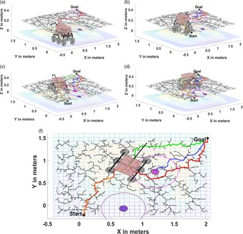
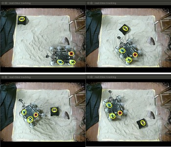
We have included the simulation images in 3D (Fig. 18) and experimental images (Fig. 19) captured by Kinect at four different timestamps to understand better. Here, the model of the actual Rover is also included for a more realistic comparison between simulation capture and Kinect capture. The dotted circles around the fixed and moving obstacle show the influence zone of the obstacle. If the CG of the Rover comes inside these circular regions, then there is a possibility of collision. This influence zone is also considered as an inflated obstacle with the size of the Rover (0.3 m). Thus, the Rover can be simulated as a point robot if the influence zone is considered. Figure 18 shows the simulation screenshots, followed by corresponding experimental frame capture by overhead Kinect in Figure 19. In experiments, the paths generated by RRT* are further smoothened before converting into the wheel velocities to avoid unnecessary sharp turns. Finally, Figure 20 gives the overview of the movement of the Rover and the randomly moving obstacle using colored lines projected over the image captured by Kinect when the Rover is reaching the goal.
Simulation of finding a path to reach the target location from the current node in the presence of a fixed obstacle (purple circle) and a randomly moving obstacle (pink circle) on the CG-Space over rough terrain. (a)-(b) The Rover moving on the original path before collision occurrence and rewiring. (c)-(d) The Rover moving on the rewired path to avoid a collision. (f) In 2D, the Rover changes its direction toward rewired node at the point of rewiring. (The red line shows the original path found by RRT* over CG-Space, the green line shows rewired path, the blue line shows the path of moving obstacle, yellow line show the path traveled by the Rover with a yellow dot at the current CG location of the Rover).

Overhead Kinect V2 camera tracks the CG of the Rover to avoid one fixed obstacle (a stone) and another randomly moving obstacle (a black color two-wheeled robot).

Movement of the Rover on the original (red) path and rewired (green) path along with obstacle movement (blue) in 2D projection over the Kinect captured image.

6. Conclusion and future work
A new dynamic replanning method for a 10 DOF Rover with randomly moving obstacles in CG-Space using RRT* space tree rewiring has been proposed. The proposed RRT*-based replanning is tested for three separate dynamic cases: target following, known moving obstacle avoidance, and randomly moving obstacle avoidance over CG-Space. In the moving goal case, the connection between the current goal and the Rover location changes over time within the same space tree. In the moving obstacle case, some portion of the space tree becomes invalid for obstacle avoidance, and the shortest connection between two subsections of the tree is obtained by rewiring subroutine. If the rewiring planner is not considered, then the space tree has to grow according to the current location of the moving obstacle, but it requires a slow movement of an obstacle. Results show that the rewiring time of the proposed algorithm is in the range of 0.001–0.1 s, depending upon how close the required connection exists from the rewiring point. The proposed dynamic planner is compared with the particle swarm optimization (PSO)-based planner. It is found that PSO takes more time (2–3 s) than the time taken by RRT* rewiring (0.001–0.003) due to optimization during PSO replanning. However, the PSO planned path is better than the RRT* rewired path in terms of length and smoothness. It is also observed that RRT* only rewires when it finds any collision. In contrast, the PSO replans when the obstacles obstruct the shortest path between the current location and the goal, even if there is no possibility of collision. Hence, it can be concluded that instead of having the advantage of a shorter and smoother path, PSO lags in the real-time dynamic response.
The scope of this work will expand in the future to implement rewiring/replanning in the presence of a moving goal location with random obstacles. This 3D dynamic replanning study will benefit cooperative sensing in multiple Rover systems and target tracking in cluttered environments. This work does not incorporate the regrowth of the RRT* space tree during the replanning stage, so modifications in the dynamic growth of the search tree are another area of improvement.
Disclosure
Both the authors contributed to this research, and Ms. Shubhi Katiyar has received a scholarship from Visvesvaraya Ph.D. Fellowship from the Ministry of Electronics & Information Technology (Unique Awardee Number is MEITY-PHD-1779) during this research work.