I. INTRODUCTION
The magnetic coupling coefficient is a very important parameter determining the performance of inductive power transfer (IPT) systems [Reference Boys, Covic and Green1–Reference Li, Hu, Covic and Tang3]. The output power of an IPT system can be quantified as a function of the magnetic coupling coefficient k by [Reference Covic and Boys4],
 $${P_{out}} = {V_1}{I_1}{k^2}{Q_s}\comma \;$$
where (V 1 I 1) is the volt–ampere of the primary side, and Q s is the quality factor of the secondary circuit.
Currently, the magnetic coupling coefficient is measured manually using LCR meters [Reference Hesterman5–Reference Agbinya9]. However, the method can only be used offline, so it does not work for live IPT systems. The actual magnetic coupling coefficient often varies in practical operation, particularly for loosely coupled IPT systems having large air gap variations [Reference Budhia, Covic and Boys10–Reference Stielau and Covic12]. It is important to monitor the real-time magnetic coupling condition of an IPT system for its power flow control [Reference Wang, Hu and Budgett13].
This paper proposes a method for determining the magnetic coupling coefficient of IPT systems during operation. The proposed method uses the voltage and current ratios, which can be easily obtained from open-circuit and short-circuit tests.
II. EXISTING METHODS
There are mainly two methods widely accepted for determining the magnetic coupling coefficient of the coupled coils of IPT systems [Reference Hesterman5]. The first one is based on the measurements of self and leakage inductances, which can be expressed by
 $$k = \sqrt {1 - \left( \displaystyle{{L_{lk1}} \over {L_1}}\right) } \; \qquad \; \; {\rm or}\qquad \; k = \sqrt {1 - \left( \displaystyle{{L_{lk2}} \over {L_2}}\right) } \comma \;$$
where L 1 and L 2 are the self-inductances of the primary and the secondary coils measured at each coil when the other coil is open; and L lk 1 and L lk 2 are the leakage inductances measured at each coil when the other coil is shorted.
The second method is a series-aiding/series-opposing approach, which can be expressed by
 $$k = \; \displaystyle{{{L_{sr + }} - {L_{sr - }}} \over {4\sqrt {{L_1}{L_2}} }} = \displaystyle{M \over {\sqrt {{L_1}{L_2}} }}\comma \;$$
where L sr+ = L 1 + L 2 = 2M is measured when the total inductance of the primary and secondary coils are connected in series with aiding polarities; and L sr− = L 1 + L 2 − 2M is measured when the two coils are connected in series with opposing polarities.
III. THE PROPOSED METHOD
Unlike the existing methods that are based on off-line measurements, the new method determines the magnetic coupling coefficient of the coupled coils by online measurements of the voltage and current ratios, which can be expressed by
 $$k = \sqrt {\displaystyle{{\left\vert {{V_{oc}}} \right\vert } \over {\left\vert {{V_1}} \right\vert }}.\displaystyle{{\left\vert {{I_{sc}}} \right\vert } \over {\left\vert {{I_1}} \right\vert }}} \comma \;$$
where V oc is the open-circuit voltage of the secondary coil when the voltage of the primary coil is V 1, and I sc is the short-circuit current flowing through the secondary coil when the current of the primary coil is I 1.
It should be noted that in IPT systems, the open-circuit voltage (V oc ) and the short-circuit current (I sc ) are the two fundamental parameters used to determine the performance of the secondary power pickup and power transfer capability analysis [Reference Zaheer, Covic and Kacprzak11, Reference Boys, Elliott and Covic14–Reference Abdolkhani, Hu, Moridnejad and Croft16]. The results of these tests can then be advantageously used to determine the magnetic coupling coefficient of the system from (4).
A) Theoretical proof
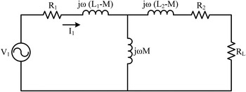
The two coupled coils of an IPT system can be modeled with a T-equivalent circuit as shown in Fig. 1.
T-equivalent circuit of two magnetically coupled coils.

From this model, the open-circuit voltage (when R L = ∞) and short-circuit current (when R L = 0) can be expressed as
 $${V_{oc}} = {V_1}.\displaystyle{{j\omega M} \over {{R_1} + j\omega \, \lsqb M + \lpar {L_1} - M\rpar \rsqb }}\comma \;$$
 $${I_{sc}} = {I_1}.\displaystyle{{j\omega M} \over {{R_2} + j\omega \, \lsqb M + \lpar {L_2} - M\rpar \rsqb }}.$$
From (5) and (6) a voltage gain G v as a ratio of V oc and V 1, and a current gain G i as a ratio of I sc and I 1, can be expressed as following:
 $$\left\vert {{G_v}} \right\vert = \displaystyle{{\left\vert {{V_{oc}}} \right\vert } \over {\left\vert {{V_1}} \right\vert }} = \displaystyle{{\omega M} \over {\sqrt {{R_1}^2 + {{\lpar \omega {L_1}\rpar }^2}} }}\comma \;$$
 $$\left\vert {{G_i}} \right\vert = \displaystyle{{\left\vert {{I_{sc}}} \right\vert } \over {\left\vert {{I_1}} \right\vert }} = \displaystyle{{\omega M} \over {\sqrt {{R_2}^2 + {{\lpar \omega {L_2}\rpar }^2}} }}.$$
These two gains can be further expressed using the quality factors of the primary coil (Q 1 = ωL 1 /R 1) and the secondary coil (Q 2 = ωL 2 /R 2),
 $$\left\vert {{G_v}} \right\vert = \displaystyle{{M/{L_1}} \over {\sqrt {1/{Q_1}^2 + 1} }}\comma \;$$
 $$\left\vert {{G_i}} \right\vert = \displaystyle{{M/{L_2}} \over {\sqrt {1/{Q_2}^2 + 1} }}.$$
In a practical IPT system, coil quality factors are normally designed to very high (Q 1 and Q 2 ≫1). Thus, (9) and (10) can be simplified as
 $$\left\vert {{G_v}} \right\vert = \displaystyle{M \over {{L_1}}}\qquad {\rm \; and}\qquad \; \left\vert {{G_i}} \right\vert = \displaystyle{M \over {{L_2}}}.$$
From (11) it can be proven that the magnetic coupling coefficient k can be determined by (4), which can also be expressed by the voltage and current gains,
 $$k = \displaystyle{{\rm M} \over {\sqrt {{L_1}{L_2}} }} = \sqrt {\left\vert {{G_v}} \right\vert \times \left\vert {{G_i}} \right\vert } {\rm \; } = \sqrt {\displaystyle{{\left\vert {{V_{oc}}} \right\vert } \over {\left\vert {{V_1}} \right\vert }}.\displaystyle{{\left\vert {{I_{sc}}} \right\vert } \over {\left\vert {{I_1}} \right\vert }}} .$$
B) Simulation and practical verifications
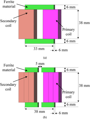
To verify the proposed method, a closely coupled setup similar to a traditional transformer, and a loosely coupled setup with an air gap of 5 mm are built. Fig. 2 shows their three-dimensional (3D) finite-element models developed by JMAG package. The practical setups are built with the same geometries wound around the U-shape ferrite cores as the simulated model (see Fig. 2). In this research, the simulation and experiments were accomplished at 5 W output power from the power pickup as an example for verification. It should be noted that the actual layout of the magnetic structure and the power level of IPT systems can vary depending on specific application and load requirements.
3D finite-element models: (a) un-gapped setup and (b) gapped setup.

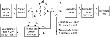
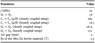
Table 1 shows the system parameters for simulation study and practical experiments. The magnetic coupling coefficient is obtained from the finite elements simulation for both setups. Then practical testing is performed using the traditional self and leakage inductances offline measurements method. The offline measurement is conducted by disconnecting the coils from the circuit and measuring the inductances of both side coils individually using an LCR meter and then calculating the magnetic coupling coefficient between them from (2). Finally each setup is driven by a high-frequency power converter, and the magnetic coupling coefficients are determined using the proposed method. The primary side voltage and current are measured directly across the primary coil using voltage/current probes and an oscilloscope (Model: DSO5054A Agilent). As the operating frequency of circuit is only at kHz levels and the impedance of the measurement probe is very high, the effect of the probe connection to the circuit on the system tuning is negligible. On the secondary side, when the pickup circuit and the load are in operation, they are disconnected for a short time for getting the reading using the two added switches S 1 and S 2 as shown in Fig. 3. As practical power pickups have filters at the output with high time constants [Reference Boys, Covic and Green1, Reference Ping and Hu17, Reference Xu, Boys and Covic18], the effect of short time disconnection from the pickup coil on the output voltage would be very small.
The proposed method for measuring the coupling coefficient k.

Systems specifications.

There is another measurement method that has been proposed in [Reference Lenaerts and Puers19], which requires the values of the inductances as well as the capacitances of the system for the initial measurements, and then the contribution of the capacitance is subtracted from the calculated results to separate the contribution of the inductive components. The proposed method determines the magnetic coupling using the voltage and current ratios (V oc /V 1 and I sc /I 1) without the inductances values, and it does not need to involve the capacitances of the system, making online measurement of the coupling coefficient possible.
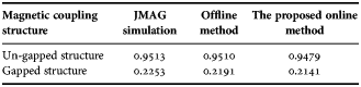
The results are listed in Table 2, which shows a very good agreement between the simulation, offline and the proposed online method. This signifies that accurate magnetic coupling coefficient can be obtained using the proposed method.
Magnetic coupling coefficient (k) results.

IV. CONCLUSION
This paper has presented an online method for determining the magnetic coupling coefficient between two coupled coils for IPT applications. It has been found that the real-time magnetic coupling coefficient can be obtained by online measurements of the open-circuit voltage and short-circuit current of IPT systems during practical operation. The results from the finite-element simulation and practical experiments have shown that the proposed method can be used to accurately determine the magnetic coupling coefficients of both closely and loosely coupled coils with high-quality factors.
 A. Abdolkhani graduated from Dezful University, Iran, with B.E. degree in Electrical Engineering in 2000. After completing his B.E. he worked in the industry for about 6 years in Iran. He received his M.T. degree from the College of Engineering/University of Pune (COEP), India, in Electrical Engineering in 2008. He is currently working toward his Ph.D. with the power electronics group of the University of Auckland, New Zealand. His research interest includes IPT (Inductive Power Transfer) technologies and mainly focused on Contactless Slipring Systems (CSS) for rotary applications. Besides the academic, Ali is working with the team of PowerbyProxi Ltd. on different types of wireless power transfer systems. He holds five patents in wireless/contactless power transfer technology, published about 20 international journal and conference papers.
 A.P. Hu graduated from Xian JiaoTong University, China, with BE and ME degrees in 1985 and 1988, respectively. He received his Ph.D. degree from the University of Auckland in 2001 before he worked as a Lecturer, Director of China-Italy Cooperative Technical Training Centre in Xian, and the General Manager of a technical development company. He holds more than ten patents in wireless/contactless power transfer and microcomputer control technology, published more than 130 referred journal and conference papers, authored the first monograph on wireless inductive power transfer technology, and contributed four book chapters on inductive power transfer modeling/control and electrical machines. Patrick is currently the Director of Graduate Studies in the Department of Electrical and Electronic Engineering, the University of Auckland, New Zealand, and also a guest professor of ChongQing University. His research interests include wireless/contactless power transfer technologies and application of power electronics in renewable energy systems.