Introduction
3D printing, also called the additive manufacturing (AM) or the rapid prototyping (RP), emerged in the 1980s as one of the most representative techniques of the Third Industrial Revolution; it is also considered as a technique to drive rapid world development in many industrial applications [Reference Kennedy, Christ, Evans, Arey, Sweet, Warner, Erikson and Barrett1, Reference Ozbolat, Peng and Ozbolat2, Reference Eisenmenger, Wiggins, Fults and Huo3]. In biomedicine, 3D printing can be used to make bone substitutes and frameworks with good biocompatibility (BC) [Reference Teixeira, Aprile and Kelly4, Reference Bergmann, Lindner, Zhang, Koczur, Kirsten, Telle and Fischer5, Reference Loo, Chua and Pumera6]. In new energy resources, electrode structure of lithium ion battery and some functional components and parts can be made by using 3D printing [Reference Scheithauer, Bergner, Schwarzer, Richter and Moritz7, Reference Campbell and Ivanova8, Reference Woosley, Abuali, Kelkar and Aravamudhan9]. In mold processing, optimization of mold design and shortening of research and development cycle are possible by 3D printing [Reference Dowler, Heike, Schuppich, Luis and Tanya10]. 3D printing includes the following processes: selective laser sintering (SLS), fused deposition modeling (FDM), stereolithography appearance (SLA), laminated object manufacturing (LOM), and three-dimensional printing (3DP) [Reference Liu, Wang, Wu, Cui, Guo and Yan11]. FDM process is advantageous for 3D printing because no laser is needed, and low melting point polymer filaments such as polylactic acid (PLA) and acrylonitrile butadiene styrene (ABS), expensive in cost and maintenance, small in size, and flexible as a desktop tool, enables AM of multiphase composite materials available by multi-jet and multi-channel feeding so as to obtain the multifunctional components [Reference Jayanth and Senthil12]. It is worth mentioning that NASA sent an FDM 3D printer in outer space for the first time in 2014, and the printer printed spanners for maintenance and repair of the space station [Reference Wall13]. Moreover, NASA is planning to launch a second 3D printer to outer space to recycle 10,000 sealed plastic bags abandoned in outer space by NASA [Reference Anderson14].
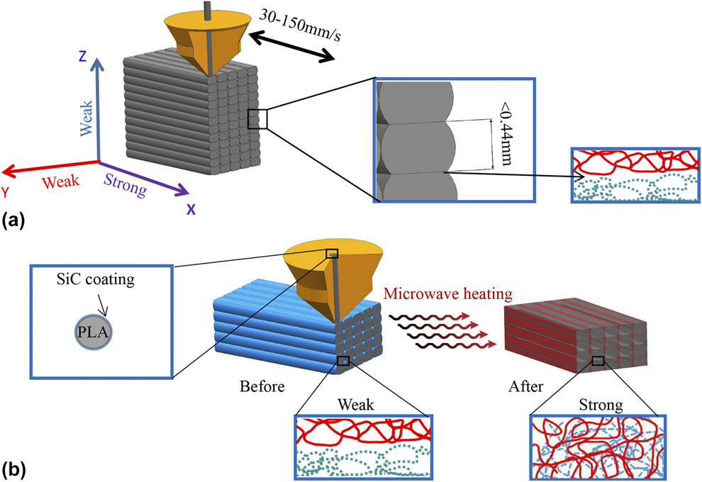
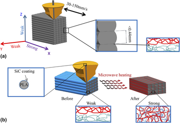
As a biodegradable plastic with good BC, PLA is derived from renewable sources such as starch and sugarcane, and it is highly popular in bone tissue engineering [Reference Wang, Gramlich and Gardner15]. Therefore, PLA is a material widely used for FDM at present. It is not something to be ignored that fusion of filaments in the X direction of the PLA 3D parts leads to good mechanical properties. However, the fuse is disconnected with the macroscopic interface in the fuse-distributed Y and Z directions, with the fuse accumulated layer by layer [Reference Wang, Gramlich and Gardner15, Reference Shaffer, Yang, Vargas, Prima and Voit16] [Fig. 1(a)]. Apparently, the interface is the weakest position of the 3D parts, and it leads to low mechanical performances and anisotropy of the 3D parts. Moreover, the existence of interfaces is decided by FDM process principle, and the interface cannot be removed. Obviously, it is important to improve the bonding properties and mechanical performances of the interface [Reference Wang, Wang, Shen and Wu17]. In the FDM-printed PLA parts, precise and efficient enhancement measures should be taken to improve fusion interfaces within the finite time of interface forming. By this, not only the whole performances and functions of FDM-printed PLA 3D parts can be improved, but also the FDM application is expanded and enriched. Ravi et al. [Reference Ravi, Deshpande and Hsu18] proposed synchronous and local laser heating near the nozzle-layered zone to raise the interfaces temperature above the T g. By this way, mutual interface diffusion of PLA molecule chain was increased and layer interface bonding of FDM-printed PLA parts was highly enhanced. Patanwala et al. [Reference Patanwala, Hong, Vora, Bognet and Ma19] discussed that nucleation and flow of PLA modified by carbon nanotube (CNT), mainly focusing on interface flow state. The results showed that the addition of CNT increased fluidity and crystallinity of interface PLA, which was positive for interface bonding and overall mechanical properties of FDM-printed PLA parts. Levenhagen et al. [Reference Levenhagen and Dadmun20] added a series of synthetic low molecular weight (LMW) PLA components (80.5 K, 50 K, and 100 K) to the bimodal mixture (220 K) PLA to improve the mechanical properties of FDM-printed PLA parts by modifying the degree of cross-linking.
Internal fusion and interface distribution diagram of PLA 3D parts obtained by FDM (a) without SiC coating (b) with SiC-coated PLA filaments and microwave heating.

Nano SiC power devices have great dielectric properties at the frequency range of 8.2–12.4 GHz and high dissipation factor. Therefore, nano SiC is a good microwave absorbing material, which can convert microwave into heat in a short time [Reference Zhao, Zhao and Zhou21]. It is worth mentioning that SiC is a good biocompatible material and is popular for medical implants [Reference Torres-Raya, Hernandez-Maldonado, Ramirez-Rico and Garcia-Ganan22]. This article first introduces the preparation of SiC coating solution and the practice that the solution is applied on the printing filament PLA surface for FDM to gain the SiC/PLA composite filaments after drying. After that, the SiC/PLA composite specimen is printed by FDM, and then the specimen is put into the microwave oven for microwave heating, so that SiC on the fusion interface in the specimen absorbs microwave for heating. At the same time, PLA is remolten on the fusion interface to promote the migration of local PLA molecular chain and the cross-interface entanglement and reduce the influence of the interface. As a result, the mechanical performance of SiC/PLA composite specimen is enhanced precisely and efficiently [Fig. 1(b)].
Results and discussion
Microwave heating
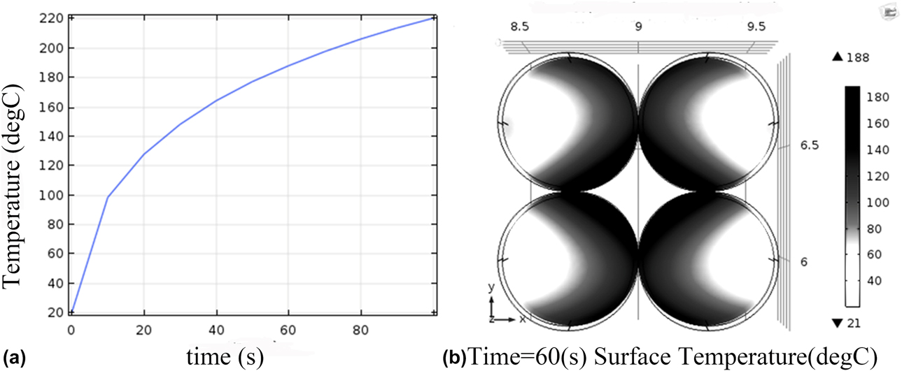
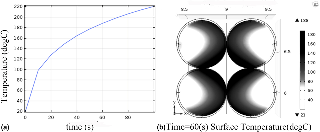
The temperature-rising curve of the fuse interface and the temperature distribution cloud pattern of the entire SiC/PLA composites in the microwave field were obtained by the COMSOL numerical calculation [Figs. 2(a) and 2(b) respectively]. The corresponding electric field as well as temperature field could be obtained with dielectric loss of the SiC uniformly distributed on the PLA matrix surface under the microwave effect. Temperature decreased gradually at a graded distribution from the surface to the inner side of the PLA matrix. The maximum temperature of the surface reached 210 °C with heat transfer of the composite-coated PLA matrix, its thermal convection with air in the microwave oven, and its thermal radiation with the inner wall of the metal waveguide. This provided the necessary condition for microwave heating of the SiC/PLA composite 3D-printed specimen to remelt at the fuse interface. At the same time, it was seen from the temperature rising characteristics curve of the SiC on the filament surfaces that the SiC/PLA composite filament had fast temperature rising within the microwave field. The temperature raised slowly and stably for 17 s, and it reached a maximum temperature of 210 °C in 95 s.
(a) Temperature rising characteristics curve of SiC on the PLA filament surface at 2.45 GHz and 150 W; (b) temperature distribution cloud pattern for the interface in the matrix of the printed part.
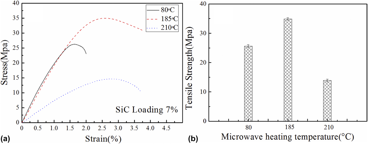
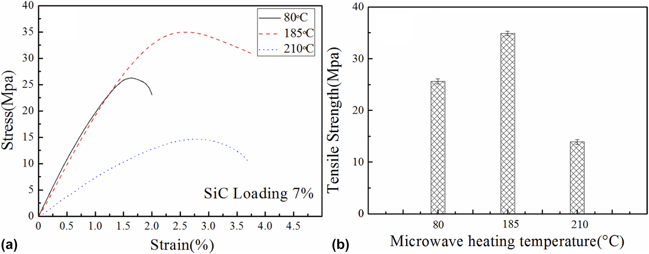
The optimal microwave acting time and temperature should be known based on the calculated results of above data and the basic melting point of 185 °C for the PLA matrix. At first, the SiC/PLA composite tensile specimens with an SiC mass fraction of 7% were treated using the microwave for 10 s at 80 °C, 60 s at 185 °C, and 95 s at 210 °C respectively. The tensile strength of the specimens is shown in Fig. 3(a). The ultimate tensile strength is shown in Fig. 3(b). Obviously, it is seen from the figure that 60 s and 185 °C was the optimal microwave acting time and temperature. It is worth noting that the tensile specimens at 95 s-210 °C was severely deformed. As well, it is worth noting that the thickness of the samples before and after microwave heating has not changed significantly.
(a) Stress–strain curves and (b) tensile strength of 7% microwave heated SiC/PLA composites for 10 s at 80 °C, 60 s at 185 °C, and 95 s at210 °C. Data are presented as mean ± standard deviation.
Tensile test
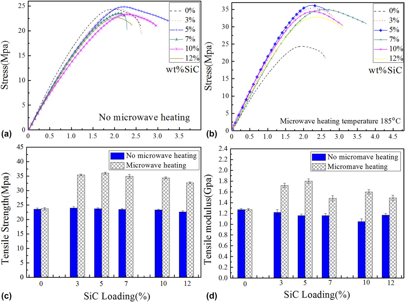
At first, the tensile test was carried out for the SiC/PLA composite tensile specimens with SiC mass fractions of 0%, 3%, 5%, 7%, 10%, and 12% and were not treated by microwave [Fig. 4(a)]. Obviously, the tensile mechanical property of SiC/PLA composite specimens was not enhanced. Their tenacity decreased to some extent, but the specimen with 5% SiC improved slightly in strength. This was because the hard phase SiC particles were not harmonized with the PLA matrix when they were distributed on the soft PLA filament surface. The tensile curves of the SiC/PLA composite tensile specimens with SiC mass fractions of 0, 3, 5, 7, 10, and 12% are shown in Fig. 4(b), when treated by microwave heating. As a result, the PLA specimens without SiC particles had no change in the tensile property, but the SiC/PLA composite tensile specimens with SiC mass fractions of 3, 5, 7, 10, and 12% showed improved tensile property, and the specimen with 5% SiC showed the maximum improvement in strength. This was because the SiC particles distributed on the fusion interfaces absorbed microwave radiation and remelted the PLA matrix at the interfaces and reduced the effect of the interface separation. Moreover, the remelting made a certain number of PLA molecular chains to further cross-bond, and the resulting enhancement was greater than the separation effect of the SiC particles. Figures 4(c) and 4(d) show the tensile strength and tensile modulus for all tensile specimens by microwave heating, respectively. It is seen from the figure that the specimen with 5% SiC heated using microwave had a maximum tensile strength of 36 ± 0.34 MPa and a maximum tensile modulus of 1.8 ± 0.04 GPa [Reference Li, Zhao, Wu, Jiang, Wang, Jiang and Fuh23].
Tensile stress–strain curves (a) before and (b) after microwave heating, as well as the contrast of (c) tensile strength and (d) tensile modulus of SiC/PLA composite specimens, with SiC mass fractions of 0, 3, 5, 7, 10, and 12%. Data are presented as mean ± standard deviation.

Interlayer adhesion test
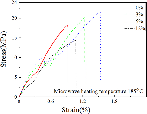
Tensile tests of the SiC/PLA composite interlayer bonding specimens with SiC mass fractions of 0, 3, 5, and 12% heated using microwave are shown in Fig. 5. The interlayer bonding specimens with SiC mass fractions of 3 and 5% had a significantly higher tensile strength, that is, interlayer bonding strength than specimens without SiC. The specimen with 5% SiC had a maximum interlayer bonding strength of 21.6 ± 0.29 MPa [Reference Li, Zhao, Wu, Jiang, Wang, Jiang and Fuh23]. This is due to PLA remelting at the fusion interface of 3D-printed composite parts. Furthermore, both presented a remarkable yielding stage and a sound tenacity. This may be due to the addition of appropriate SiC particles, which acts as nucleating agent and increases the crystallization of PLA. However, the SiC/PLA composite interlayer bonding specimen had the significantly lower interlayer bonding strength and yielding tenacity than the one without SiC. Obviously, the separation effects of excessive SiC content and distribution of all the contents on the interlayer interface can destroy the interlayer bonding.
Stress–strain curves of SiC/PLA composite interlayer bonding specimens with SiC mass fractions of 0, 3, 5, and 12% after microwave heating.

SEM morphology of fracture surfaces
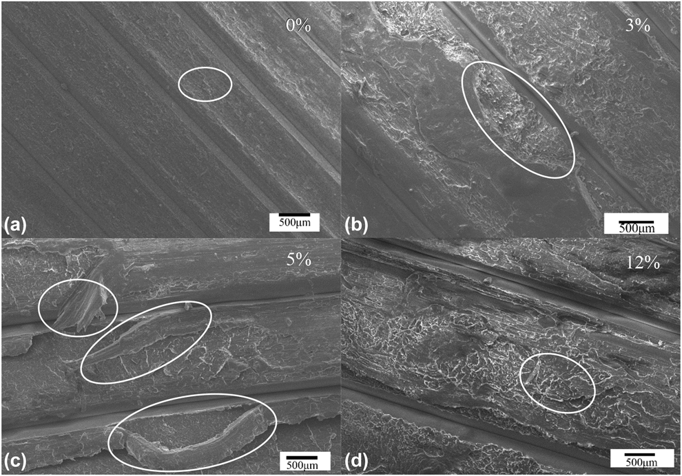
The morphology of fracture surfaces of PLA/SiC composite interlayer bonding specimens with SiC mass fractions of 0, 3, 5, and 12% after tensile test was observed by using SEM as shown in Fig. 6. The morphology of fracture section was clean and complete for the PLA interlayer bonding specimen without SiC after tensile failure [Fig. 6(a)]. This was because fracture occurred on the weakest Z-directional interface of the specimen, where only the bonding of PLA matrix itself occurred within the shortest curing time of 3D printing, and the follow-up microwave heat treatment had no remelting enhancing effect on the matrix without SiC. However, for the PLA/SiC composite interlayer bonding specimens with 3 and 5% SiC, the morphology of their fracture sections gradually presented the tearing and interlaced ductile fractures, as shown in Figs. 6(b) and 6(c). Especially for the specimen with 5% SiC, its tearing fracture crossed the interface into the matrix. This was the same as its maximum tensile strength and tenacity. However, for the SiC/PLA composite interlayer bonding specimen with 12% SiC, its separation effect was far more than the in situ remelting enhancing effect as too many hard phase SiC particles were distributed on the interface, so that there were many brittle cracks distributed on the fracture section of the specimen after tensile failure, presenting a typical brittle fracture feature as shown in Fig. 6(d).
Fracture surfaces of SiC/PLA composite interlayer bonding specimens with SiC mass fractions of (a) 0%, (b) 3%, (c) 5%, and (d) 12% respectively after tensile failure.

Conclusion
The PLA/SiC composite filaments coated with SiC on the surface had better temperature rising characteristics and temperature distribution as SiC absorbed microwave and gained heat in the microwave field. Moreover, the PLA/SiC composite 3D-printed specimens could obtain the optimal in situ remelting enhancing effect on the interface for 60 s at.185 °C. Among the PLA/SiC composite 3D-printed specimens with different SiC mass fractions by microwave posttreatment, the tensile specimen with SiC mass fraction of 5% had the maximum strength of 36 MPa, as 51% better than PLA without SiC. For the interlayer bonding specimens with SiC mass fraction of 5%, their interlayer bonding strength increased to 21.6 MPa to a greatest degree of 18.7% higher than that of the interlayer bonding strength of the PLA specimen without SiC. It should be pointed out that the SiC separation effect was greater than the interface in situ remelting enhancing effect by microwave posttreatment when the SiC mass fraction was as high as 12%, so that the interlayer bonding strength and yielding tenacity decreased significantly against the PLA specimen without SiC. The morphology of fracture sections of PLA/SiC composite 3D-printed interlayer bonding specimens showed the aforementioned mechanical property characteristics. To conclude, the microwave-heated PLA/SiC composite 3D-printed specimens by adding SiC improved PLA filaments are an effective approach for enhancing the strength of FDM-printed PLA composite specimens.
Experiments
Microwave heating
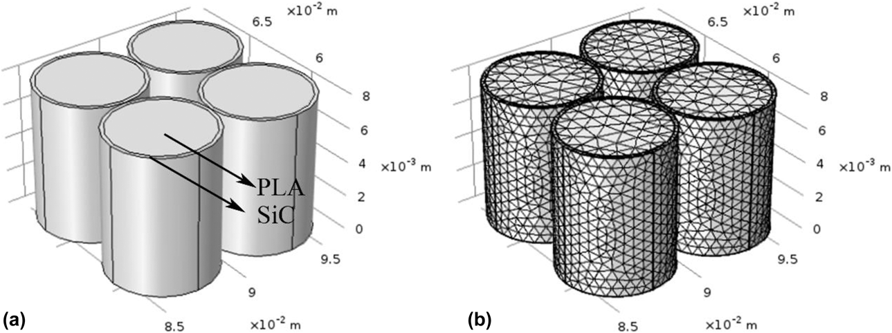
Within the microwave field, only the SiC on the SiC/PLA composite filament surface has dielectric loss and obtained the rising temperature with microwave radiation [Reference Aïssa, Tabet, Nedil, Therriault, Rosei and Nechache24]. In the field, the temperature rising characteristics of fuse interface, where SiC located, and whole temperature distribution of the composite filament were keys for the microwave posttreatment of PLA/SiC composite specimens. The SiC/PLA composite filament model was established in COMSOL [Fig. 7(a)]. The model was divided by the tetrahedral meshes as shown in Fig. 7(b). Meanwhile, the parameters of microwave field, heat transfer field, boundary condition, and corresponding material dielectric loss were set [Reference Patrick and Choyke25, Reference Madelung, Rössler and Schulz26]. On the basis of solving the frequency domain steady state, the temperature rising curve and the whole temperature distribution cloud pattern were obtained for the SiC/PLA composite filament at the internal surface of the microwave field.
(a) SiC/PLA composite filament model established in COMSOL; (b) the tetrahedral meshing model.

The scientific experiment platform for microwave materials (Mobilelab series, Tangshan Nayuan Microwave Thermal Instrument Manufacturing Co., Ltd., Tangshan, China) was used for the microwave heating of 3D-printed specimen obtained by FDM for the SiC/PLA composites. The microwave frequency and power values of 2.45 GHz and 150 W, respectively, were determined by the above the numerical calculations; the microwave acting time and temperature were based on the results of numerical calculations, and the PLA melting point was set at 185 °C. By the verification of tensile experiment, the optimal microwave acting time and temperature were determined finally.
Materials
The PLA filament, purchased from Shenzhen Aurora Technology Co., Ltd. (Shenzhen, China), had the following parameters: diameter, 1.75 mm; density, 1.30 ± 0.05 g/cm3; melting point, 185 °C; glass transition temperature, 80 °C; printing temperature, 195–230 °C; melt flow rate, 5–7 g/10 min (190 °C, 2.16 kg); tensile strength, 25 MPa; tensile modulus, 1.3 GPa; elongation at break, 4%; SiC powder diameter, 100–500 nm; phase, α-SiC; and acetone purity, 99%. PLA powder diameter of 20 μm has the same performance as the filaments mentioned above.
Preparation of SiC/PLA composite filaments
Coated-PLA filaments were produced by first dissolving 50 g of PLA powder in 50 mL of acetone solution, and the solution was fully stirred with a magnetic stirrer for 30 min; then different weight of SiC powder of mass fractions 3%, 5%, 7%, 10%, and 12% was added. After the coating suspensions were stirred, PLA filaments were coated by drawing filaments slowly at a rate of 1 cm/s through the suspension. Finally, the coated PLA filaments were placed in the oven and the filaments were dried for 12 h at 70 °C to obtain the SiC/PLA composite filaments with SiC mass fractions of 3%, 5%, 7%, 10%, and 12% respectively.
Preparation and mechanical testing specimens
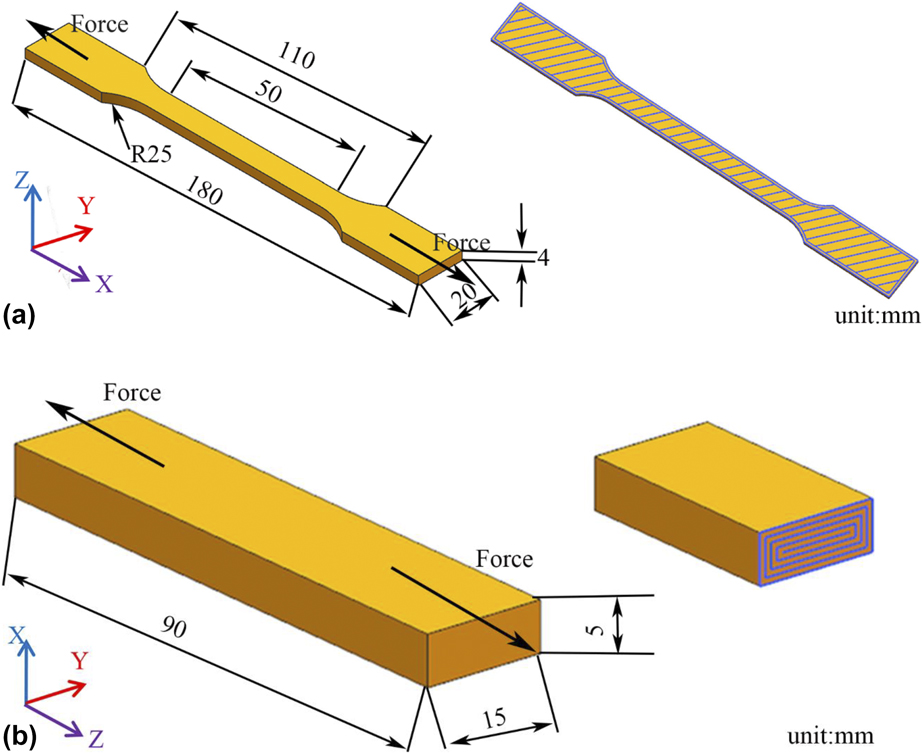
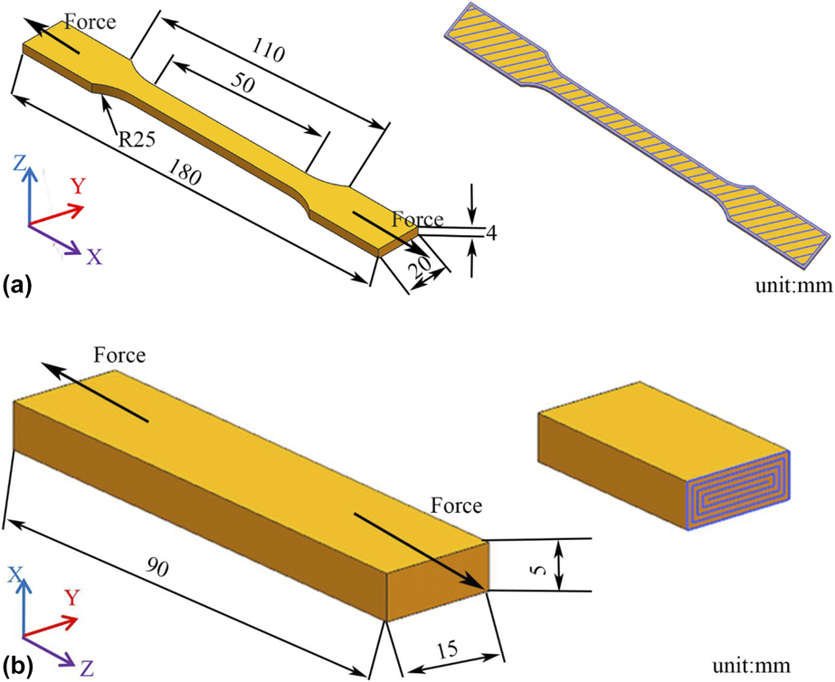
In the 3D Modeling Software UG, the tensile specimen model was drawn according to Tensile Standard ISO 527:1993 for plastics [Fig. 8(a)]. At the same time, the interlayer bonding specimen model was designed by a rectangular solid of 5 × 15 × 90 mm, as shown in Fig. 8(b). The loading direction is shown by the arrow’s direction in the figure when the tensile and interlayer performance tests were tested using the electronic universal testing machine (UTM5305, Shenzhen Sansi Vertical and Horizontal Technology Co., Ltd., Shenzhen, China). The STL data were exported from the model and were read using the special slice software Cura. The key 3D printing parameters were set as: Jet extrusion temperature, 210 °C; printing speed, 40 mm/s; packing density, 100%; base plate temperature, 60 °C; and layer height, 0.2 mm. The Gcode file was generated for the specimen printing control of the FDM 3D printer (A-Shenzhen Aurora, Shenzhen, China). The PLA bare filament and SiC/PLA composite filaments were used to obtain the SiC/PLA composite tensile specimens with SiC mass fractions of 0%, 3%, 5%, 7%, 10%, and 12% and the SiC/PLA composite interlayer bonding specimens with SiC mass fractions of 0%, 3%, 5%, and 12%. The slice-layered direction was the positive direction of the Z axis, while the printing routes in each layer were distributed on the XY plane; the printing route was at an included angle of 45° against the X and Y axes for the tensile specimens [Fig. 8(a)]; the printing route had no included angle against the X and Y axes for the interlayer bonding specimens [Fig. 8(b)]. As the load applying direction was the same as the 3D printing layered direction, the gained tensile strength could be regarded as the interlayer bonding strength.
(a) Tensile specimen model and printing route; (b) interlayer bonding specimen model and printing route.
SEM
Noncoated fracture X sections after tensile failure of the interlayer bonding specimen was observed using the Quanta SEM TM 250 (Quanta 250, Hitachi High-Tech Company, Tokyo, Japan) with 13 kV accelerating voltage.
Acknowledgment
We would like to extend our thanks for the support of the Fundamental Research Funds for the Central Universities of China University of Mining and Technology (2017XKQY008) and Laboratory Open Fund of China University of Mining and Technology.