Nomenclature
Symbols
- CAV
-
Common Aero Vehicle
- DNN
-
Deep Neural Network
- DQN
-
Deep Q Network
- DOF
-
Degree of Freedom
- EKF
-
Extended Kalman Filter
- HTV
-
Hypersonic Technology Vehicle
- HGV
-
Hypersonic Glide Vehicle
- QEGC
-
Quasi-equilibrium Glide Condition
1.0 Introduction
Hypersonic glide vehicles (HGV) flying in near space rely mainly on aerodynamic force for control and have a Mach number greater than 5 [Reference Li, Zhang and Tang1]. The entry phase of the hypersonic glide vehicle has the characteristics of high speed, a wide range of speed change, long-range and high manoeuverable. Typical HGVs are the common aero vehicle (CAV) [Reference Phillips2] and hypersonic technology vehicle (HTV) [Reference Walker, Sherk, Shell, Schena, Bergman and Gladbach3]. In response to the threats posed by hypersonic vehicles, various countries have successively developed anti-missile interception systems such as Aegis and S-400, which greatly weakens the combat effectiveness and penetration capabilities of hypersonic vehicles [Reference Gao, Zhang and Jia4]. To improve the penetration capability of hypersonic vehicles and achieve saturation strikes on targets, it is necessary to develop multi-hypersonic vehicles coordinated strike technology.
The flight process of the HGV is divided into five phases: boot-up, adjustment, initial entry, entry glide and attack down [Reference Liang5]. Among them, the entry gliding phase has the longest flight distance, the largest airspace span, and the most dramatic changes in aerodynamic characteristics. The complexity of the state change during the vehicle’s entry phase will have a huge impact on the terminal guidance phase. Therefore, it is reasonable to conduct time-coordinated guidance of the vehicle in the entry phase, so that multiple vehicles can provide good handover conditions for the coordination of the next terminal guidance phase and finally reach the designated target point at the same time.
The existing entry guidance methods mainly include nominal trajectory guidance and predictive correction guidance. Shen and Lu [Reference Shen and Lu6] obtained the constrained boundary of the bank angle according to the height-speed entry corridor and obtained the nominal trajectory of the gliding phase by designing the bank angle curve that met these requirements. Zhang et al. [Reference Zhang, Chen, Liu, Tang and Bao7] studied the trajectory planning method based on the three-dimensional drag acceleration profile. For predictive correction guidance, based on a consideration of the path constraints, Joshi et al. [Reference Joshi, Sivan and Amma8] used the angle-of-attack and the bank angle as the control variables of the prediction-correction guidance method. However, the above-mentioned guidance methods apply to a single vehicle and cannot be directly used to the coordinated guidance of multi-hypersonic vehicles.
Current multi-vehicle coordinated guidance methods are mostly applied to terminal guidance [Reference He, Wang, Lin and Lei9] or low-speed unmanned aerial vehicles [Reference Beard, McLaint and Goodricht10, Reference Campbell and Whitacre11, Reference Zong, Wang, Shao, Zhang and Yu12]; in terms of multi-missile cooperative guidance, the existing cooperative guidance methods can be divided into a two-layer cooperative guidance architecture and a “leader-follower” cooperative guidance architecture. Zhao et al. [Reference Zhao and Zhou13] proposed a two-layer guidance architecture for the first time, in which the constrained guidance law satisfying the missile flight characteristics was the bottom-level guidance control, and the centralised or decentralised coordination strategy including coordination variables was used as the upper-level coordination control. Zhang et al. [Reference Zhang, Ma and Wang14] proposed the leader-follower cooperative guidance architecture, which selected the reference motion state of the missile according to the coordination requirements, and took the lead missile as the desired reference motion state. By tracking the reference motion state of the leading missile or adjacent ballistics, the reference motion state of the secondary missile gradually adjusted to the expected value, thereby realising multi-missile cooperative guidance. Subsequent research was mostly based on the optimisation of the above two architectures. For stationary targets in the plane, Kumar et al. [Reference Kumar and Ghose15] designed a time-constrained guidance law based on sliding mode control as the bottom layer guidance control, and the upper layer coordinated control was based on the minimum sum of the sliding mode surface deviations of all missiles to obtain cooperative guidance method with expected attack time as average of remaining time. Compared with traditional missiles, HGVs have unique difficulties such as fast flight speed and single control amount. For the hypersonic vehicle entry phase, coordinated guidance can be separated into two types: lateral guidance and longitudinal guidance. For lateral guidance, Liang et al. [Reference Liang, Yu, Ren and Li16] used the shooting method to optimise the longitudinal bank angle profile to meet the terminal distance and height constraints, and laterally through the iterative heading angle corridor width to meet the coordination time constraints. Yu et al. [Reference Yu, Dong, Li, Ren and Lv17] proposed an analytical multi-projectile coordinated entry guidance method. This method divided the entry trajectory into two sections. The first section adopted a plan for the angle-of-attack, and the iterative bank angle satisfied the distance constraint. The second section had a bank angle of zero and the iterative angle-of-attack met the time constraint. But this method was not suitable for HGVs with drastic changes in lift-to-drag ratio. Fang et al. [Reference Fang, Zhang, Kun, Cheng and Huang18] proposed a time-controllable entry guidance law, which used neural networks to predict the remaining flight time and increased the lateral manoeuverability by adjusting the heading angle and corridor width to change the flight time. Zhang et al. [Reference Zhang, Yu, Li and Chen19] proposed a deep reinforcement-based entry cooperative guidance method. The longitudinal lift-to-drag ratio was calculated to obtain the modulus of bank angle based on the high-precision longitudinal analytical solution. In lateral guidance, the DQN algorithm was used to adjust the sign of the pitch angle to control the flight time. The above-mentioned time-coordination guidance algorithms all change the flight time by increasing the lateral maneuverability of the vehicle and increasing the lateral manoeuverability might cause the vehicle to miss the target or result in problems in avoiding obstacles. For longitudinal guidance, Wang et al. [Reference Wang, Guo, Tang and Qi20] proposed a predictive-corrected cooperative guidance law based on the altitude-velocity profile, which adjusted the remaining flight time and distance by adjusting the two trajectory parameters of the profile and further analysed the ability of co-time regulation. Li et al. [Reference Li, He, Wang, Lin and An21] proposed a time-coordination guidance algorithm based on the bank angle profile, the time and range constraints were met by adjusting the parameter values of the bank angle profile, and at the same time by adjusting the lateral error damping coefficient in the lateral direction, and the time adjustment capability was further increased. But the change range of adjustment parameters of the algorithm were too large to put it into real practice. The above two time-coordinated guidance algorithms based on longitudinal guidance have real-time problems due to the large number of integral prediction and it cannot meet the requirements of rapid guidance of hypersonic vehicles at high Mach numbers.
Based on the above analysis, this paper proposes a time-coordination entry guidance algorithm based on deep learning. First, a dual-parameter bank angle profile is developed to suit the requirements of time coordination and to set the groundwork for the vehicle trajectory database’s compilation. Second, a vehicle trajectory database is built, and a framework is developed for a deep neural network (DNN) that satisfies the error criteria to identify the functional relationship between the flight states and the parameters of the profile in longitudinal guidance, which improves the real-time performance of the algorithm. Moreover, the input parameters of the deep neural network contain perturbations in the lift and drag coefficients that significantly improve the algorithm’s resilience. Finally, the extended Kalman filter (EKF) is used to identify the disturbance coefficients online, and to meet the needs of the real flight process, the disturbance coefficients are used as input parameters for the DNN training in the network design.
2.0 Preliminary
2.1 System dynamics
In the entry phase of the vehicle, in order to grasp the main contradiction, the following assumptions are made: the rotation of the Earth is not considered; considering that the longitudinal range of the entry phase is relatively large, the Earth is regarded as a sphere. The 3DOF point-mass dynamics for hypersonic entry vehicle over a non-rotating Earth are described by [Reference Mease, Chen, Teufel and Schonenberger22]:
 \begin{align} \left\{ {\begin{array}{*{20}{l}}{{{\dot r}_i} = {V_i}\sin {\theta _i}}\\[5pt] {{{\dot \lambda }_i} = \dfrac{{{V_i}\cos {\theta _i}\sin {\psi _i}}}{{{r_i}\cos {\phi _i}}}}\\[10pt] {{{\dot \phi }_i} = \dfrac{{{V_i}\cos {\theta _i}\cos {\psi _i}}}{{{r_i}}}}\\[10pt] {{{\dot V}_i} = - {D_i} - g\sin {\theta _i}}\\[10pt] {{{\dot \theta }_i} = \dfrac{1}{{{V_i}}}\left[ {{L_i}\cos {\sigma _i} + \left( {\dfrac{{V_i^2}}{{{r_i}}} - g} \right)\cos {\theta _i}} \right]}\\[12pt] \begin{array}{l}{{\dot \psi }_i} = \dfrac{1}{{{V_i}}}\left( {\dfrac{{{L_i}\sin {\sigma _i}}}{{\cos {\theta _i}}} + \dfrac{{V_i^2}}{{{r_i}}}\cos {\theta _i}\sin {\psi _i}\tan {\phi _i}} \right)\\[10pt] {{\dot t}_i} = 1\end{array}\end{array}} \right.\end{align}
where
 $i$
represents the
 $ith$
vehicle;
 $r$
is the nondimensional radial distance from the Earth’s centre to the vehicle, the nondimensional parameter is the radius of the earth
 ${R_0}$
;
 $\lambda $
and
 $\phi $
are the longitude and latitude;
 $V$
is the Earth-relative nondimensional velocity;
 $\sqrt {{g_0}{R_0}} $
is the nondimensional parameter;
 ${g_0}$
is the gravitational acceleration at sea level;
 $\theta $
is the flight-path angle of the Earth-relative velocity vector;
 $\psi $
is the heading angle of the same velocity vector;
 $t$
is the time of vehicle fight;
 $\sigma $
is the bank angle of the vehicle about the relative velocity vector;
 $L$
and
 $D$
are the nondimensional lift and drag acceleration, they are shown in the Equation (2):
 \begin{align} \left\{ {\begin{array}{*{20}{l}}{L = 0.5S\rho {V^2}{C_L}/m}\\[5pt] {D = 0.5S\rho {V^2}{C_D}/m}\end{array}} \right.\end{align}
where
 $m$
is the vehicle mass;
 $S$
is the vehicle reference area;
 $\rho = {\rho _0}{{\rm{e}}^{ - h/7110}}$
is the atmospheric density,
 ${\rho _0}$
is the atmospheric density at sea level,
 $h$
is the distance from the ground to the vehicle;
 ${C_L}$
and
 ${C_D}$
are the lift coefficient and the drag coefficient, and they are a nonlinear function of the Mach number and angle-of-attack. Aerodynamic data can be obtained from the references [Reference Jorris and Cobb23].
An energy-like variable
 $e$
as the independent variable of the prediction and the input of the DNN:
 \begin{align} e = 1/r - {V^2}/2\end{align}
 \begin{align} \dot e = DV\end{align}
It is clear that
 $e$
is the negative of the specific mechanical energy used in orbital mechanics, and it is a monotonically increasing variable [Reference Lu24].
2.2 Entry trajectory constraints
The typical path constraints of an entry vehicle include the heating rate limit
 ${\dot Q_{\max ,i}}$
, the aerodynamic overload limit
 ${n_{\max ,i}}$
, the dynamic pressure limit
 ${q_{\max ,i}}$
, and they can be expressed as [Reference Li, Hu, Ding, Liu and He25]:
 \begin{align} {\dot Q_i} = {k_{Q,i}}{\rho _i}^{0.5}{V_i}^3 \leqslant {\dot Q_{\max ,i}}\end{align}
 \begin{align} {n_i} = \sqrt {{L_i}^2 + {D_i}^2} \leqslant {n_{\max ,i}}\end{align}
 \begin{align} {q_i} = {1 \over 2}{g_{0,i}}{\rho _i}{V_i}^2 \leqslant {q_{\max ,i}}\end{align}
where
 ${\dot Q_i}$
is the heating rate and
 ${k_{Q,i}}$
is a constant,
 ${n_i}$
is the aerodynamic overload and
 ${q_i}$
is the dynamic pressure. The above constraints are hard constraints for an entry vehicle, and the vehicle also needs to meet the quasi-equilibrium guide condition (QEGC) soft constraint
 \begin{align} {L_i}\cos {\sigma _{Q{\rm{EGC,i}}}} - \left( {V_i^2 - \frac{1}{{{r_i}}}} \right)\frac{{\cos {\theta _i}}}{{{r_i}}} \geq 0\end{align}
where
 ${\sigma _{QEGC,i}}$
is the bank angle of the vehicle in QEGC, generally the value is zero.
The typical final constraints are that the trajectory reaches the final longitude
 ${\lambda _{f,i}}$
and latitude
 ${\varphi _{f,i}}$
at a specified final altitude
 ${r_{f,i}}$
and velocity
 ${V_{f,i}}$
, it can be shown that
 \begin{align} \left\{ {\begin{array}{*{20}{c}}{r({t_{f,i}}) = {r_{f,i}}}\\[5pt] {V({t_{f,i}}) = {V_{f,i}}}\\[5pt] {\lambda ({t_{f,i}}) = {\lambda _{f,i}}}\\[5pt] {\varphi ({t_{f,i}}) = {\varphi _{f,i}}}\end{array}} \right.\end{align}
where
 ${t_{f,i}}$
is the time of the vehicle entry phase,
 ${r_{f,i}}$
is the terminal radial distance from the Earth’s centre to the vehicle,
 ${V_{f,i}}$
is the terminal Earth-relative velocity,
 ${\lambda _{f,i}}$
is the terminal longitude,
 ${\varphi _{f,i}}$
is the terminal latitude. Regarding the question of the entry vehicles guidance, the final constraints of the longitude and the latitude usually transform a distance
 ${s_f}$
from the target location.
Considering the time-coordination problem of multi-hypersonic vehicles, it is also necessary to meet the terminal time constraints, which can be expressed as:
 \begin{align} {t_{f,1}} = {t_{f,2}} = \ldots = {t_{f,i}} = {t_{co}}\end{align}
where
 ${t_{f,i}}$
is the total time of entry flight,
 ${t_{co}}$
is the prescribed coordination time [Reference Li, He, Wang, Lin and An21].
Therefore, the objective of time-coordination entry guidance is based on the 3DOF point-mass dynamics Equation (1) to obtain the adjustment parameters of the bank angle profile that meet the constraints Equations (5)–(10).
3.0 Time-coordination guidance algorithm based on DNN
A traditional predictor-corrector guidance algorithm consists of two parts: longitudinal guidance and lateral guidance. Longitudinal guidance determines the amplitude of the bank angle, and lateral guidance uses the heading angle error corridor to determine the bank angle sign.
The longitudinal guidance is composed of two parts: prediction and correction. There is a large amount of integration in the longitudinal guidance of vehicles, and there are real-time problems that cannot be ignored for hypersonic vehicles. The traditional predictor-corrector guidance algorithm can only predict the remaining distance, and cannot meet the needs of coordinated flight of hypersonic vehicles. During the entry process, there will be aerodynamic parameter disturbances, and the hypersonic vehicle mainly relies on aerodynamic force to achieve the entry mission. The aerodynamic parameter disturbances will have a great impact on the accuracy of trajectory prediction and the successful completion of the entry mission.
To solve the cooperative flight problem of vehicles, this paper constructs an improved bank angle profile, which can accurately predict of the remaining distance and remaining time at the same time, so that multiple vehicles can simultaneously reach the designated target point. For real-time problems, this paper designs the DNN to identify the functional relationship between the flight states and the adjustment paraments of the bank angle profile in the predictor-corrector, thereby effectively shortening the guidance instruction solution time and improving the algorithm real-time react ability. For the robustness problem, in the design of the DNN, the influence of atmospheric disturbance is considered to improve the guidance accuracy of the algorithm, and all the aerodynamic parameters are identified online using the EKF. The algorithm flowchart is shown in Fig. 1.
Flowchart of the proposed time-coordination entry guidance algorithm.

3.1 Angle-of-attack profile design
The control amount of the hypersonic vehicle entry flight phase is the angle-of-attack
 $\alpha $
and the bank angle
 $\sigma $
. Considering the thermal protection requirements of the initial phase of entry and the remaining flight distance requirements, this study adopts the angle-of-attack profile is shown as [Reference Wang, Guo, Tang, Qi and Wang26]:
 \begin{align} \alpha = \left\{ \begin{array}{l@{\quad}l} {\alpha _m} & {V > {V_1}} \\[5pt] \dfrac{\alpha _{L/{D_{\max }}} - {{\alpha _m}}}{{V_b} - {V_a}}\left( {V - {V_a}} \right) + {\alpha _m} & {{V_2} \leqslant V \leqslant {V_1}} \\[10pt] \alpha_{L/D{_{\max }}} & {V < {V_2}} \end{array} \right.\end{align}
where
 ${\alpha _m}{\rm{ }}$
is the maximum angle-of-attack,
 ${\alpha _{L/{D_{\max }}}}$
is the maximum lift-to-drag ratio angle-of-attack,
 ${V_a}{\rm{ }}$
,
 ${V_b}$
,
 ${V_1}$
and
 ${V_2}$
are the set speed value;
 ${V_a} = 6,500m/s$
,
 ${V_b} = 5,000m/s$
,
 ${V_1} = 7,000m/s$
and
 ${V_2} = 5,400m/s$
.
Bank angle profile of two adjustment parameters.

3.2 Dual-parameter bank angle profile design
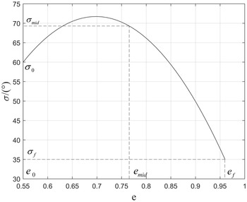
For the initial descent phase of the entry vehicle, the altitude of the vehicle is high, and the aerodynamic effect is small, and it is difficult to effectively control the trajectory of the vehicle. Normally, open-loop guidance with a constant tilt angle is used. After meeting the QEGC, the vehicle moves to the gliding phase. The bank profile of the gliding phase of the HGV is usually designed as a single parameter to meet the needs of adjusting the flight distance. In this section, the vehicle bank angle profile is designed as a parabolic dual-parameter profile, and the time and distance are adjusted at the same time to meet the needs of time-coordinated guidance. For the longitudinal guidance of the gliding phase, the dual-parameter bank angle profile is shown in Fig. 2. In Fig. 2, when the three points on the curve are known, the curve equation can be determined. Therefore, the horizontal and vertical coordinates corresponding to the three points can be used as characteristic values for determining the shape of the curve. When four of the values are determined, the remaining two can be used as adjustment parameters to adjust the remaining flight time and distance. The curve function is defined as shown in Equation (12)
 \begin{align} \left| {\sigma (\textrm{e})} \right| = {k_1}{e^2} + {k_2}e + {k_3}\end{align}
where
 ${k_1}$
,
 ${k_2}$
and
 ${k_3}$
are the bank angle profile coefficient, they can be determined by Equation (13)
 \begin{align} \left\{ {\begin{array}{*{20}{l}}{{\sigma _0} = {{\rm{k}}_1}e_0^2 + {{\rm{k}}_2}{e_0} + {{\rm{k}}_3}}\\[5pt] {{\sigma _{mid}} = {{\rm{k}}_1}e_{mid}^2 + {{\rm{k}}_2}{e_{mid}} + {{\rm{k}}_3}}\\[5pt] {{\sigma _f} = {{\rm{k}}_1}e_f^2 + {{\rm{k}}_2}{e_f} + {{\rm{k}}_3}}\end{array}} \right.\end{align}
where
 ${\sigma _0}$
,
 ${\sigma _{mid}}$
and
 ${\sigma _f}$
are the initial bank angle of the gliding phase, the bank angle at the midpoint, and the terminal bank angle of the gliding phase.
 ${e_0}$
is the initial energy and it is determined by the state of the vehicle after the end of the initial descent,
 ${e_f}$
is terminal energy and it determined by terminal geocentric
 ${r_{f,i}}$
distance and terminal velocity
 ${V_{f,i}}$
,
 ${e_{mid}}$
is the midpoint energy, as shown in the Equation (14):
 \begin{align} {e_{mid}} = ({e_0} + {e_f})/2\end{align}
Equation (13) is a system of linear equations with three variables
 ${k_i}(i = 1,2,3)$
and three equations. Therefore, according to the Cramer’s rule, the value of
 ${k_1}$
,
 ${k_2}$
and
 ${k_3}$
can be obtained:
 \begin{align} {k_1} = \frac{\left| \begin{matrix} {{\sigma _0}}\;\;\;\;\; & {{e_0}}\;\;\;\;\; & 1 \\[5pt] {{\sigma _{mid}}}\;\;\;\;\; & {{e_{mid}}}\;\;\;\;\; & 1 \\[5pt] {{\sigma _f}}\;\;\;\;\; & {{e_f}}\;\;\;\;\; & 1 \end{matrix} \right|}{{\left| \begin{matrix} {e_0^2}\;\;\;\;\; & {{e_0}}\;\;\;\;\; & 1 \\[5pt] {e_{mid}^2}\;\;\;\;\; & {{e_{mid}}}\;\;\;\;\; & 1 \\[5pt] {e_f^2}\;\;\;\;\; & {{e_f}}\;\;\;\;\; & 1 \end{matrix} \right|}},\,{k_2} = \frac{\left| \begin{matrix} {e_0^2}\;\;\;\;\; & {{\sigma _0}}\;\;\;\;\; & 1 \\[5pt] {e_{mid}^2}\;\;\;\;\; & {{\sigma _{mid}}}\;\;\;\;\; & 1 \\[5pt] {e_f^2}\;\;\;\;\; & {{\sigma _f}}\;\;\;\;\; & 1 \end{matrix} \right|}{\left| \begin{matrix} {e_0^2}\;\;\;\;\; & {{e_0}}\;\;\;\;\; & 1 \\[5pt] {e_{mid}^2}\;\;\;\;\; & {{e_{mid}}}\;\;\;\;\; & 1 \\[5pt] {e_f^2}\;\;\;\;\; & {{e_f}}\;\;\;\;\; & 1 \end{matrix} \right|},\,{k_1} = \frac{\left| \begin{matrix} {e_0^2}\;\;\;\;\; & {{e_0}}\;\;\;\;\; & {{\sigma _0}} \\[5pt] {e_{mid}^2}\;\;\;\;\; & {{e_{mid}}}\;\;\;\;\; & {{\sigma _{mid}}} \\[5pt] {e_f^2}\;\;\;\;\; & {{e_f}}\;\;\;\;\; & {{\sigma _f}} \end{matrix} \right|}{\left| \begin{matrix} {e_0^2}\;\;\;\;\; & {{e_0}}\;\;\;\;\; & 1 \\[5pt] {e_{mid}^2}\;\;\;\;\; & {{e_{mid}}}\;\;\;\;\; & 1 \\[5pt] {e_f^2}\;\;\;\;\; & {{e_f}}\;\;\;\;\; & 1 \end{matrix} \right|}\end{align}
where
 ${\sigma _0}$
is designed as a definite value,
 ${e_0}$
,
 ${e_{mid}}$
and
 ${e_f}$
are definite values. The remaining flight distance and time of the vehicle are adjusted by adjusting the values of
 ${\sigma _{mid}}$
and
 ${\sigma _f}$
.
3.3 Determining the amplitude of bank angle based on DNN
Artificial intelligence technology has gradually matured in recent years, owing to advancements in computer software and hardware. The purpose of this paper is to demonstrate how deep learning in artificial intelligence technology can be used to enhance the real-time performance of collaborative guidance algorithms. Proposed by Hinton et al. [Reference Rumelhart, Hinton and Williams27] in 1986, deep learning replaced the original single fixed feature layer with multiple hidden layers. The activation function used the Sigmoid function, and the error backpropagation algorithm was used to train the model. The network obtained by deep learning had a multi-layer structure, and each layer had multiple neurons. The network structure that met the requirements could be obtained by adjusting the weight relationship among the neurons. At present, deep learning is mostly used in low-speed unmanned aerial vehicles [Reference Li and Zhang28, Reference Liu, Wang, Fan, Wu and Wu29] and less in hypersonic aircraft. In this paper, the trained DNN can be used to fit the non-linear mapping relationship between the input and output in the prediction.
After combining the bank angle profile in Equation (12) of the traditional prediction, the remaining distance and time can be obtained by establishing a longitudinal motion equation shown as Equation (16) with non-dimension energy as the independent variable
 \begin{align} \left\{ {\begin{array}{*{20}{l}}{\dfrac{{{\rm{d}}s}}{{\;{\rm{d}}e}} = \dfrac{{\cos \theta }}{{rD}}}\\[10pt] {\dfrac{{{\rm{d}}r}}{{\;{\rm{d}}e}} = \dfrac{{\sin \theta }}{D}}\\[10pt] {\dfrac{{{\rm{d}}\theta }}{{{\rm{d}}e}} = \left[ {L\cos \sigma + \left( {{V^2} - \dfrac{1}{r}} \right)\dfrac{{\cos \theta }}{r}} \right]\dfrac{1}{{D{V^2}}}}\\[10pt] {\dfrac{{dt}}{{de}} = \dfrac{1}{{DV}}}\end{array}} \right.\end{align}
where
 $V = \sqrt {2(1/r - e)} $
.
From the analysis of Equation (16), it can be seen that the input of the DNN is: the non-dimension energy
 $e$
, the nondimensional radial distance
 $r$
, the flight-path angle
 $\theta $
, the bank angle
 $\sigma $
, the nondimensional aerodynamic lift acceleration
 $L$
and drag acceleration
 $D$
. The bank angle is determined by the bank angle adjustment parameters
 ${\sigma _{mid}}$
and
 ${\sigma _f}$
. Considering that the vehicle is in a real flight environment, the aerodynamic parameters are disturbed compared to the those in normal conditions, the lift acceleration and the drag acceleration are affected by the disturbance coefficients
 ${k_{cl}}$
and
 ${k_{cd}}$
. Therefore, the input of the DNN is:
 ${x_{NN}} = [\begin{array}{*{20}{l}}e & r & \theta & {{\sigma _{mid}}} & {{\sigma _f}} & {{k_{cl}}} & {{k_{cd}}}\end{array}]$
; output is:
 ${y_{NN}} = [\begin{array}{*{20}{c}}s & t\end{array}]$
. Considering that DNN is sensitive to input data, the upper and lower bounds of the input data should not exceed the upper and lower bounds of the training data, as shown in Table 1. The range of energy is [0.5552, 0.9637], and the range of nondimensional radial distance is [1.0089, 1.0044].
Initial state quantity change table

The first prerequisite for training a DNN is to obtain a reliable data set. This paper uses Equation (16) to obtain the DNN data set. Choosing
 $e = 0.5552$
and
 $r = 1.0089$
as the initial state, the bank angle adjustment parameters
 ${\sigma _{mid}}$
and
 ${\sigma _f}$
, aerodynamic parameter disturbance coefficient
 ${k_{cl}}$
and
 ${k_{cd}}$
, and the flight-path angle
 $\theta $
as the initial state change, are shown in Table 1.
The fourth-order Runge-Kutta integration according to the Equation (16) is performed to obtain the reentry trajectories in different initial states, taking 60 points on each trajectory and generating 4,095,000 pairs of data for creating a database of HGV trajectory points. In the database, 90% pairs of data are randomly selected for the training set, and the remaining 10% pairs of data are used for the test set.
The problem outlined in this paper is a regression problem in deep learning. After obtaining the data set required for training, the designed DNN structure is shown in Fig. 3. In a DNN, the number of hidden layers and units in each layer need to be determined first. The deeper the number of layers of the DNN, the higher the number of neurons in each layer, the more complicated the calculation process that can be replaced, and the higher the approximation accuracy. However, as the number of layers and neurons increases, the time of calculation will also increase. At present, there is no clear method for the selection of the number of layers and neurons, and the deep network structure that meets the error requirements is obtained after many attempts based on specific problems. Table 2 shows the training set mean absolute error and test set mean absolute error of different neuron node numbers under the same hidden layer. Table 3 shows the influence of the number of hidden layers on the mean absolute error.
The structure of the DNN.

The influence of the number of neuron nodes on the error

The influence of the number of hidden layers on the error

Based on Tables 2 and 3, five hidden layers are selected, and the number of hidden units in each layer is 11. The activation function selects
 $ELU$
function:
 \begin{align} ELU(x) = \left\{ {\begin{array}{*{20}{l}}{x,x \geq 0;}\\[5pt] {{e^x} - 1,x < 0;}\end{array}} \right.\end{align}
the parameter optimiser selects Adam optimiser, the loss function selects
 $MSE$
function:
 \begin{align} MSE(\hat y,y) = \frac{{\sum\nolimits_{i = 1}^n {{{(y - \hat y)}^2}} }}{n}\end{align}
where
 $n$
is the number of samples,
 $\hat y$
is the label value, and
 $y$
is the network estimate, the evaluation metrics select
 $MAE$
function:
 \begin{align} MAE(\hat y,y) = \frac{{\sum\nolimits_{i = 1}^n {\left| {({y_i} - {{\hat y}_i})} \right|} }}{n}\end{align}
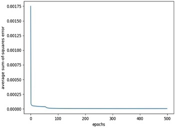
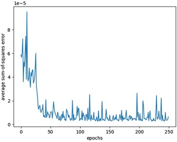
In addition to selecting the number of layers and nodes of the DNN, appropriate hyper-parameters (batch size and epochs) need to be selected during the training of the DNN. When the batch size is selected as 64, and epochs is selected as 500, the curve of average sum-of-squares error during the training set and the test set training histories is shown in Figs. 4 and 5.
Training histories of the training set error.

Training histories of the test set error.

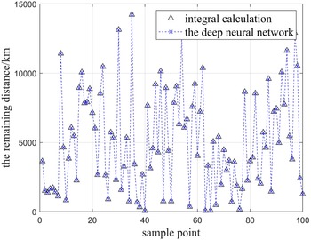
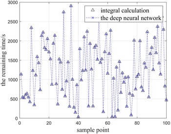
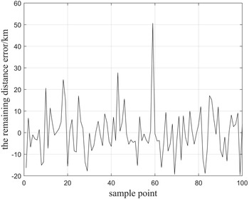
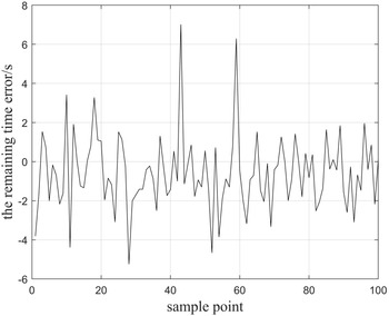
To verify the accuracy of the trained DNN, 100 sample points are randomly selected and put into the trained network to obtain the remaining distance and remaining time. The study compared the remaining distance and remaining time obtained by the DNN with the remaining distance and remaining time obtained by integration, as shown in Figs. 6 and 7. Figures 8 and 9 are the absolute error curves of the remaining distance and remaining time fit by the DNN respectively. In Fig. 8, the maximum error of the remaining flight distance is 52 kilometers. In Fig. 9, the maximum error of the remaining flight time is 7.2 seconds. The error is within the allowed range for the HGV with a range of several thousand kilometers and a flying duration of several thousand seconds.
Fitting curve of the remaining distance.

Fitting curve of the remaining time.

The remaining distance error of DNN.

The remaining time error of DNN.

After the DNN is trained, the prediction can be replaced by the DNN, and the correction uses the binary Newton iteration method to solve the two parameters of the bank angle profile. In each guidance cycle, the two parameters of the bank angle profile are corrected based on the constraints of distance and time.
 \begin{align} \left\{ {\begin{array}{*{20}{c}}{{s_{NN}} = {s_f}}\\[5pt] {{t_{NN}} = {t_d}}\end{array}} \right.\end{align}
where
 ${s_{NN}}$
is the remaining distance fitted by the DNN,
 ${s_f}$
is the ideal remaining distance, it can be obtained from the current longitude and latitude and the terminal longitude and latitude;
 ${t_{NN}}$
is the remaining time fitted by the DNN,
 ${t_d}$
is the ideal remaining distance, it can be obtained by subtracting the elapsed time from the total time. Based on Equation (1),
 ${s_f}$
and
 ${t_d}$
can be obtained from the current state
 $x = [\begin{array}{*{20}{l}}r & \lambda & \phi & V & \theta & \psi & t\end{array}]$
of the vehicle:
 \begin{align} {s_f} = \arccos \!(\sin \phi \sin {\phi _f} + \cos \phi \cos {\phi _f}\cos\!({\theta _f} - \theta ))\end{align}
 \begin{align} {t_d} = {t_{co}} - t\end{align}
In Equations (21)–(22),
 ${s_f}$
and
 ${t_d}$
are known variables,
 ${s_{NN}}$
and
 ${t_{NN}}$
are adjusted by the input of the DNN, the input of the DNN can be changed by adjusting the two adjustment parameters of the bank angle profile. Therefore, Equation (20) can be transformed into a two-variable nonlinear system of equations:
 \begin{align} \left\{ {\begin{array}{*{20}{l}}{Q({\sigma _{mid}},{\sigma _f}) = {s_{NN}} - {s_f} = 0}\\[5pt] {P({\sigma _{mid}},{\sigma _f}) = {t_{NN}} - {t_d} = 0}\end{array}} \right.\end{align}
Equation (23) can be solved by using the Newton iteration method of finding the roots of the binary nonlinear equation system.
 \begin{align} \left\{ {\begin{array}{*{20}{l}}{{\sigma _{mid,k + 1}} = {\sigma _{mid,k}} + \dfrac{{Q{{P'}_{\!\!{\sigma _f}}} - P{{Q'}_{\!\!{\sigma _f}}}}}{{{{P'}_{\!\!{\sigma _{mid}}}}{{Q'}_{\!\!{\sigma _f}}} - {{Q'}_{\!\!{\sigma _{mid}}}}{{P'}_{\!\!{\sigma _f}}}}}}\\[14pt] {{\sigma _{f,k + 1}} = {\sigma _{f,k}} + \dfrac{{P{{Q'}_{\!\!{\sigma _{mid}}}} - Q{{P'}_{\!\!{\sigma _{mid}}}}}}{{{{P'}_{\!\!{\sigma _{mid}}}}{{Q'}_{\!\!{\sigma _f}}} - {{Q'}_{\!\!{\sigma _{mid}}}}{{P'}_{\!\!{\sigma _f}}}}}}\end{array}} \right.\end{align}
whereafter the initial values of
 ${\sigma _{mid}}$
and
 ${\sigma _f}$
are determined,
 ${\sigma _{mid}}$
and
 ${\sigma _f}$
of the next iteration are obtained from Equation (24) The initial values of
 ${\sigma _{mid}}$
and
 ${\sigma _f}$
of the next guidance cycle are the final values of
 ${\sigma _{mid}}$
and
 ${\sigma _f}$
of the previous guidance cycle.
 ${Q'_{\!\!{\sigma _{mid}}}}$
,
 ${Q'_{{\!\!\sigma _f}}}$
,
 ${P'_{{\!\!\sigma _{mid}}}}$
and
 ${P'_{{\!\!\sigma _f}}}$
are the partial derivatives of Equation (23) concerning two parameters
 $(\sigma {}_{mid},{\sigma _f})$
, they can be obtained by finite difference approximation, for instance
 \begin{align} {Q'}_{{\!\!\sigma _{mid}},k} = \frac{{Q({\sigma _{mid,k}} + \Delta ,{\sigma _{f,k}}) - Q({\sigma _{mid,k}},{\sigma _{f,k}})}}{\Delta }\end{align}
where
 $\Delta > 0$
is a small constant. According to Equations (24)–(25), the values of iterative
 ${\sigma _{mid,k}}$
and
 ${\sigma _{f,k}}(k = 1,2,3 \ldots )$
can be obtained. Substituting the values of
 ${\sigma _{mid,k}}$
and
 ${\sigma _{f,k}}$
into Equation (23), the DNN can quickly calculate the values of
 $Q({\sigma _{mid}},{\sigma _f})$
and
 $P({\sigma _{mid}},{\sigma _f})$
. When the values of
 $Q({\sigma _{mid}},{\sigma _f})$
and
 $P({\sigma _{mid}},{\sigma _f})$
satisfy the following Equation (26), at this time, the final values of the two adjustment parameters of the bank angle profile in one guidance period can be obtained:
 \begin{align} \left\{ {\begin{array}{*{20}{c}}{Q({\sigma _{mid,k}},{\sigma _{f,k}}) < {\varepsilon _1}}\\[5pt] {P({\sigma _{mid,k}},{\sigma _{f,k}}) < {\varepsilon _2}}\end{array}} \right.\end{align}
where
 ${\varepsilon _1}$
is the small error value of the distance,
 ${\varepsilon _2}$
is the small error value of the time.
3.4 Determining the sign of the bank angle based on the section heading angle corridor
This paper uses the heading angle corridor method to determine the sign of the bank angle for lateral guidance.
 \begin{align} {\psi _{Los}} = \arctan \frac{{\sin\!({\lambda _f} - \lambda )}}{{\cos \phi \cos {\phi _f} - \sin \phi \cos\!({\lambda _f} - \lambda )}}\end{align}
where
 ${\psi _{Los}}$
is the line angle of sight from the current position of the vehicle to the target,
 $\lambda $
and
 $\phi $
are the current latitude and longitude, they can be obtained from the current state
 $x = [\begin{array}{*{20}{l}}r & \lambda & \phi & V & \theta & \psi & t\end{array}]$
. Therefore, the current heading angle error is that:
 \begin{align} \Delta \psi = \psi - {\psi _{los}}\end{align}
When the heading angle error exceeds the preset error corridor, the sign of the bank angle should be changed; otherwise, when the heading angle does not exceed the error corridor, the sign of the bank angle remains unchanged. In other words:
 \begin{align} sign({\sigma _n}) = \left\{ {\begin{array}{*{20}{l}}{ - 1,\Delta \psi > \delta \psi }\\[5pt] {1,\Delta \psi < - \delta \psi }\\[5pt] {sign({\sigma _{n - 1}}), - \delta \psi \le \Delta \psi \le \delta \psi }\end{array}} \right.\end{align}
where
 ${\sigma _n}$
is the current bank angle,
 ${\sigma _{n{\rm{ - }}1}}$
is the bank angle of the previous moment,
 $\delta \psi $
is the preset heading angle error threshold. To control the accuracy of the landing point, this paper adopts a segmented heading angle error threshold, the larger heading angle error threshold
 $\delta {\psi _{\max }}$
is adopted in the initial phase of flight, and the smaller heading angle error threshold
 $\delta {\psi _{\min }}$
is adopted in the phase of approaching the terminal energy, as Fig. 10 shows.
The segmented heading angle error threshold.

3.5 Aerodynamic parameter identification
The performance of the entry vehicle is reduced due to insufficient accuracy in the ground wind tunnel test or the pre-estimated aerodynamic characteristics of the aerodynamic calculation and the actual flight. In the design process of the DNN in this paper, the influence of the aerodynamic parameter disturbance
 $(\begin{array}{*{20}{c}}{{k_{cl}}} & {{k_{cd}}}\end{array})$
has been taken into consideration and used as the input of the DNN. In order to obtain
 ${k_{cl}}$
and
 ${k_{cd}}$
in the guidance process, EKF is used for online aerodynamic identification.
The identification quantity is selected as the actual lift coefficient
 ${C_L}$
and drag coefficient
 ${C_D}$
, and it is considered that the change of lift coefficient and drag coefficient conforms to the Gauss-Markov process. The selected state quantity is
 $\vec X = [\begin{array}{*{20}{l}}H & V & \theta & {{C_L}} & {{C_D}}\end{array}]$
, the state transition model can be obtained according to Equations (1)–(2), as shown in the Equation (30)
 \begin{align} \vec{\dot{X}} = f(\vec X) + {\vec \omega _k} = \left\{ {\begin{array}{*{20}{l}}{\dfrac{{d\hat H}}{{dt}} = \hat V\sin \hat \theta + {\omega _H}}\\[12pt] {\dfrac{{d\hat V}}{{dt}} = - \dfrac{{{e^{ - \frac{{(r - {\mathop{\rm Re}\nolimits} )}}{{{h_s}}}}}S{{\hat V}^2}{\rho _0}{C_D}}}{{2m}} - g\sin \hat \theta + {\omega _V}}\\[12pt] {\dfrac{{d\hat \theta }}{{dt}} = - \dfrac{{{e^{ - \frac{{(r - {\mathop{\rm Re}\nolimits} )}}{{{h_s}}}}}S{{\hat V}^2}{\rho _0}{C_L}\cos \sigma }}{{2m\hat V}} - \dfrac{{g\sin \hat \theta }}{{\hat V}} + \dfrac{{V\cos \hat \theta }}{{\hat r}} + {\omega _\theta }}\\[12pt] {\dfrac{{d{C_L}}}{{dt}} = {\omega _L}}\\[12pt] {\dfrac{{d{C_D}}}{{dt}} = {\omega _D}}\end{array}} \right.\end{align}
where
 $\vec \omega = \left[ {\begin{array}{*{20}{l}}{{\omega _H}} & {{\omega _V}} & {{\omega _\theta }} & {{\omega _L}} & {{\omega _D}}\!\end{array}} \right]$
is the process noise of each state quantity.
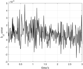
 ${{\bf{k}}_{{\bf{cl}}}}$
aerodynamic identification error.

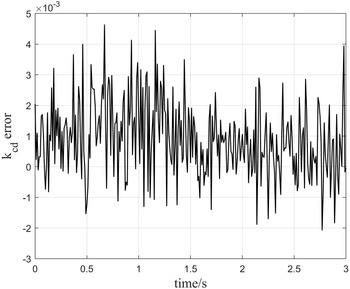
 ${{\bf{k}}_{{\bf{cd}}}}$
aerodynamic identification error.

The navigation system measures the relative velocity vector
 $\tilde V$
and the non-gravitational acceleration vector
 ${a_{Nav}}$
, obtain the lift acceleration
 $\tilde L$
and drag acceleration
 $\tilde D$
, consider the real-time measurable height
 $\tilde H$
, [Reference Shen and Lu30] and establish the observation model as
 \begin{align} \vec y = f(\vec X) + {\vec v_k} = \left\{ {\begin{array}{*{20}{c}}{{{\tilde L}_c} = \tilde L + {v_L}}\\[5pt] {{{\tilde D}_c} = \tilde D + {v_D}}\\[5pt] {{{\tilde H}_c} = \tilde H + {v_H}}\\[5pt] {{{\tilde V}_c} = \tilde V + {v_V}}\end{array}} \right.\end{align}
where
 ${\tilde L_c}$
,
 ${\tilde D_c}$
,
 ${\tilde H_c}$
,
 ${\tilde V_c}$
are the measured values of lift acceleration, drag acceleration, altitude, and velocity respectively;
 ${\vec v_k} = [\begin{array}{*{20}{c}}{{v_L}} & {{v_D}} & {{v_H}} & {{v_V}}\end{array}]$
is the observation noise.
According to literature [Reference Evensen31], an EKF is created and utilised to estimate the real lift coefficient and drag coefficient. The aerodynamic parameter disturbance coefficient is obtained by the ratio of the actual value of the lift coefficient
 ${C_L}$
and the actual value of the drag coefficient
 ${C_D}$
obtained by the identification of the nominal value of the lift coefficient
 ${C_{L0}}$
and the nominal value of the drag coefficient
 ${C_{D0}}$
obtained according to the literature [Reference Jorris and Cobb23]. In other words:
 \begin{align} \left\{ {\begin{array}{*{20}{c}}{{k_{cl}} = \dfrac{{{C_L}}}{{{C_{L0}}}}}\\[10pt] {{k_{cd}} = \dfrac{{{C_D}}}{{{C_{D0}}}}}\end{array}} \right.\end{align}
The fluctuation range of the aerodynamic parameter correction coefficient is
 $[\!-\!20\% ,20\% ]$
, and the sine function
 $1{\rm{ + 0}}{\rm{.2sin}}\left(\frac{{2\pi }}{3}{\rm{t}}\right)$
used to characterise, error curve is obtained by comparing
 ${k_{cl}}$
and
 ${k_{cd}}$
obtained by aerodynamic identification with the true value is shown in Fig. 11 and Fig. 12. It can be seen from Figs. 11 and 12 that EKF can accurately estimate
 ${k_{cl}}$
and
 ${k_{cd}}$
.
Time-coordination entry missions

Altitude-velocity profile curve in nominal condition.

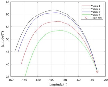
Ground track in nominal condition.

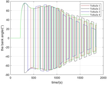
Bank angle profiles in nominal condition.

4.0 Simulation
The CAV-H vehicle selected for the entry vehicle model has a mass of 907kg and a reference area of
 $0.4838{m^2}$
[Reference Phillips32]. The heating rate, aerodynamic overload, and dynamic pressure constraints are set as
 ${\dot Q_{\max }} = 1000kw/{m^2}$
,
 ${n_{\max }} = 3{g_0}$
,
 ${q_{\max }} = 150kpa$
respectively. In the angle-of-attack profile,
 ${\alpha _m}{\rm{ = 2}}{{\rm{0}}^ \circ }$
,
 ${\alpha _{L/{D_{\max }}}} = {10^\circ }$
. In the predictor-corrector, the iteration cut-off errors are
 ${\varepsilon _1} = 5km$
and
 ${\varepsilon _2} = 5s$
. The initial values of the designed bank angle profiles are set as
 ${\sigma _0} = {60^ \circ }$
,
 ${\sigma _{mid}} = {70^ \circ }$
,
 ${\sigma _0} = {35^ \circ }$
. The heading angle error threshold is set as
 $\delta {\psi _{\max }} = {10^ \circ }$
,
 $\delta {\psi _{\max }} = {5^ \circ }$
. In addition, the terminal cut-off condition is selected as the vehicle speed. In DNN, the batch size is set as 64, and the epochs are set as 500.
In the simulations, unless noted otherwise all the following numerical results are generated using a computer with AMD Ryzen 7 4800H processor (2.90 GHz, 8 cores, 16 threads), 16.0 GB memory, and a Windows operation system. The DNN training environment is PyCharm Community Edition, and the development language is Python, and the training framework is selected as tensorflow2.0.
4.1 Multi-task simulation under nominal conditions
Under nominal conditions, for the time-coordination entry mission based on deep learning of the hypersonic gliding vehicle, the four different initial positions of the vehicles in Table 4 are selected for simulation to verify the effectiveness of the algorithm.
The terminal status of each flight mission is shown in Table 4. Figures 13, 14 and 15 are numerical simulation images of each flight mission under nominal conditions. Figure 13 shows the high-velocity profile curve for different missions, the four curves all satisfy the Quasi-Equilibrium Guide Condition and path constraints. Figure 14 displays the ground track in nominal condition. Figure 15 is the bank angle profile in nominal condition, the terminal bank angle is gradually reduced to meet the time constraint. Table 5 shows the terminal errors based on deep learning. It can be seen that the terminal errors of each mission meet the error requirements. Table 6 compares the traditional integration algorithm with time-coordination algorithm based on deep learning in this paper for each guidance cycle. It should be noted that the algorithm proposed in this paper is only 2% of the loss time of the traditional integration algorithm.
Terminal errors in nominal conditions

Algorithm running time comparison

The perturbation settings in guidance simulation

Altitude-velocity profiles curve for mission 4 under disturbance conditions.

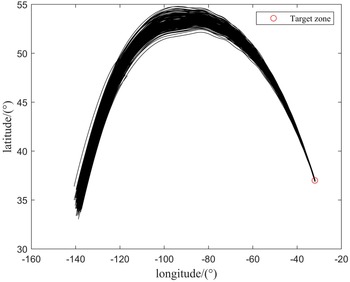
Ground tracks for mission 4 under disturbance conditions.

Bank angle profiles for mission 4 under disturbance conditions.

Falling point dispersion for mission 4 under disturbance conditions.

Terminal altitude-velocity error dispersion for mission 4 under disturbance conditions.

Histogram of terminal flight time errors for mission 4 under disturbance conditions.

Therefore, from the above simulation results, it can be seen that the time-coordination guidance algorithm based on deep learning proposed in this paper can meet the needs of multi-HGV entry coordination flight, and the addition of a DNN greatly improves the real-time performance of this algorithm.
4.2 Multi-task simulation under disturbance conditions
The trained DNN itself has a certain amount of anti-interference ability; in this paper, the EKF is used to identify the aerodynamic parameters online and use them as the input for the DNN, which can greatly improve the robustness of the time-coordination guidance algorithm. To verify the robustness and accuracy of the time-coordination guidance algorithm based on deep learning, 200-run Monte Carlo simulations are conducted on mission 4 in Table 4. The initial state deviations and parameter deviations in Table 7 conform to the normal distribution.
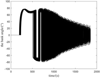
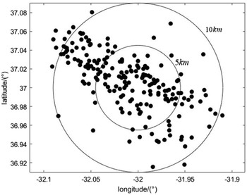
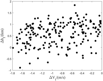
The numerical simulation results under disturbance conditions are shown in Figs. 16, 17, 18, 19, 20 and 21. Figure 16 displays the high-velocity profile curve for mission 4 under disturbance conditions, the curve shows that under disturbance conditions, the trajectory can still satisfy the path constraints and Quasi-Equilibrium Guide Condition. Figure 17 shows the ground tracks for mission 4 under disturbance conditions. Figure 18 displays the bank angle profiles for mission 4 under disturbance conditions, it can be concluded that the bank angle can still fluctuate within a reasonable range under disturbance conditions. Figure 19 is the falling point dispersion for mission 4 under disturbance conditions, it can be seen that the terminal drop points are scattered along the flight direction, most of the landing points are within 5km, and the rest are within 10km, which meets the needs of entry guidance. Figure 20 shows the terminal altitude-velocity error dispersion for mission 4 under disturbance conditions. From Fig. 20, it is indicated that the terminal velocity error is within 1.8m/s, and the terminal altitude error is within 2km. Figure 21 shows the histogram of terminal flight time errors for mission 4 under disturbance conditions, it indicates that the flight time error is within 4s.
Thus, it can be established from the simulation results that the time-coordination guidance algorithm based on deep learning proposed in this paper still has good guidance accuracy under the condition of initial state disturbance and parameter disturbance, proving the robustness of the algorithm in this paper.
5.0 Conclusion
This paper presented a guiding system for multi-hypersonic gliding vehicles that utilised DNN for guidance. A dual-parameter bank angle profile was used to suit the requirements of time coordination. To address the real-time needs of the HGV guiding algorithm, this research developed a range of DNN architectures and used error comparison to pick the network structure that was most suited for the situation at hand. A vehicle trajectory database was created and utilised to train the DNN structure that had been established. To enhance the algorithm’s resilience, the EKF was employed to detect the disturbance coefficient of aerodynamic parameters online and utilised it as one of DNN the inputs to enhance the algorithm’s anti-interference capacity. The simulation results using CAV-H vehicles demonstrated that the developed DNN structure was capable of meeting the temporal coordination requirements of several vehicles. Assuming the guiding accuracy matches the criteria, this method exhibited high resilience, excellent real-time performance, and the potential for online application.
Conflict of interest statement
The authors declare that there is no conflict of interest in this work.