1. INTRODUCTION
Conceptual design is an early design phase that involves generation of solution concepts to satisfy functional requirements of a design problem (Chakrabarti & Bligh, Reference Chakrabarti and Bligh1994); this involves both identification and satisfaction of requirements (Nidamarthi et al., Reference Nidamarthi, Chakrabarti and Bligh1997). Although later stages of design are also important and often well supported (e.g., Taguchi, Reference Taguchi1986; Boothroyd & Dewhurst, Reference Boothroyd and Dewhurst1987; Chakrabarti et al., Reference Chakrabarti, Bligh and Holden1992; Pahl & Beitz, Reference Pahl and Beitz2008; Erlenspiel, Reference Ehrlenspiel, Kiewert and Lindemann2007), earlier stages of design, especially conceptual design, are widely regarded as crucially important, because a high percentage of the product cost is committed during this stage whereas cost incurred is relatively low (Berliner & Brimson, Reference Berliner and Brimson1988; Flint & Gaylor, Reference Flint and Gaylor1995).
A thorough exploration of solution space enhances the likelihood of creating designs of higher quality (Langdon & Chakrabarti, Reference Langdon and Chakrabarti1999). Therefore, exploring a large number of alternatives during conceptual design is important (Ullman, Reference Ullman1992; Blessing et al., Reference Blessing, Chakrabarti and Wallace1995; Pahl & Beitz, 1996).
However, conceptual design is difficult (Mabie & Reinholtz, Reference Mabie and Reinholtz1987; Ulrich & Seering, Reference Ulrich and Seering1989); it relies primarily on designers' intuition and experience to guide the process, and often not many design alternatives are explored (Adams, Reference Adams1986; Jansson & Smith, Reference Jansson and Smith1991; Chakrabarti & Bligh, Reference Chakrabarti and Bligh1994). Major reasons for this include the tendency to delimit a design problem too narrowly, awareness of and bias toward a limited set of ideas, and time constraint (Li, Reference Li1998).
Inspiration is useful for exploration and discovery of new solution spaces (Murakami & Nakajima, Reference Murakami and Nakajima1997), as indicated by, for example, the fact that using (e.g., biological) stimuli leads to generation of a large number of ideas (Kletke et al., Reference Kletke, Mackay, Barr and Jones2001; Sarkar & Chakrabarti, Reference Sarkar and Chakrabarti2008; Sarkar et al., Reference Sarkar, Phaneendra and Chakrabarti2008), that stimulus-rich creativity techniques positively influence creativity (MacCrimmon & Wagner, Reference MacCrimmon and Wagner1994; Watson, Reference Watson1989), or that structuring of meanings enhances search for stimuli (Georgiev et al., Reference Georgiev, Taura, Chakrabarti and Nagai2008).
Therefore, providing appropriate stimuli to help generate a wide variety of design alternatives during conceptual design is important in mechanical design. The aim of the research reported in this paper is to develop a system that can synthesize a range of design alternatives during mechanical conceptual design and provide these to designers as stimuli for creating new designs, thereby helping designers explore a wider variety of solution alternatives.
This paper outlines the theory behind a computational tool called FuncSION that uses automated, combinatorial synthesis with a set of building blocks to generate a variety of designs and provides these to designers for exploration; the paper then reports results from evaluation of FuncSION for the effectiveness of using its outputs as stimuli for ideation in mechanical design. It is part of a long-term project for developing a decision-support framework (Chakrabarti et al., Reference Chakrabarti, Bligh and Holden1992) for efficiently aiding design creativity (Chakrabarti, Reference Chakrabarti2001, Reference Chakrabarti2006; Chakrabarti & Singh, Reference Chakrabarti and Singh2007). Although some aspects of FuncSION were reported earlier (Chakrabarti & Bligh, Reference Chakrabarti and Bligh1994, Reference Chakrabarti and Bligh1996a, Reference Chakrabarti and Bligh1996b, Reference Chakrabarti and Bligh1996c; Chakrabarti & Tang, Reference Chakrabarti and Tang1996; Liu et al., Reference Liu, Chakrabarti, Bligh and Gero2000), a consolidated exposition of all its aspects, implementation of its theory for physical synthesis, embodiment of FuncSION as a design tool with a graphical user interface (GUI), and comparative evaluation of FuncSION in aiding ideation in designers have never been reported before.
Fluency (the number of ideas generated during design) is an important factor influencing variety (how different the ideas explored during design are; Renzulli et al., Reference Renzulli, Owen and Callahan1974; Torrance, Reference Torrance and Passow1979): the larger the fluency, the more the variety and novelty of the ideas (Srinivasan & Chakrabarti, Reference Srinivasan and Chakrabarti2010), where novelty is a major indicator of creativity (Young, Reference Young1987; Kletke et al., Reference Kletke, Mackay, Barr and Jones2001; Sarkar & Chakrabarti, Reference Sarkar and Chakrabarti2011). Therefore, fluency is used as the criterion for evaluation of FuncSION.
2. LITERATURE REVIEW
Ulrich and Seering (Reference Ulrich and Seering1989) proposed an approach to automated synthesis of schematic descriptions of mechanical designs for single-input single-output dynamic systems. Design problems are specified by input–output (I/O) quantity and a desired relationship between I/O. Schematic descriptions are graphs of functional building blocks; a building block consists of an effort and a flow variable. Schematic synthesis has three steps: generate candidate schematic descriptions from which all possible solutions can be obtained through augmentations to one of these descriptions, derive and classify the behavior of these candidate descriptions, and modify the candidates to meet the specifications. However, the approach does not address spatial aspects of designs, an essential feature of mechanical design.
Prabhu and Taylor (Reference Prabhu and Taylor1989) used a set of functional primitives as building blocks with orientations, magnitudes, and positions as characteristics, and proposed to generate functional networks of these primitives as solutions to multiple-input multiple-output problems. On the basis of a formal mathematical representation, they proposed several theorems on the properties of generic algorithms for building systems using a chosen spanning set of functional primitives, maximum and minimum bounds on their complexity, and so forth. However, the approach does not address spatial aspects of designs and is not reported to have been implemented.
Li et al. (Reference Li, Tan and Chan1996) proposed a qualitative approach to generating a design for a functional specification, using a library of mechanical devices with known function and behavior. A mechanical device is represented using I/O, the relationship between I/O, and control. When a functional specification is partially satisfied by a design with a maximum score, new designs are generated by applying transformation rules. The synthesis process continues until all requirements are satisfied. This work evolved further (Li et al., Reference Li, Chan and Tan1999) into a method where kinematic devices are synthesized using configuration space. Function and behavior of a kinematic pair are represented using effort, motion, and motion constraints. A database of possible behaviors of kinematic pairs is developed, in which change in configuration and the corresponding function this represents are stored together. A heuristic search algorithm is used to retrieve solutions from the database. Although this approach addresses some spatial aspects of I/O in an abstract manner, it cannot generate spatially distinct configurations. Further, synthesis stops once a solution is found, and hence does not support ideation with a variety of designs as stimuli.
Kota and Chiou (Reference Kota and Chiou1999) developed an approach to represent building blocks at different levels of abstraction, generate alternative conceptual designs, and facilitate rapid simulation of design concepts. They compiled a database of functional building blocks with rotational, translational, and helical motion, and proposed a matrix-based approach to synthesize mechanisms for function generation using these building blocks. The desired motion transformation matrix (MTM) for a design task is decomposed into a product of MTMs by transformation rules; the decomposed matrices are matched against the MTMs of existing building blocks to identify possible combinations of building blocks to fulfill the design task. This work, however, does not address spatial aspects of designs.
Yan and Ou (Reference Yan and Ou2005) proposed a method for synthesizing mechanical devices by combining configuration spaces of kinematic building blocks; the building blocks are characterized by rotation or translation as I/O motions. Three types of combination are used: serial, parallel, and serial and parallel. The synthesis procedure finds possible and feasible serial and/or parallel configurations of given building blocks and power sources using graph theory. Once again, the work does not address spatial aspects.
The name of the compositional synthesis tool FuncSION (Chakrabarti, Reference Chakrabarti1991; Liu et al., Reference Liu, Chakrabarti, Bligh and Gero2000) stands for Functional Synthesizer of Input–Output Networks. It automatically synthesizes solution concepts for mechanical devices, addressing spatial aspects, as detailed in Section 3.
3. FuncSION
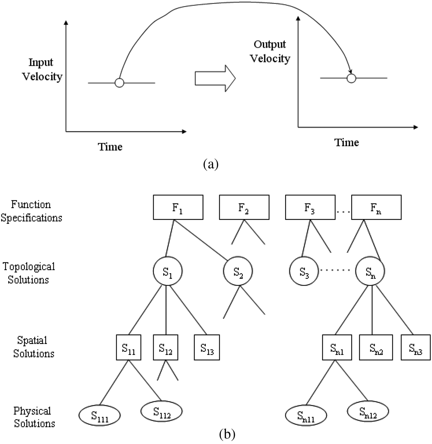
In mechanical design, a major functional requirement is to transmit and transform forces and motion. This can be expressed as a transformation between a set of I/O characteristics (Chakrabarti & Bligh, Reference Chakrabarti and Bligh1994). Each characteristic may be required over a particular period of time during the functioning of the device. The transformation at an instant of time between the I/O characteristics is termed instantaneous transformation (Chakrabarti & Bligh, Reference Chakrabarti and Bligh1994; Fig. 1a). An ordered set of such transformations can be used to express the overall functional requirements of a transmission design problem. In this approach, a solution concept is an abstract description of a system of functional building blocks that can satisfy given functional requirements. For instance, a solution concept for transmitting a force from one point to another on the same plane but in a different direction and position could constitute a rack that takes the input force to rotate a pinion that moves another rack to provide the required output motion (Chakrabarti & Bligh, Reference Chakrabarti and Bligh1994).
The methodology of FuncSION.

The instantaneous transformation of a given system can be computed using information about its constituent building blocks, connections, and their rules of combination. FuncSION can synthesize, using a database of functional building blocks, an exhaustive set of solution concepts to satisfy functional requirements of a design problem specified using its required instantaneous transformation (Chakrabarti & Bligh, Reference Chakrabarti and Bligh1994).
In FuncSION, a design problem is represented as a transformation between a set of instantaneous I/O vectors, each of which has the following characteristics: kind (the type of I/O, e.g., force or toque), orientation (spatial axis along which an I/O is oriented), sense (sense of the I/O along the orientation), position (spatial coordinates), and magnitude (Chakrabarti & Bligh, Reference Chakrabarti and Bligh1994). FuncSION allows users to select the functional building blocks to be used in the synthesis, where each building block can transform an input vector of specified characteristics into an output vector of specified characteristics (Chakrabarti & Bligh, Reference Chakrabarti and Bligh1996a). In FuncSION, synthesis of a solution concept is supported in a four-step process, leading to a tree of solutions at four levels of abstraction (Fig. 1b):
1. Function specification: The user specifies a design problem in terms of the kinds, orientations, senses, and positions of a set of inputs and outputs that define its functions.
2. Kind synthesis: This is an exhaustive search algorithm that synthesizes a set of topological solutions, that is, networks of causally connected, structurally feasible, functional building blocks, that transform the input-kind into the output-kind required for a design problem.
3. Spatial synthesis: It generates alternative spatial configurations for each topological solution using two procedures, orientation synthesis and sense synthesis, so that the concepts can satisfy the orientation and sense constraints of the design problem (Chakrabarti & Bligh, Reference Chakrabarti and Bligh1996a, Reference Chakrabarti and Bligh1996b).
4. Physical synthesis: It generates alternative embodiments for each spatial solution (Liu, Reference Liu2000).
3.1. Knowledge representation for functional building blocks
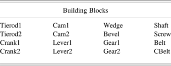
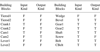
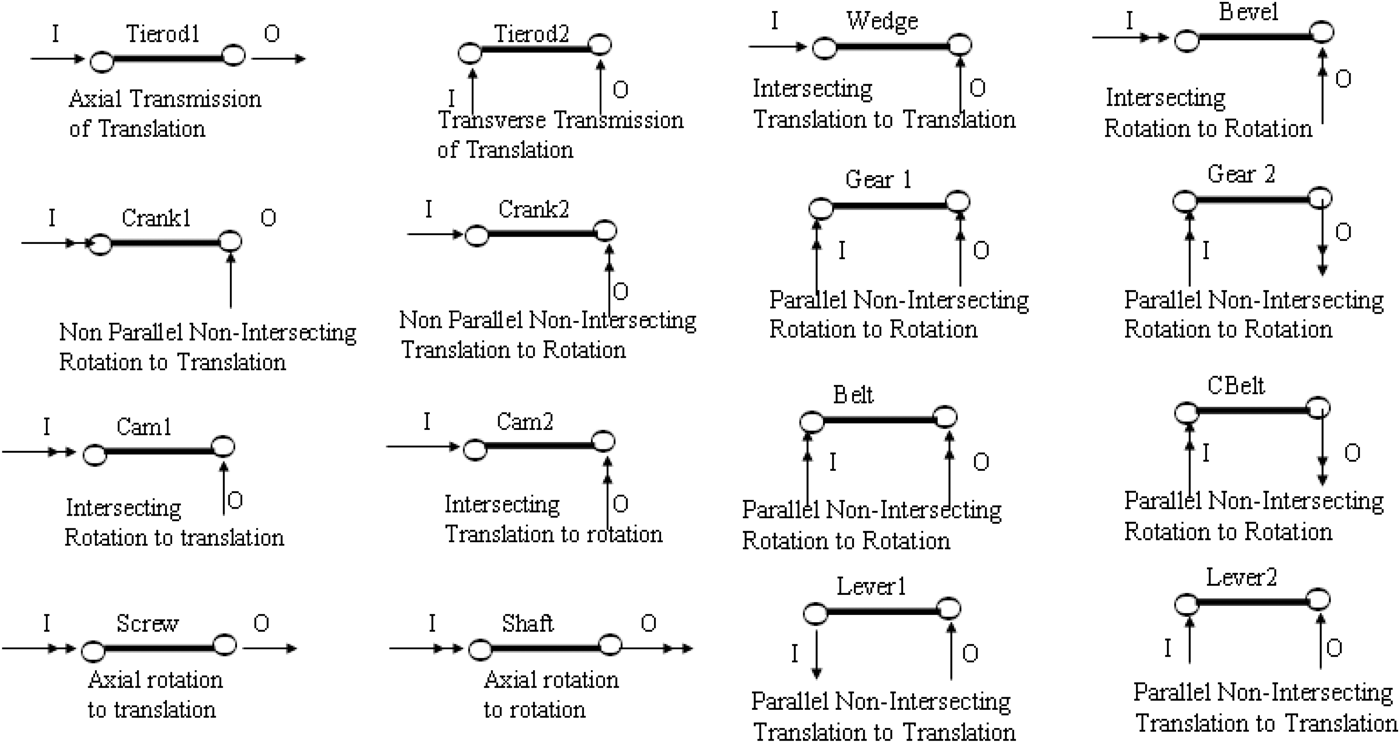
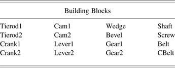
At each abstraction level from 2 to 4 above in FuncSION, a solution is formed by combining a set of common elements called building blocks, which have been extracted by analyzing existing designs and classified into three levels of abstraction: topological, spatial, and physical. The building blocks in FuncSION are enlisted in Table 1, and their representations at the abstraction levels are shown in Table 2.
Building blocks used in functional synthesis
Building blocks at topological level
Note: T, Torque; F, force.
3.1.1. Knowledge representation at the topological level
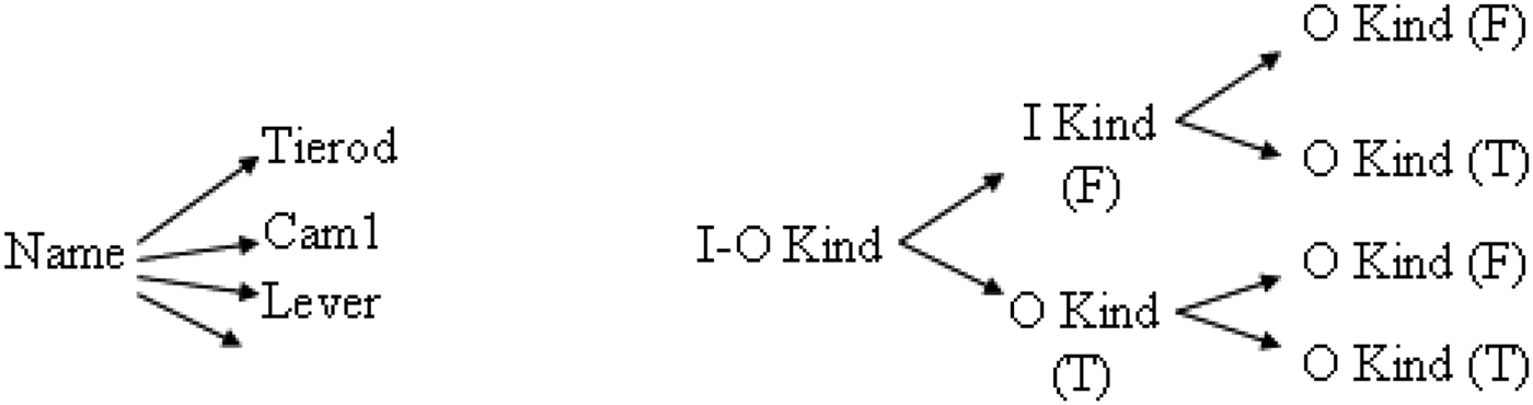
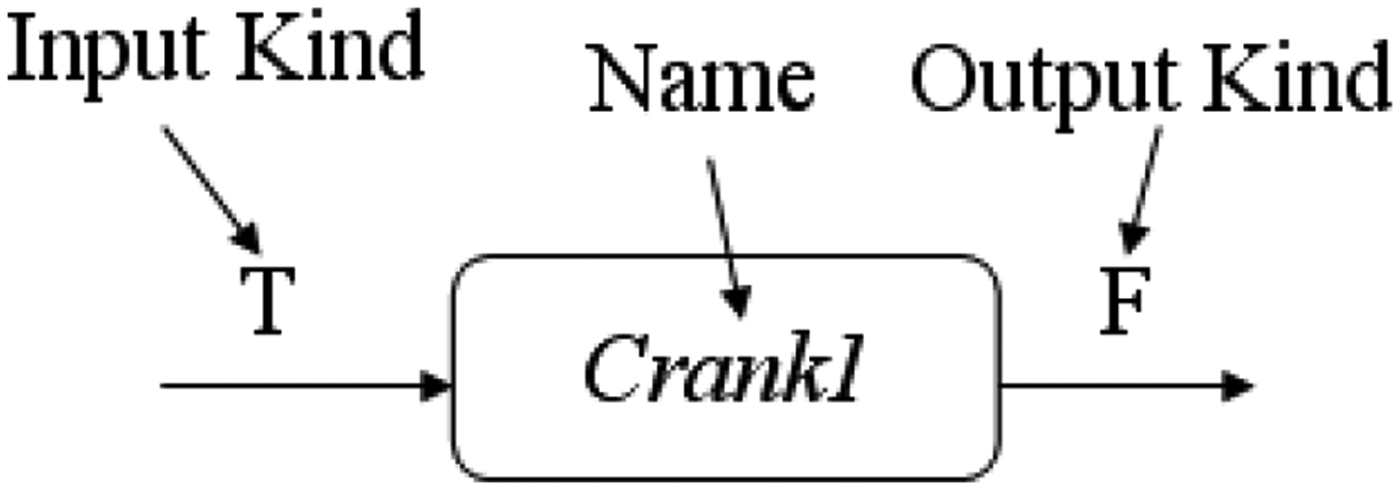
Building blocks at the topological level are described using attributes (Fig. 2): name, input-kind, and output-kind (Chakrabarti & Bligh, Reference Chakrabarti and Bligh1994). Name describes the name of the building block. Input-kind (or output-kind) describes the kind of input used (or output provided) by the building block. There are two kinds: force and torque. For example, building block Crank1 is used to transform an input-kind, torque, to an output-kind, force (Fig. 3).
Attributes of topological building blocks (Liu, Reference Liu2000).
Structure of a building block (Liu, Reference Liu2000).
3.1.2. Knowledge representation at the spatial level
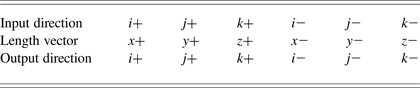
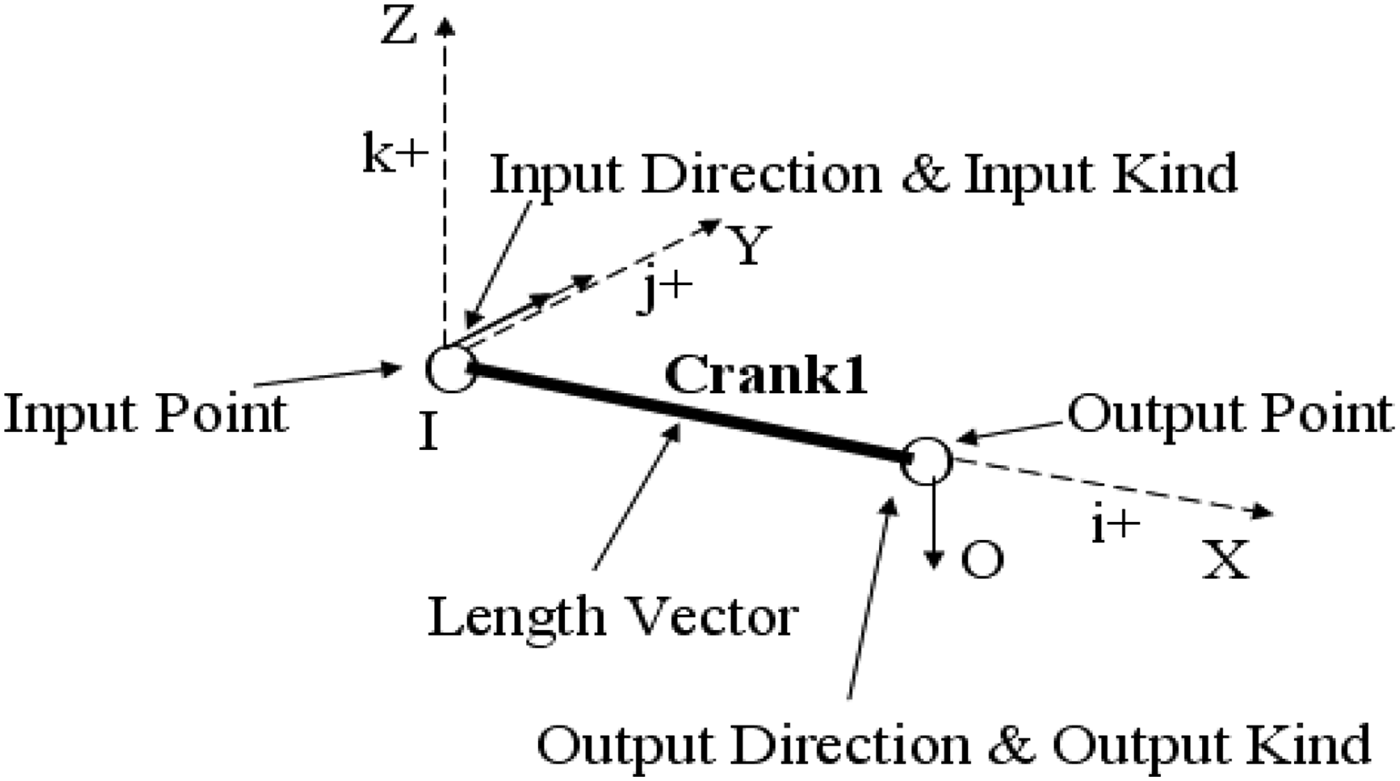
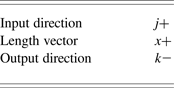
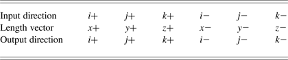
Building blocks at the spatial level are described by attributes: input direction (i.e., orientation and sense), length vector, and output direction (Chakrabarti & Bligh, Reference Chakrabarti and Bligh1996a, Reference Chakrabarti and Bligh1996b). Input (or output) direction describes the input (or output) direction of each building block, which can be along i+, j+, k+, i–, j–, or k– (Table 3). Length vector describes the relative position, orientation, and sense between the I/O (Chakrabarti & Bligh, Reference Chakrabarti and Bligh1996a, Reference Chakrabarti and Bligh1996b). The length vector of a building block can be oriented along the x+, y+ z+, x–, y–, or z– axis.
Attributes for spatial building blocks
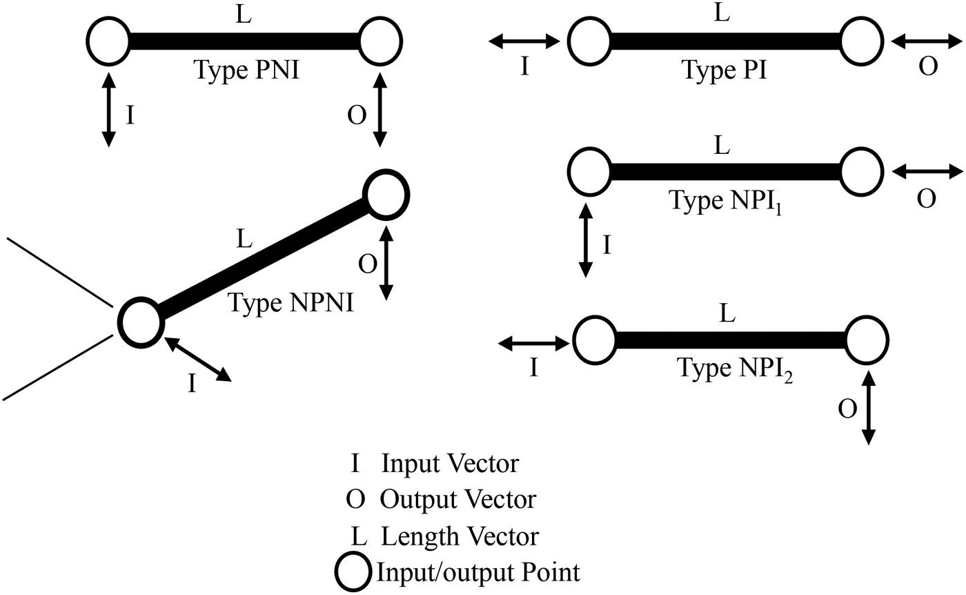
Input and output directions are related by one of these spatial relationships (Fig. 4): parallel and intersecting, parallel and nonintersecting, nonparallel and intersecting, and nonparallel and nonintersecting (Chakrabarti & Bligh, Reference Chakrabarti and Bligh1994). The various building blocks hold different spatial relationships (Fig. 5).
Possible spatial relationships between an input and output vector (Chakrabarti & Bligh, Reference Chakrabarti and Bligh1996c).
Building blocks at the spatial level.
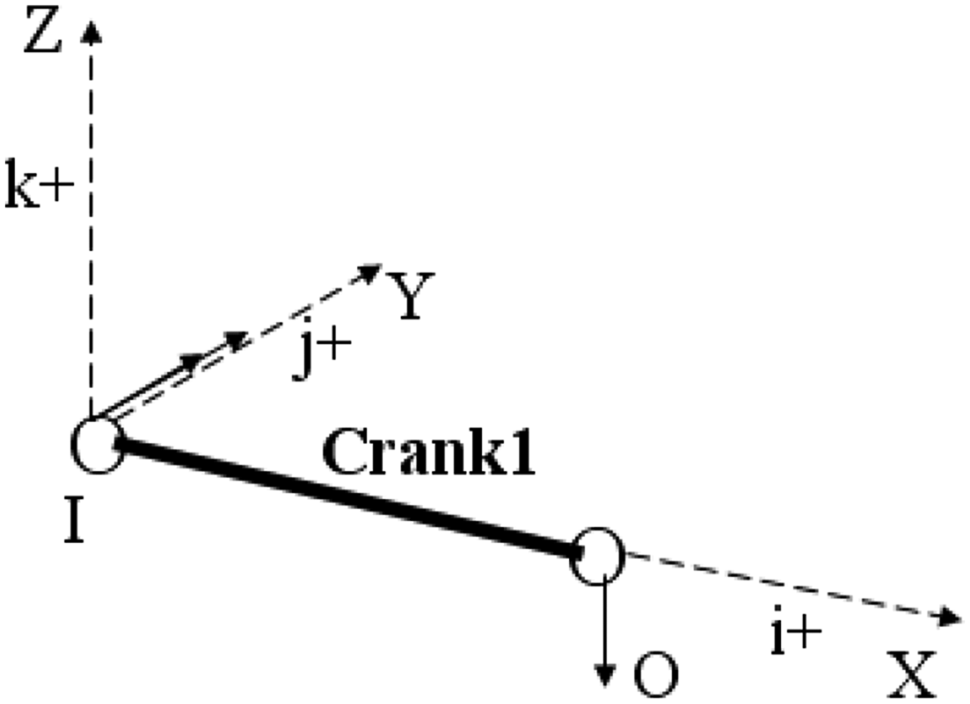
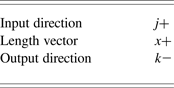
For instance, Crank1 building block (Fig. 6) has input direction along j+, length vector along x+, and output direction along k– (Table 4).
Structure of a spatial building block (Crank1; Liu, Reference Liu2000).
Spatial attributes of Crank1 building block
3.1.3. Knowledge representation at the physical level
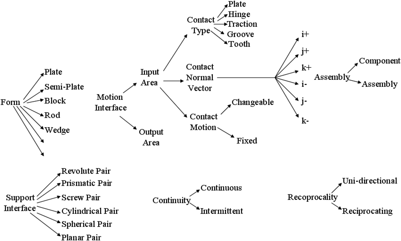
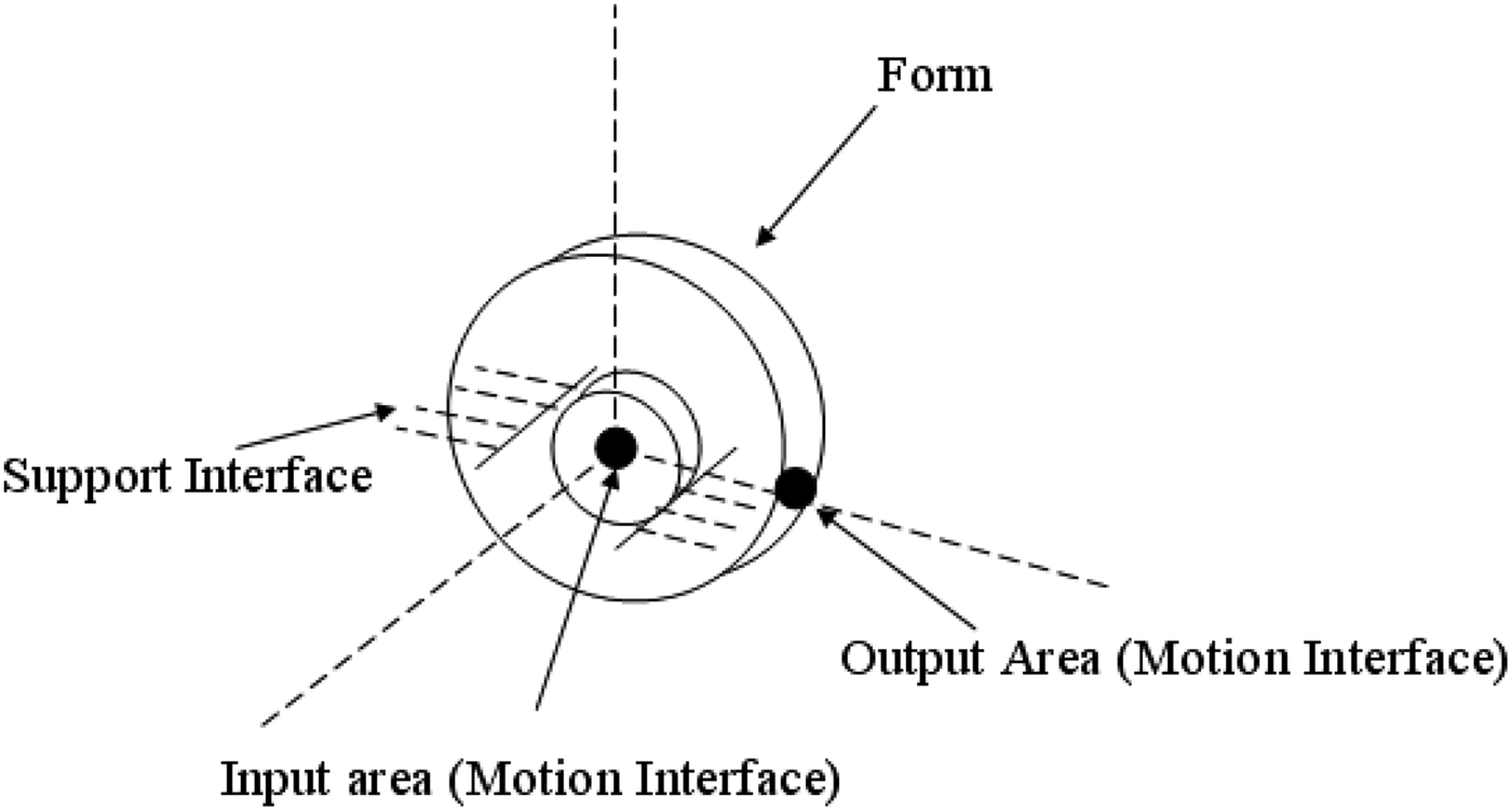
Building blocks at the physical level (Fig. 7) are described by three structural attributes, two kinematic behavioral attributes, and one assembly attribute (Liu et al., Reference Liu, Chakrabarti and Bligh1999; Liu, Reference Liu2000). Structural attributes describe generic geometry: form, support interface, and motion interface. Form describes the shape of the building block. Support interface provides spatial constraints, for example, revolute, prismatic, screw, cylindrical, spherical, or planar pairs. Motion interface provides an interface that carries energy and information from one object to another. Each motion interface contains an input area that connects to the output area of the previous building block and an output area that connects to the input area of the next building block. Each I/O area has three attributes: contact types, contact motion, and contact normal vector. Contact type describes the form of contact between two objects, for example, plane, traction, or tooth. Contact normal vector is the normal vector of the two contacting surfaces at the point of contact, and is described along the i+, j+, k+, i–, j–, or k– direction. Contact motion describes the degree of freedom of the connection between two successive building blocks, described as fixed or changeable with specified degrees of freedom, for example, a revolute pair. Kinematic behavior attributes describes the motion of the building blocks. The attributes are continuity: continuous or intermittent, and reciprocality: reciprocating or unidirectional. The assembly attribute describes whether a building block is a single component or an assembly. A component represents a single rigid body, for example, a shaft; an assembly has multiple components, for example, a cam and a follower (Liu et al., Reference Liu, Chakrabarti and Bligh1999; Liu, Reference Liu2000).
Attributes of physical building blocks (Liu, Reference Liu2000).
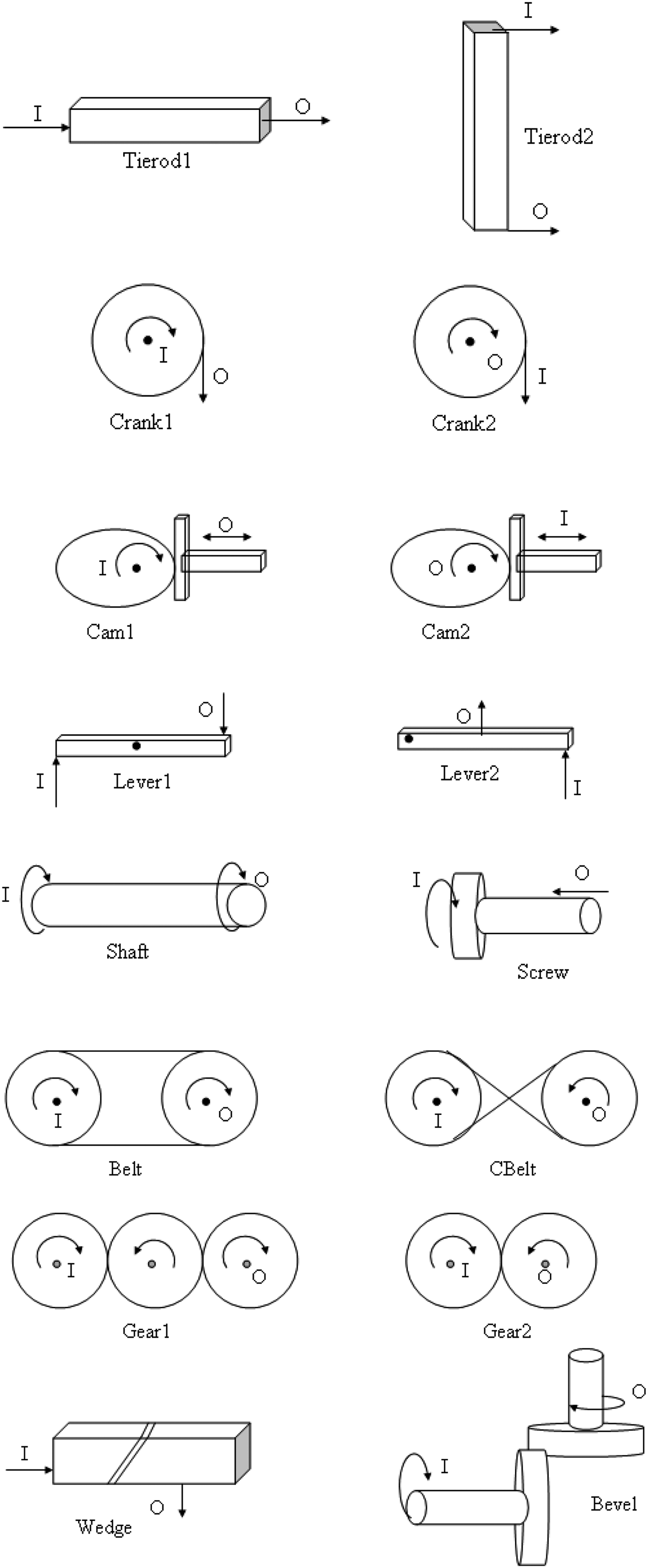
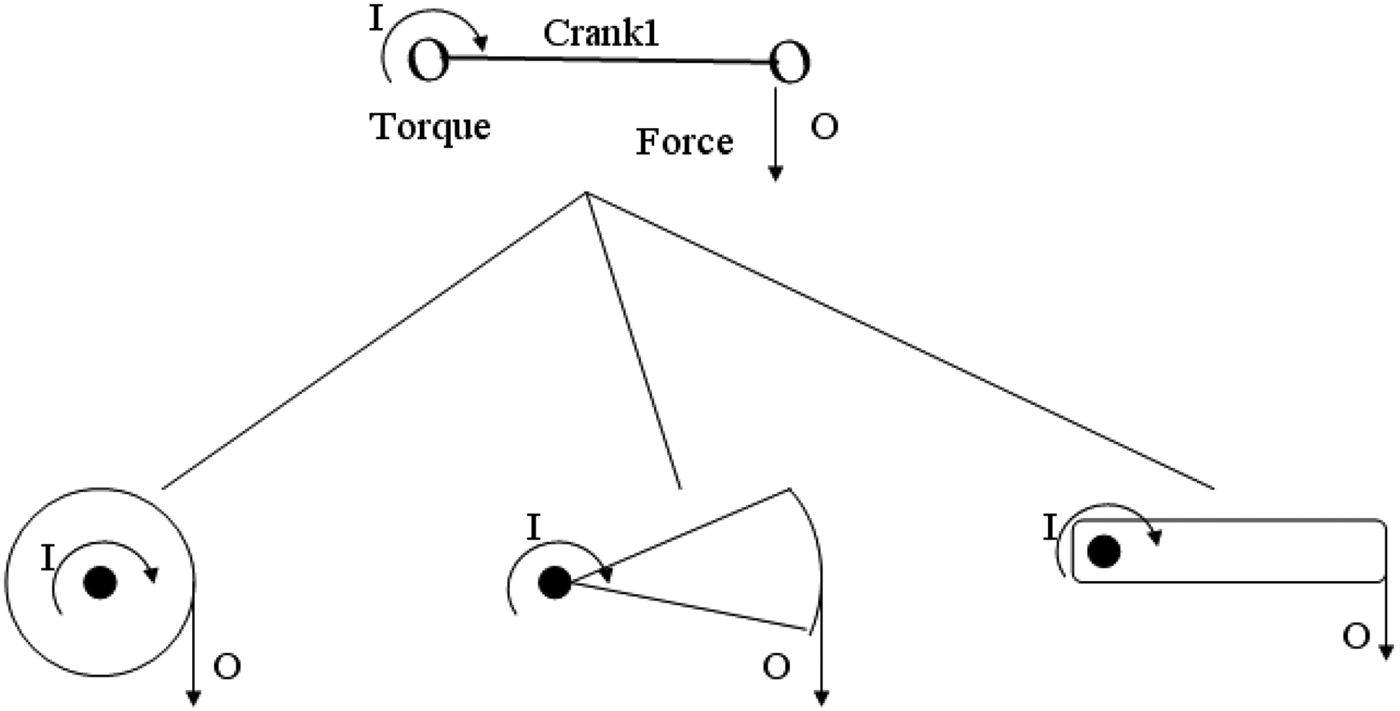
Crank1 building block, in one of its forms, is a plate (circular disc), for which one possible input area is plane, one output area is traction (the rim of the disc), and one support interface is a revolute pair (Figs. 8, 9). A physical embodiment of Crank1 is shown in Table 5; physical configurations of all the building blocks used currently by FuncSION are in Figure 10.
A possible physical structure of the Crank1 building block (Liu, Reference Liu2000).
Crank1 spatial configuration.
Building blocks at the physical level.
Physical building block Crank1 and its attributes
3.2. Representation of a mechanical device
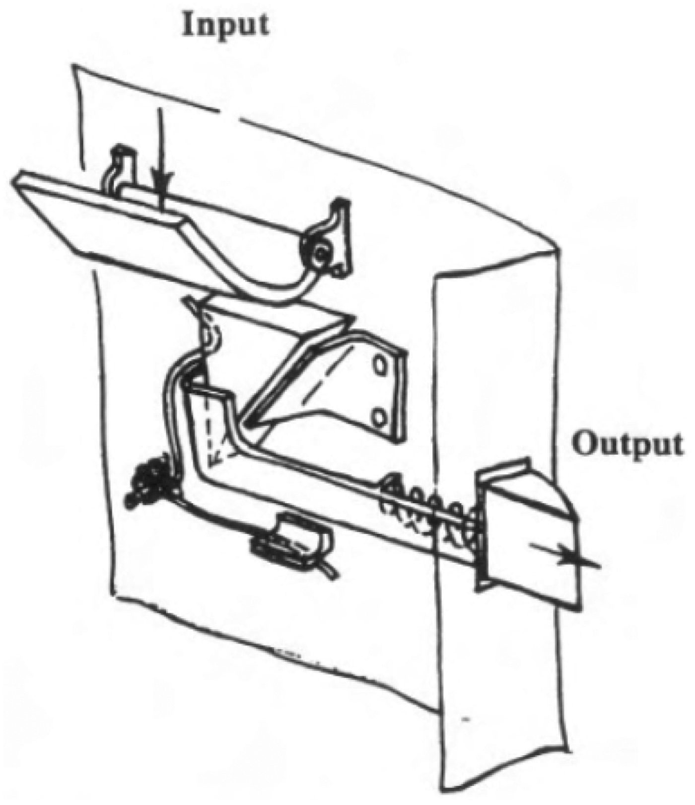
A door latch (Fig. 11) is used as an example mechanical device. As its handle is pressed down, it moves down, causing its output point (wedge) to retract into the casing. If this is continued, finally the handle stops moving down, and with it retraction motion of the wedge. If the handle is released, it moves in the opposite direction, returning the wedge to its original position. This is a temporal sequence of activities defined by temporal changes in the characteristics of the I/O of the device. The characteristics of I/O, in this case, include kinds, for example, force or torque, the directions of their action (e.g., up, down, or sideways), their magnitudes, and their positions.
A physical embodiment of a door latch (Chakrabarti & Bligh, Reference Chakrabarti and Bligh1996c).
The spatial configurations of the I/O of each problem have a definite relationship. In the door latch, the output translation from the handle is transferred to the input of the wedge, which produces a translation at its output that is transferred by the tierod to its output to produce the desired effect (Figs. 12, 13). If the function of each building block is known in terms of its I/O, and if they are appropriately connected so that the I/O match at the connections, they together would provide a causal account of the functioning of the device.
A topological representation of a door latch.
A spatial representation of the door latch.
3.3. Problem representation
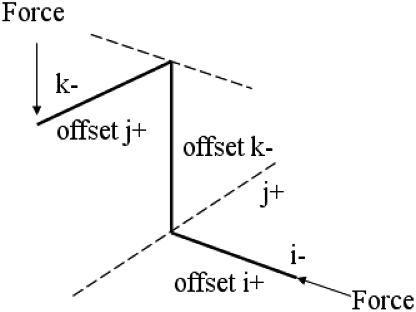
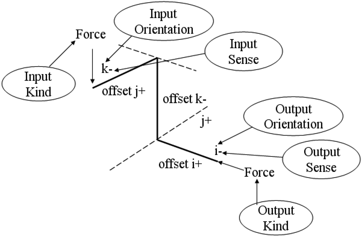
Representation of a design problem needs required I/O kind, which can be force or torque; I/O orientation, which can be i, j, or k (i.e., unit vectors in a Cartesian coordinate system); I/O sense, which can be + or –; and I/O position (i.e., the relative position between I/O vectors).
Using this representation, one can now present, for example, one of the instantaneous functions of the door latch as a vertical downward force input to be transformed into a horizontal leftward translational output (Fig. 14).
Representation of a problem (Liu, Reference Liu2000).
3.4. Solution synthesis by FuncSION
The physical embodiments of concepts are generated using four steps. Kind synthesis generates solutions at the topological level. Alternative spatial configurations for each topological solution are generated by spatial synthesis; for each spatial configuration, alternative physical embodiments are generated using physical synthesis. Building blocks are chosen by the user from 16 building blocks (Table 1). Solutions generated by FuncSION require functional requirements (i.e., I/O kinds, orientations, senses, and positions), a set of building blocks (chosen from the building blocks in Table 1), and the maximum number of building blocks permitted in a solution.
3.4.1. Kind synthesis
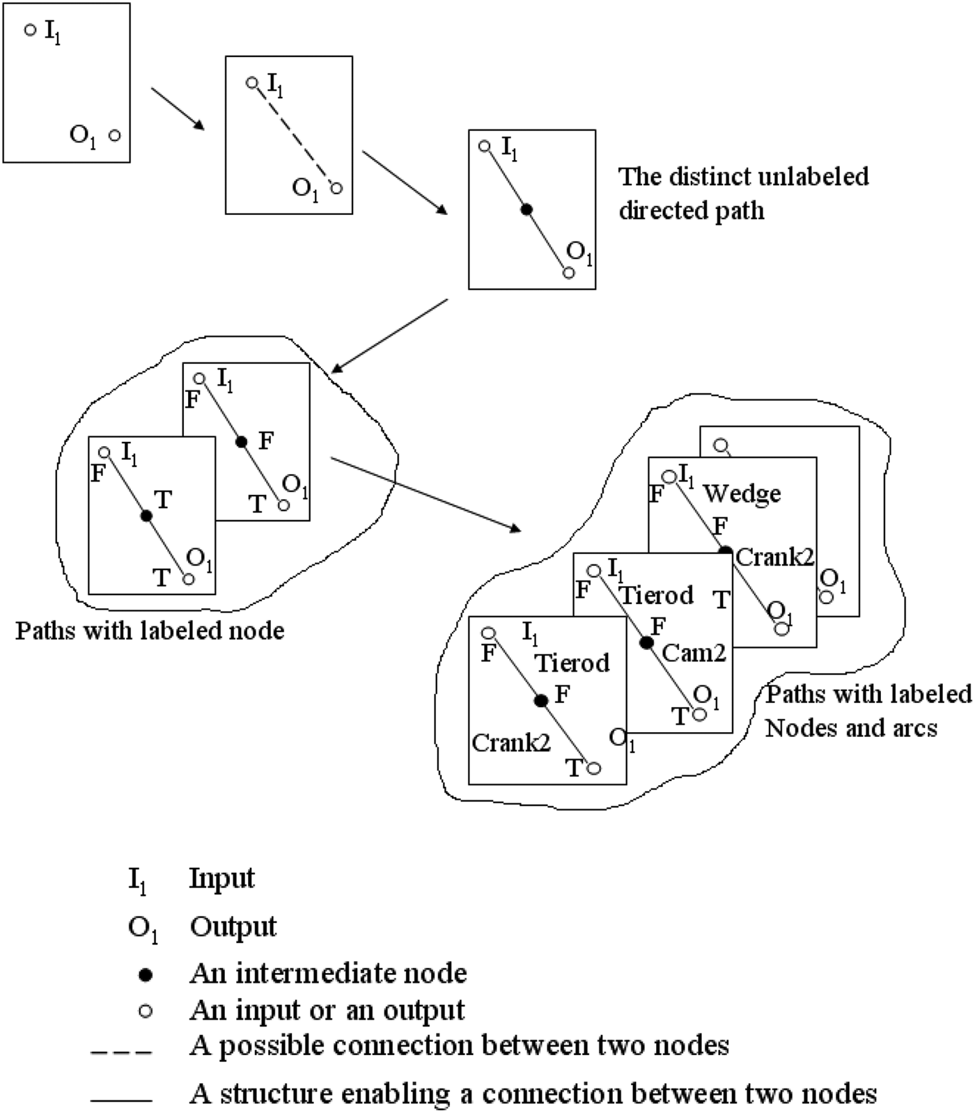
Kind synthesis synthesizes solutions to satisfy the I/O kind requirements. Kind synthesis requires I/O kind, a set of building blocks, and the maximum number of building blocks allowed to be used in a solution, and generates solutions as graphs. For instance, if the maximum allowable number of building blocks is 2, the two possible graphs are a single building block connecting the I/O or two building blocks in series. Each arc in the graph is a building block; each node is an I/O connection. If each node in each path is labeled using the information about the functional requirements and the kinds of I/O that can be handled by the database of building blocks, a number of distinct paths with labeled nodes are obtained. For instance, if the I/O required are force F and torque T, and if the building blocks in the database can only have forces and torques as I/O, the only two possible paths with labeled nodes are F-F-T and F-T-T. If each arc is labeled with each possible alternative building block capable of doing the transformation indicated by the labeled nodes, alternative solutions are found. For instance, in the F-F-T path, if F-F transformation can be done by using either a wedge or a tierod, and the F-T transformation in two ways, by Crank2 or Cam2, the overall function can be achieved by their possible combinations (see Fig. 15; Chakrabarti & Bligh, Reference Chakrabarti and Bligh1994, Reference Chakrabarti and Bligh1996a, Reference Chakrabarti and Bligh1996b).
Generating single-input single-output networks of building blocks (arcs) as solutions to a problem using a database of four building blocks and two building blocks per solution: only one branch of the solution space is expanded above.
The procedure for kind synthesis is summarized below (Liu, Reference Liu2000):
• In the database, each building block is described using its I/O (e.g., Crank1 has torque as the input-kind and force as the output-kind; see Fig. 9).
• The designer selects a set of basic building blocks from the library and specifies the maximum permissible number of building blocks in a solution.
• The designer specifies the I/O requirements in terms of the I/O kind.
• The computer generates all possible combinations of the building blocks that satisfy the interconnection rule and the kind requirements.
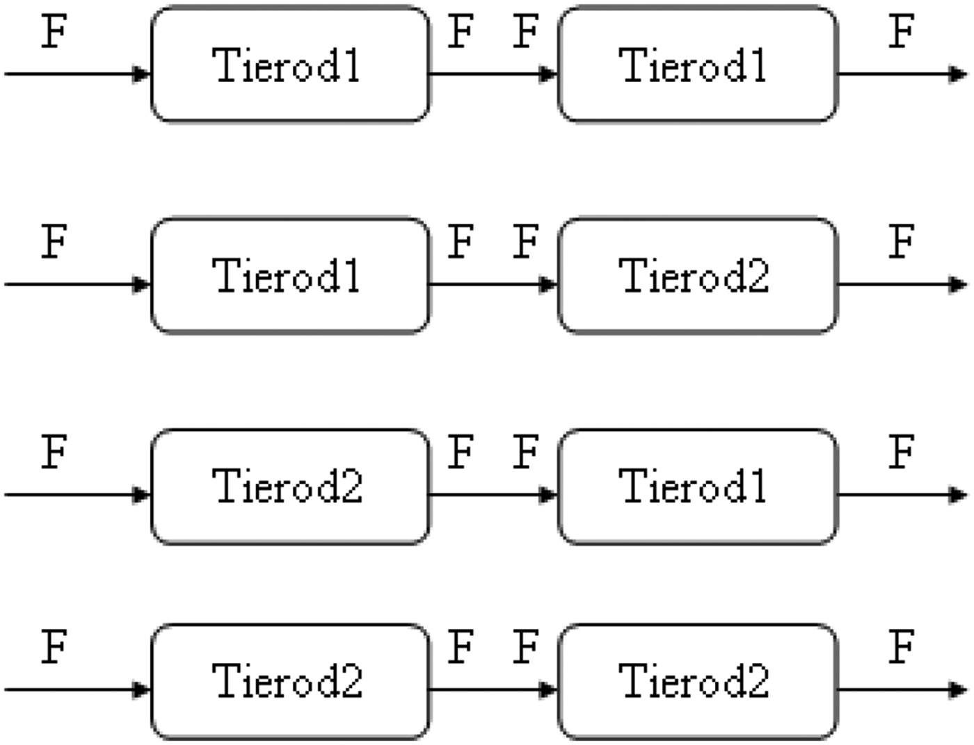
For example, if a design problem is to transform an input force to an output force with a database of only Tierod1 and Tierod2 building blocks, and no solution should have more than two building blocks, four solutions can be generated by kind synthesis: (Tierod1, Tierod1), (Tierod1, Tierod2), (Tierod2, Tierod1), and (Tierod2, Tierod2; see Fig. 16). The interconnection between the building blocks is a force-force connection (Liu, Reference Liu2000).
Example solutions from kind synthesis.
3.4.2. Spatial synthesis
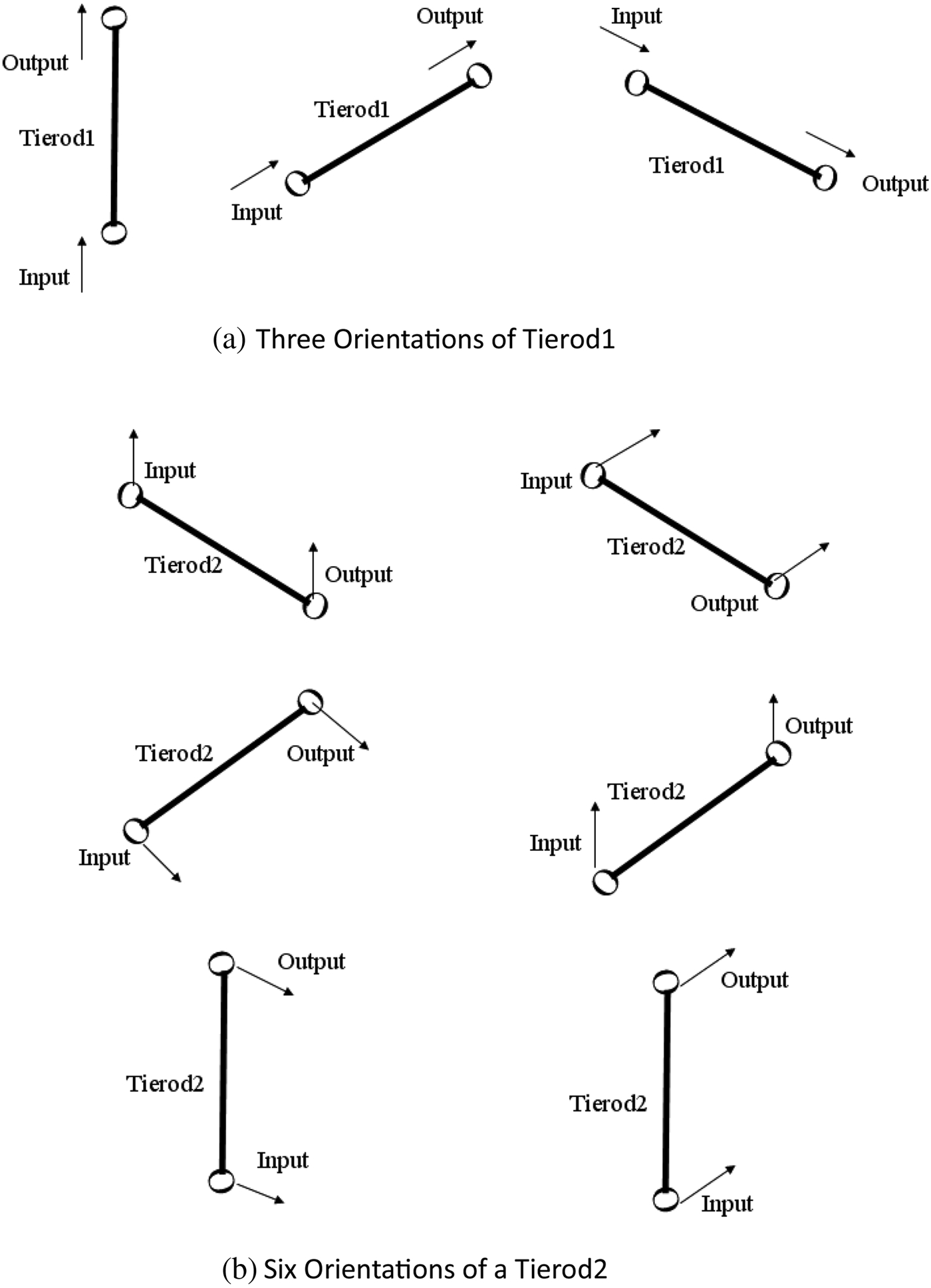
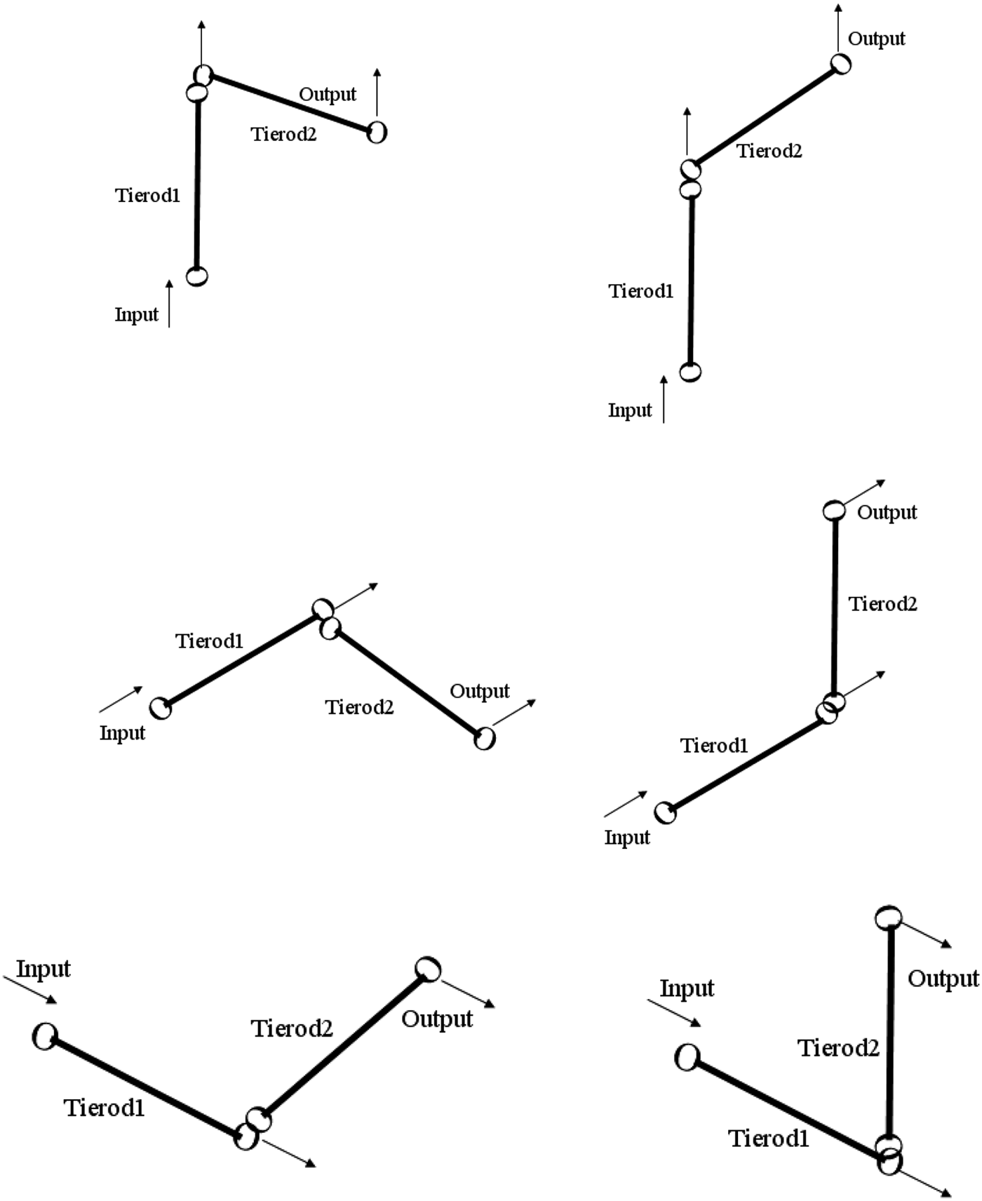
In spatial synthesis, alternative orientation variants for each topological solution are synthesized. Each building block has multiple possible orientations; for example, Tierod1 has three possible orientations (Fig. 17a) and Tierod2 has six possible orientations (Fig. 17b). The orientation alternatives for a building block are determined by possible orientations of its I/O and length vector.
The orientation possibilities for Tierod1 and Tierod2 (Liu, Reference Liu2000).
Each topological solution has multiple orientation configurations based on specific combinations of orientation possibilities of its building blocks. Spatial synthesis generates all possible solutions that satisfy the stipulated I/O orientations. A topological solution with Tierod1 and Tierod2 has six possible orientation configurations (Fig. 18). In orientation synthesis (Liu, Reference Liu2000),
• The designer selects a topological solution for orientation synthesis, from the set of topological solutions generated in the topological synthesis step.
• The designer specifies the I/O orientation requirement.
• The computer generates all possible orientation configurations of the topological solution that satisfy the interconnection rule and the orientation requirement.
• The computer repeats the above three steps for each topological solution.
Six orientation configurations of a topological solution (Tierod1 and Tierod2; Liu, Reference Liu2000).
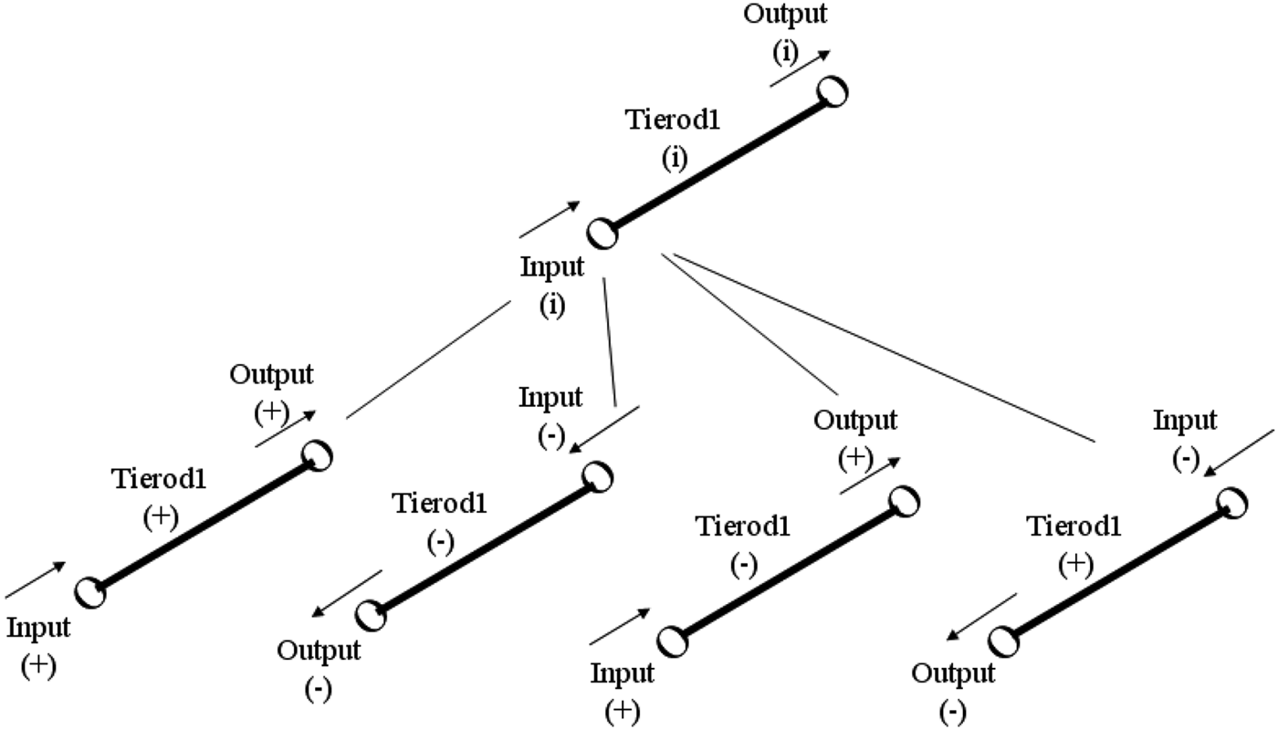
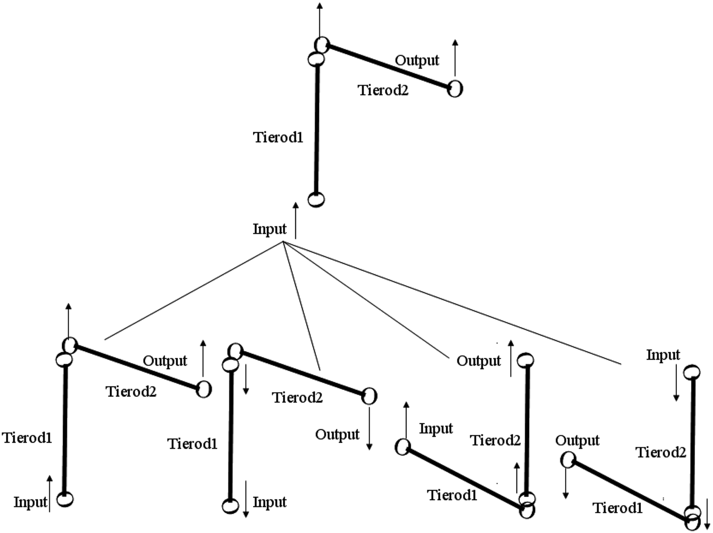
The next step, sense synthesis, is similar to orientation synthesis, except for changing the consideration of orientation to sense. Each vector can have a positive (+) or a negative (–) sense for the same orientation. For instance, Tierod1 with orientation along the i axis has 4 possible spatial directions (Fig. 19). Because Tierod1 can be spatially oriented along the i, j, or k axis, it has 12 (3 × 4) possible spatial orientations. Alternative spatial orientations of a building block are decided by the sense of its I/O and length vector, for example, in an orientation configuration where Tierod1 is oriented along the k axis, and Tierod2 along the i axis, there are 4 possible spatial configurations (Fig. 20; Liu, Reference Liu2000). In sense synthesis (Liu, Reference Liu2000),
• The designer selects an orientation configuration for sense synthesis, from the set of orientation configurations generated from the orientation synthesis step.
• The designer specifies the I/O sense requirement.
• The computer generates all possible spatial configurations of the orientation configuration that satisfies the interconnection rule and the sense requirement.
Four spatial possibilities derived from one orientation possibility (Liu, Reference Liu2000).
Four spatial configurations derived from one orientation configuration (Liu, Reference Liu2000).
3.4.3. Physical synthesis
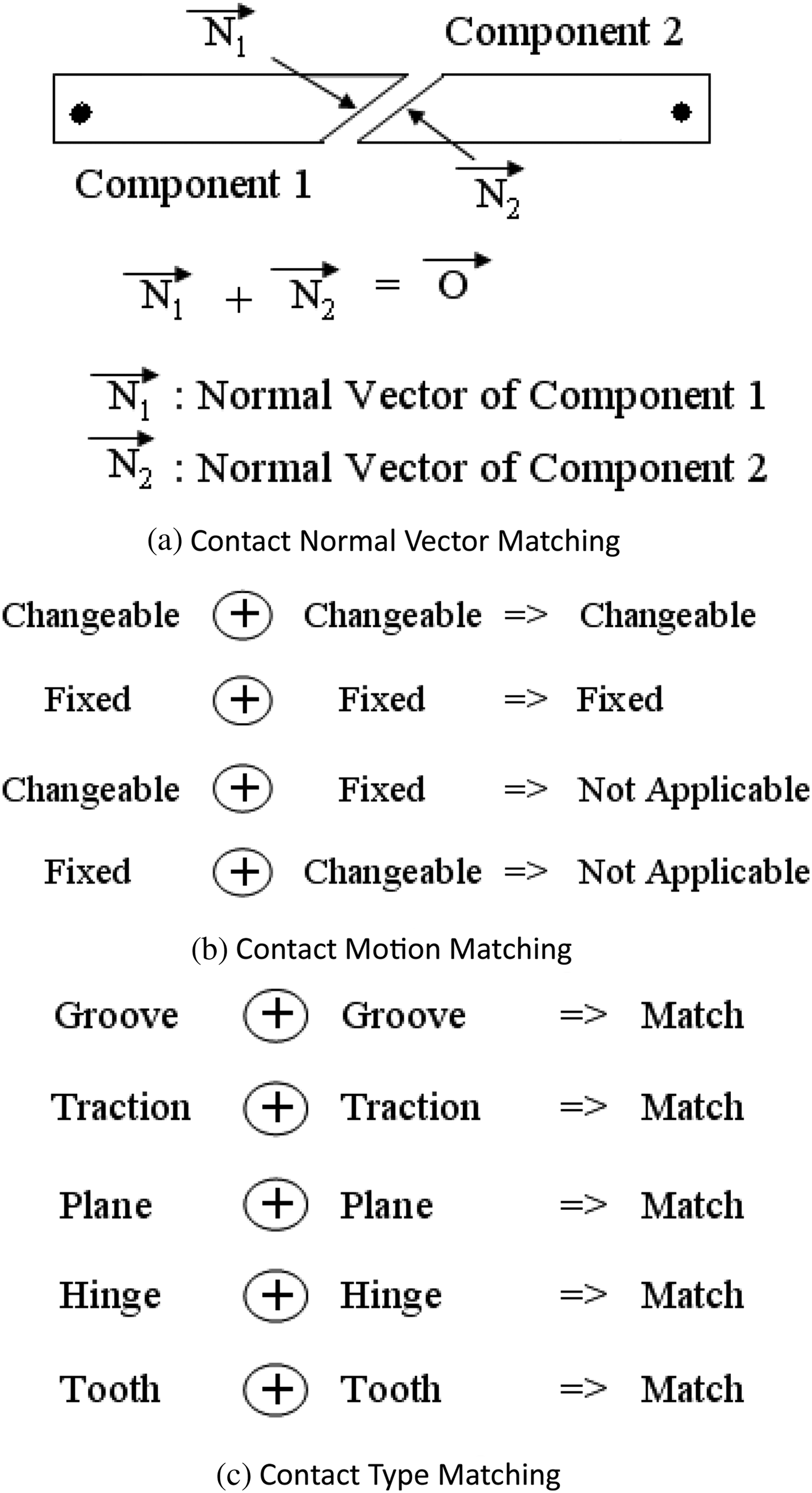
In physical synthesis, possible, alternative physical embodiments for spatial solutions are generated. Each spatial building block in a spatial solution has various alternative generic physical building blocks with various forms, support interfaces, and motion interfaces. Considering all possible combinations of the spatial building blocks' generic physical building blocks, alternative physical embodiments of the solution, which meet the rule of motion interface compatibility for all connecting building blocks, are generated. Connections between these building blocks contain kinds; directions of the kinds, position of building blocks; and the motion interface with the matching normal vector, motion, and type (Liu, Reference Liu2000; Fig. 21a–c).
Rules for motion interface compatibility (Liu, Reference Liu2000).
To transform a spatial solution into a physical solution, the computer must replace each spatial building block in the spatial solution with possible physical building blocks that can represent that spatial building block and can be physically connected to possible physical building blocks that can represent the spatial building blocks to which the spatial building block is connected. The process of matching between two sets of objects (each set containing alternative physical embodiments of a spatial building block) selects an alternative from each set and evaluates whether the output area of the former building block and the input area of the latter building block obeys the rule for motion interface compatibility. This process is repeated for all alternative combinations (Fig. 22).
Different embodiments of the Crank1 building block (Liu, Reference Liu2000).
4. SOLUTION SYNTHESIS BY FuncSION: AN EXAMPLE
Synthesis by FuncSION is described with a door latch device as the example. For this device, the functional requirements are taken as
• input-kind and output-kind: force and force
• input and output orientation: k and i
• input and output sense: – and –
Figure 23 shows the GUI of FuncSION. The top left box is for specifying the functional requirements. The user can specify up to 12 (i.e., combinations of 2 kinds, 3 orientations, and 2 senses) different variants of input or output, with a number of possible, qualitative positions. Input is specified at the central yellow dot of the cube; output is specified at any other yellow dot on the cube (Fig. 24). The user also selects the maximum number of building blocks allowed in a solution and the set of building blocks (Fig. 25) to be used in synthesis.
FuncSION user interface.
Representation of a functional requirement.
The current set of building blocks.
For the functional requirement specified in Figure 24, a large number of solutions at the topological level are generated by topological synthesis. A sample solution, which has three building blocks, is shown in Figure 26. The solution has two possible spatial configurations (Fig. 27a,b):
 $$\eqalign{\hbox{TierodII} \lpar i-\!\rpar \hbox{TierodII} \lpar j+\!\rpar \hbox{Wedge} \lpar k-\!\rpar \cr \quad \hbox{TierodII} \lpar j+\!\rpar \hbox{TierodII} \lpar i-\!\rpar \hbox{Wedge} \lpar k-\!\rpar }$$
The first spatial solution (Fig. 27a) has three different physical level solutions (Fig. 28a–c).
A topological-level solution generated by FuncSION.
Two alternative spatial-level solutions generated by FuncSION.
Three alternative physical-level solutions generated by FuncSION.
5. EVALUATION OF FuncSION
5.1. Experimental procedure
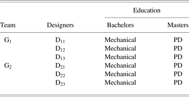
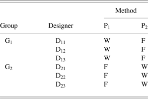
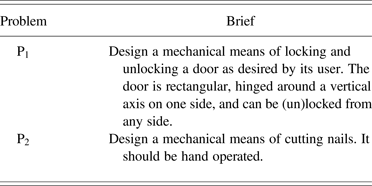
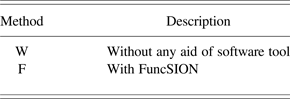
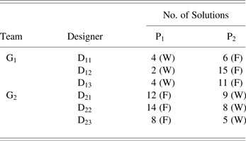
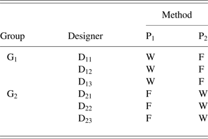
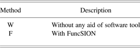
A comparative study involving 12 design exercises was carried out to evaluate FuncSION for the effectiveness of its outcomes in stimulating design ideation. Two groups of three individual designers were used in the study (Tables 6, 7). All were novice designers with bachelor's degrees in mechanical engineering; all had been pursuing master's degrees in product design and engineering at the time when these sessions were conducted. The design exercises were conducted in laboratory settings. Designers in each group individually solved two different problems (Table 8), one without and the other with the aid of outputs from FuncSION (Table 9). Designers of each group were asked to individually design; the outputs were sketches of their solutions with brief descriptions providing explanation. Each participant was asked to generate as many conceptual solutions as they could during the 90 min of each design session.
Designer's background
Note: PD, Product design.
Design sessions
Problem briefs
Design methods
During the design sessions with outputs from FuncSION, designers were asked to choose 2 input and 2 output descriptions from FuncSION (i.e., each with a distinct combination of kind, sense, orientation, and position) for defining the functions to represent the design problem given. Thus, 4 (2 × 2) alternative I/O descriptions were generated for each problem by each designer. For each I/O description, 6 different physical-level solutions (chosen randomly from the large set of solutions generated by the software using that I/O description) were shown, one at a time, to the designer, who was asked to generate as many conceptual solutions as he could with inspiration from the solution shown. Therefore, a total of 24 (6 × 4) solutions were shown as stimuli for each problem to each designer.
The above experimental procedure was designed for several reasons. The first was to minimize the effect of designers and problems on the outcomes: by forming two groups and using two problems. Second, individual designers were asked to solve problems without and with the aid of stimuli from FuncSION, in that order, to overcome the effect of FuncSION while they solved the problem without its aid. Third, only 24 solutions among a larger set generated by the software were shown to each designer owing to the time constraint. Figures 29 and 30 show the collection of all functional requirements considered by the designers during the sessions with FuncSION.
Various input–output combinations considered by designers for Problem 1.
Various input–output combinations considered by designers for Problem 2.
A topological solution generated by FuncSION for one specified functional requirement (Fig. 31) consists of three physical building blocks: CrankII, Belt, and Cam1 (Fig. 32); these building blocks are respectively orientated along j+, k–, and k– (Fig. 33); a physical embodiment of the solution is shown in Figure 34. Inspired by the solution generated by FuncSION (in Fig. 34); one designer created a solution for Problem 2 as shown in Figure 35.
One functional specification for Problem 2.
A topological solution generated by FuncSION for the functional specification in Figure 31.
A spatial-level solution generated by FuncSION for the topological solution in Figure 32.
A physical-level solution generated by FuncSION for the spatial solution in Figure 33.
A solution generated by a designer for Problem 2 with the solution in Figure 34 as stimulus.
5.2. Results and discussion
Table 10 gives an overview of the number of design solutions generated by the individual designers for their design problems, without and with the aid of stimuli from FuncSION. From the comparative data in Figures 36 and 37, FuncSION seems to have a strong positive influence on the number of concepts generated, which on average is 171% more when using outputs from FuncSION, compared to when not. What is promising is that FuncSION, with a limited number of stimuli used in the exercise, still accounts for about 67% of all concepts generated, indicating that a greater number of outcomes from FuncSION, used as stimuli, would have led to an even greater number of concepts generated by designers.
Solutions generated by the individual designers in Group 1.
Solutions generated by the individual designers in Group 2.
Number of solutions generated during the design sessions
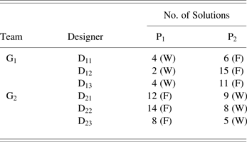
Note: W, Without stimuli from FuncSION; F, with stimuli from FuncSION.
In sessions aided by FuncSION, designers could either modify or directly use the solution generated by FuncSION. Because design problems are combinations of many instantaneous functions, designers often modified stimuli from FuncSION to ensure that their solutions satisfied the functional requirements.
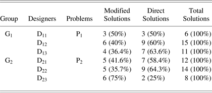
In the sessions aided by FuncSION, an average of 47% of the solutions generated by designers was inspired by FuncSION (where only part of the stimulus was used in the solution generated by the designer), whereas 53% was taken directly from FuncSION (where the whole solution suggested by FuncSION was utilized in the solution created by the designer); see Table 11.
Number and percentage of direct and inspired solutions
Figures 38–41 show two cases of direct and inspired solutions for Problem 1 and Problem 2. Figure 38 shows a solution generated by FuncSION for Problem 1. Figure 39 shows a solution created by a designer, a modified version of its inspiration in Figure 38. The functional requirement specified by the designer was to convert a force along the k– axis to a force along the j– axis. The solution produced by FuncSION uses TierodI (k–), CrankII (j+), and CrankI (j+). The solution is modified by the designer using two rack-and-pinion arrangements (Fig. 39). The first rack is moved by the user to cause the second rack to move forward/backward, for opening/closing the door.
A solution generated by FuncSION for Problem 1.
Solution generated by a designer using the solution in Figure 38 as stimulus.
A solution generated by FuncSION for Problem 2.
Solution generated by a designer using the solution in Figure 40 as stimulus.
Figure 40 shows a solution generated by FuncSION for Problem 2. Figure 41 shows a solution created by a designer, inspired by and adopting directly the solution in Figure 40. The functional requirement specified by the designer was to convert a force along the k– axis to a force along the k– axis. The solution produced by FuncSION consists of a TierodI (k–), CrankII, (j+), and CamI (k–). As TierodI translates, it causes CrankII to rotate, rotating CamI, to which CrankII is connected. If the follower of CamI is designed as a cutter, the mechanism can be used as a nail cutter.
6. SUMMARY AND CONCLUSIONS
The theory behind FuncSION is outlined as follows: its knowledge representation and reasoning schemes for synthesizing solutions using building blocks at different abstraction levels are elaborated, before explaining how its GUI can be used for generating solutions to given requirements. A comprehensive evaluation of the effectiveness of the outputs from FuncSION for stimulating ideation by engineering designers has been described. The results demonstrate that FuncSION helps generate a much larger set of solutions than designing unaided.
The amounts of time spent in the design sessions without and with the aid of FuncSION are almost the same. Therefore, for the same time duration, the same designers generated a greater number of solutions with the aid of FuncSION, which means improved ideation fluency.
However, because not all solutions produced by FuncSION were possible to be shown to the designers in the brief time frame of the design sessions, it is argued that there is scope for further improvements in ideation fluency if a larger number of solutions from FuncSION could be shown in an efficient manner. Overall, the results indicate that a FuncSION-like support could have substantial positive impact on design ideation.
The study opens up several directions for further research:
• The current study used relatively few, novice designers in two problems only, owing to the amount of time it takes to carry video protocol studies on each design session and owing to relative lack of availability of more experienced designers. Further work should focus on extending the number of studies with more experienced designers and more problems.
• The current study focused on ideation fluency and used existing literature to conclude its influence on variety and novelty. Further work should also evaluate variety, novelty, and creativity of designs in the studies.
ACKNOWLEDGMENTS
Sincere thanks to all participant designers who must remain anonymous for reasons of confidentiality.
Ujjwal Pal received a bachelor's degree in mechanical engineering from the National Institute of Technology, Durgapur, India, and a master's in engineering from the Centre for Product Design and Manufacturing, Indian Institute of Science (IISc), Bangalore, India. Before and after his master's work, he worked as a member of the research staff at IdeasLab at IISc, Bangalore, where he worked on a variety of projects funded by the Indian Space Research Organisation; the Boeing Company USA; IMI-Vision, United Kingdom; and so forth. His research interests include biomimetics, functional synthesis, and conceptual design.
Ying-Chieh Liu is an Assistant Professor in the Department of Industrial Design at Chang Gung University, where he teaches design engineering, design method, and design project management. Prior to joining the university, he worked for 12 years in the field, including 4 years in international projects in United States. He received his PhD from the University of Cambridge. Dr. Liu is familiar with new product design, engineering design process (from system definition to life cycle support), and project management. He received a certificate as a Project Management Professional.
Amaresh Chakrabarti is a Professor at the Centre for Product Design and Manufacturing, IISc, Bangalore, India. He has a bachelor's degree in mechanical engineering (University of Calcutta), a master's in mechanical design (IISc), and a PhD in engineering design (University of Cambridge). After obtaining his PhD, he led the design synthesis team at the Engineering Design Centre at University of Cambridge for 10 years before joining IISc. His interests are in design synthesis, creativity, sustainability, and product informatics. Dr. Chakrabarti coauthored DRM: A Methodology for Design Research. He is an honorary Fellow of the Institution of Engineering Designers, United Kingdom. Seven of his papers have won top paper awards in international conferences.