Introduction
During the past few years, the demands for wireless high data rate over multibands/wideband frequency spectrum have increased significantly. To fulfill these demands, the frequency spectrum 3.1–10.6 GHz is allocated to ultrawideband (UWB) applications for unlicensed usage in 2002. This approval stimulated the interest for investigating wideband antenna structures fulfilling these demands. The approved frequency spectrum covered only the short-range communication services but not the long-range communication range. To fulfill both frequency spectrums, i.e. long-range and short-range communication services, the term super wideband (SWB) technology was coined. A technology having ratio bandwidth of ≥10:1 is defined as SWB technology. Few planar antenna geometries having miniaturized dimensions and super wide bandwidth are already proposed.
Another challenge for these wideband wireless antenna structures is the mitigation of fading effects in multipath environments. These signal fading effects are mitigated by integrating the multiple-input multiple-output (MIMO) technology with UWB/SWB antenna structures. This integration led to an increase in the channel capacity. MIMO technology uses multiple uncorrelated antenna structures for transmission and reception purpose. Few wideband MIMO antenna structures are already available in the literature [Reference Nezhad and Hassani1–Reference Debnath, Karmakar, Saha and Huda24]. These reported structures included both spatial (i.e. same radiation patterns) and pattern (i.e. different radiation patterns) diversity configurations. In most of these MIMO configurations, the inter-port isolation between the two ports is enhanced by using various decoupling structures which include grounded stubs, neutralization lines, inter-digital structures, diagonal structures, etc.
From the available literature, it is observed that the previously reported structures have either large dimensions or bandwidth unable to cover UWB frequency spectrum or beyond it. In the available literature, antenna designers [Reference Debnath, Karmakar, Saha and Huda24–Reference Raheja, Kanaujia and Kumar33] have used FR-4 epoxy substrate due to its low cost. On the other side, some researchers have avoided it due to its losses at millimeter range frequencies [Reference Manohar, Kshetrimayum and Gogoi34, Reference Huang and Boyle35].
In this paper, two diversity antenna configurations, i.e. spatial and pattern that are of a feather-shaped SWB antenna, are presented. The feather-shaped radiating patch is designed by using multiple rotated elliptical monopoles. The bandwidth is enhanced by using the techniques of circular slot loading of the radiating patch, modified quarter elliptical coplanar waveguide (CPW) ground planes, and rectangular notch loading of the ground plane. The isolation in spatial diversity configuration is enhanced by placing two antenna elements in coplanar manner with a distance of λ/10 between the two radiating elements. The isolation between the two orthogonal antenna elements in pattern diversity configuration is enhanced by using a diagonal metallic strip. The single antenna element and both diversity configurations are designed and analyzed by using FEM-based Ansoft's HFSS Simulator.
Antenna design
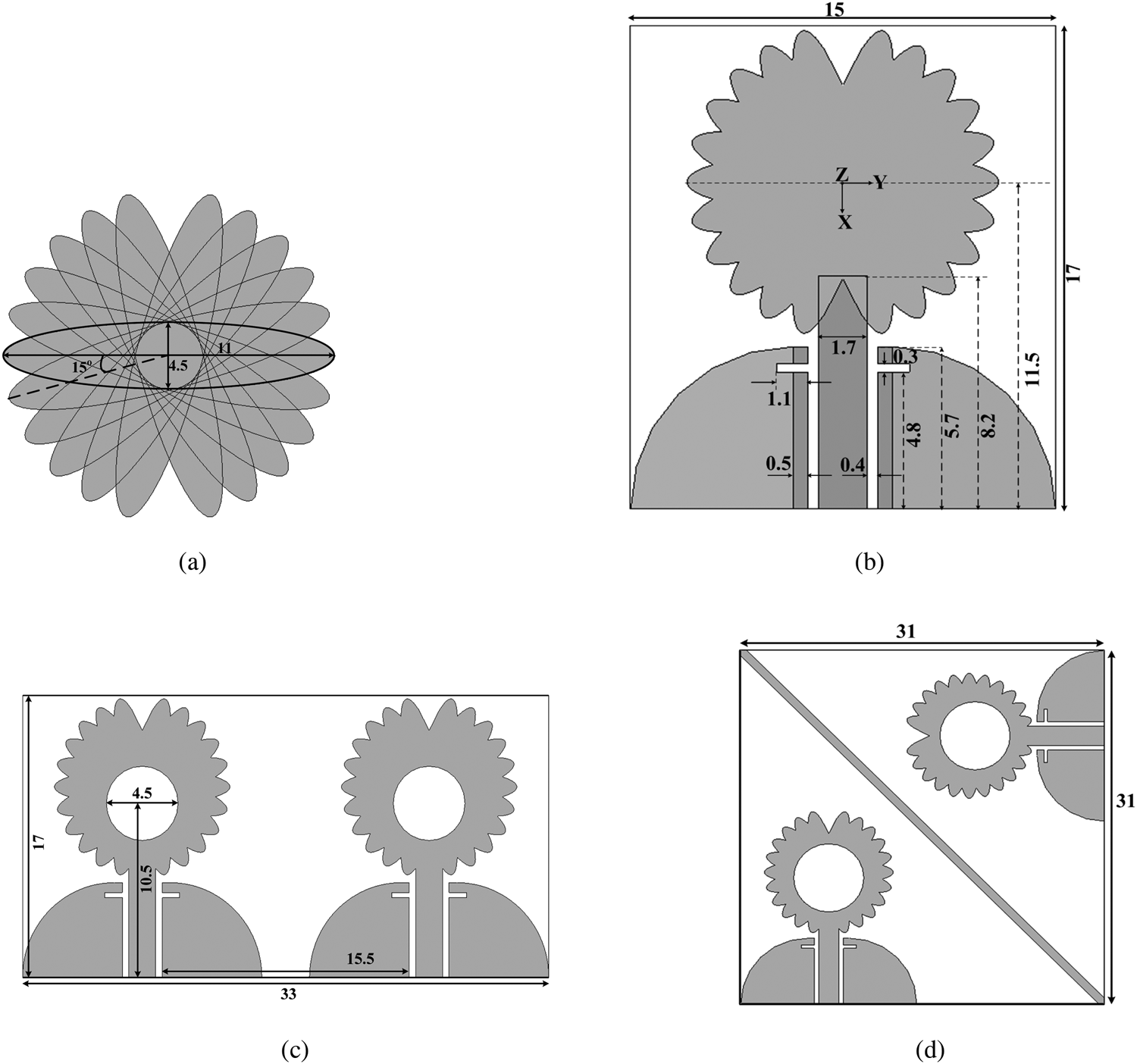
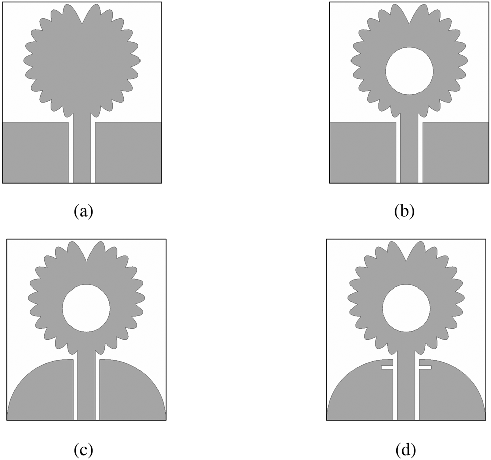
The optimized antenna configurations are presented in Fig. 1. The material used as a substrate in both configurations is 1.6 mm-thick FR-4 epoxy. The feather-shaped monopole comprises of 11 rotated elliptical radiators. This monopole is fed by conventional rectangular microstrip feedline designed according to antenna design equations. A central circular slot is loaded on the radiator geometry to enhance the bandwidth by improving impedance matching. Thereafter, a pair of rectangular notches is loaded on the modified CPW ground plane to further improve the impedance matching and enhance the overall impedance bandwidth. The ground plane comprises of quarter elliptical and rectangular metallic sections. The antenna element design steps are demonstrated in Fig. 2. During the systematic optimization of antenna dimensions, one dimension is varied while keeping all other dimensions fixed.
Antenna configurations. (a) Radiating patch. (b) Single antenna. Spatial diversity configuration (Ant I). Pattern diversity configuration (Ant II).

Antenna element design steps. (a) Without central slot. (b) Conventional partial ground plane. (c) Without ground notches. (d) Proposed antenna.

In spatial diversity configuration, two elements are arranged on the same side of the substrate with a fixed distance of λ/10 between the radiating patches without any additional decoupling structure. For pattern diversity configuration, two identical antenna elements are arranged orthogonally with a distance of 3 mm between their radiating elements and a 1 mm-thick metallic strip is placed diagonally across the substrate and coplanar with the antenna geometries.
Results and discussion
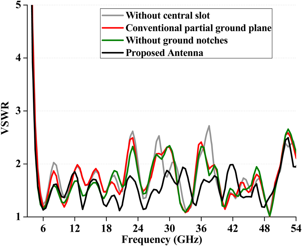
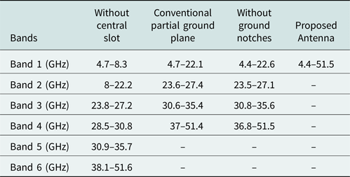
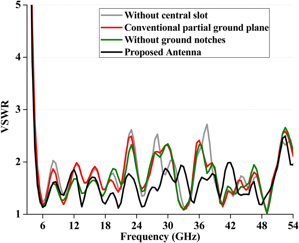
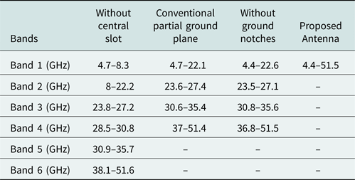
The intermediate antenna element designs are compared in terms of their VSWR characteristics and operating bands in Fig. 3 and Table 1, respectively. It is observed that six operating bands are achieved for antenna without central slot. The central slot loading resulted into the merging of the first two operating bands of above antenna and removal of the fourth operating band with no significant effect on remaining bands. The replacement of rectangular ground plane with modified quarter-elliptical ground plane resulted in bandwidth enhancement for the first and last operating bands of the previous antenna. The loading of the ground plane with rectangular notches resulted in the merging of all operating bands into a single SWB.
VSWR characteristics for intermediate antenna element design stages.
Comparison of antenna element design stages
Frequency domain results
Spatial diversity configuration
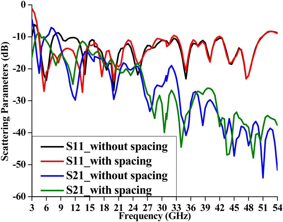
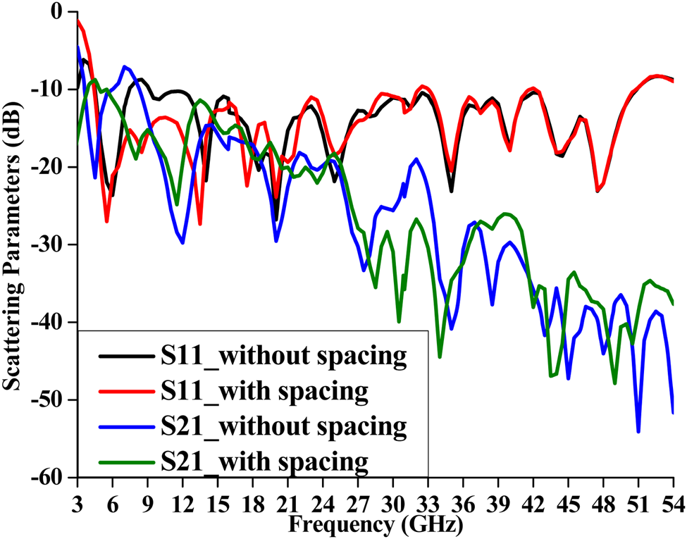
The scattering parameters of spatial configuration with variations in inter-element spacing are presented in Fig. 4. It is observed that the reflection coefficient and isolation improved with an increase in inter-element spacing from 0 to 2 mm.
Scattering parameters of spatial diversity configuration with variations in inter-element spacing.
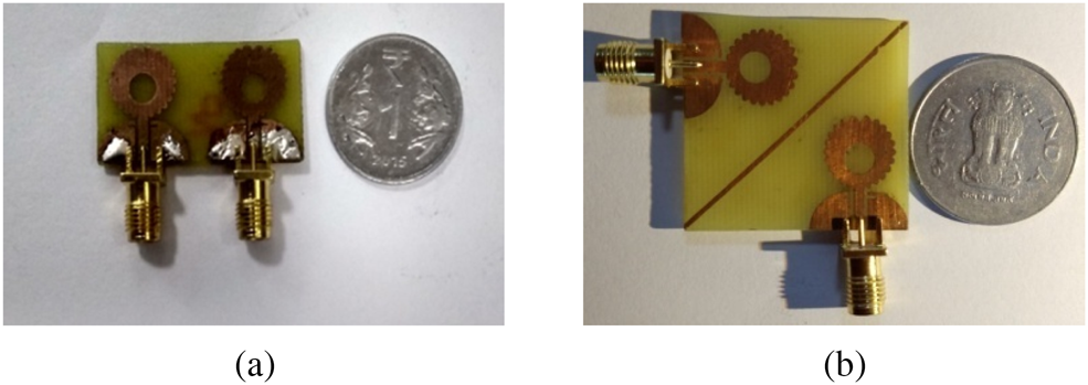
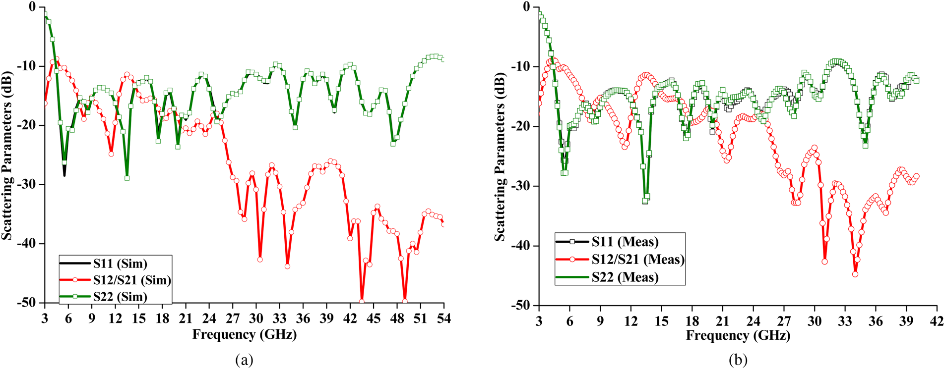
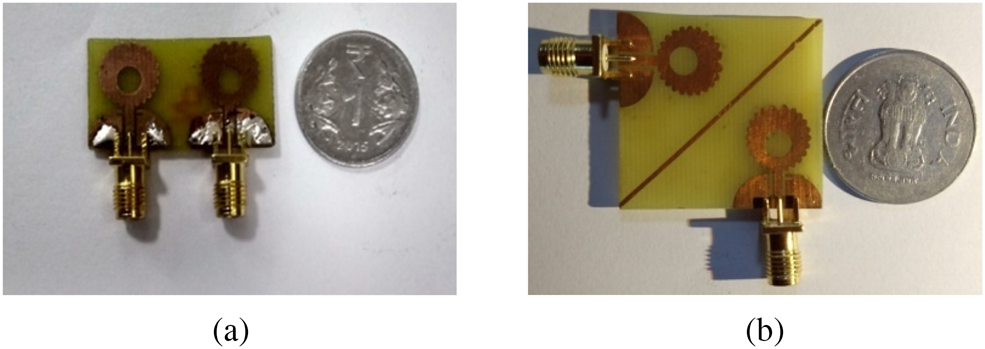
The MIMO antenna prototypes are presented in Fig. 5. Due to the limitation of available facilities, measurements up to only 40 GHz can be carried out. The variations of scattering parameters with respect to the frequency obtained from HFSS and experimental measurement are illustrated in Fig. 6. The discrepancies between the simulated and experimental results are due to fabrication and soldering errors. Due to the identical antenna elements, this MIMO antenna configuration is a symmetrical network. This symmetry in network leads to equal input impedance at both excitation ports of this MIMO antenna configuration. This impedance equivalence leads to equivalence in reflection coefficient, i.e. S 11 = S 22. The couplings or isolation plots are identical, i.e. S 21 = S 12 because the two-port network is passive and hence reciprocal. Figure 6 demonstrates that both elements have an operating bandwidth (for VSWR ≤ 2) of 4.4–51.5 GHz (~11:1). In addition to this, isolation (S 21 or S 12) ≥15 dB at maximum operating frequencies in the operating band is observed. This isolation fulfills the requirement of MIMO applications.
MIMO antenna prototypes. (a) Spatial diversity. (b) Pattern diversity.
Scattering parameters of spatial diversity antenna configuration. (a) Simulated. (b) Measured.
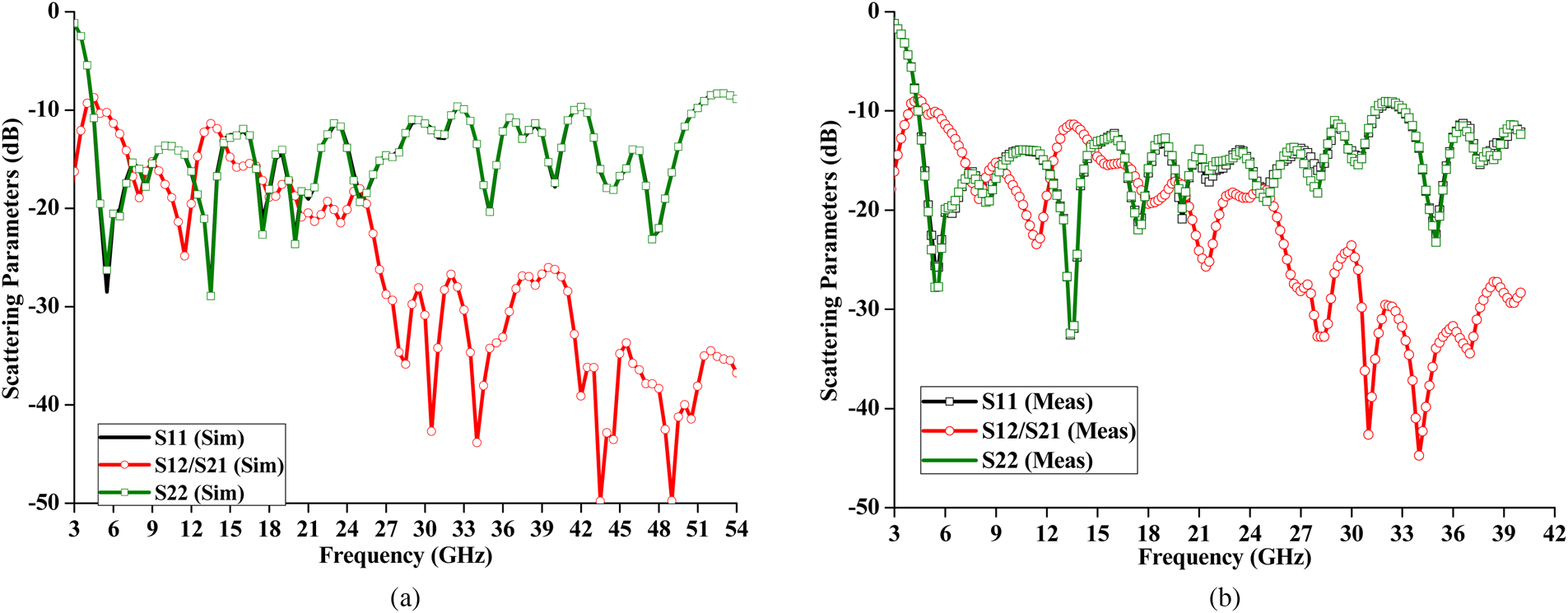
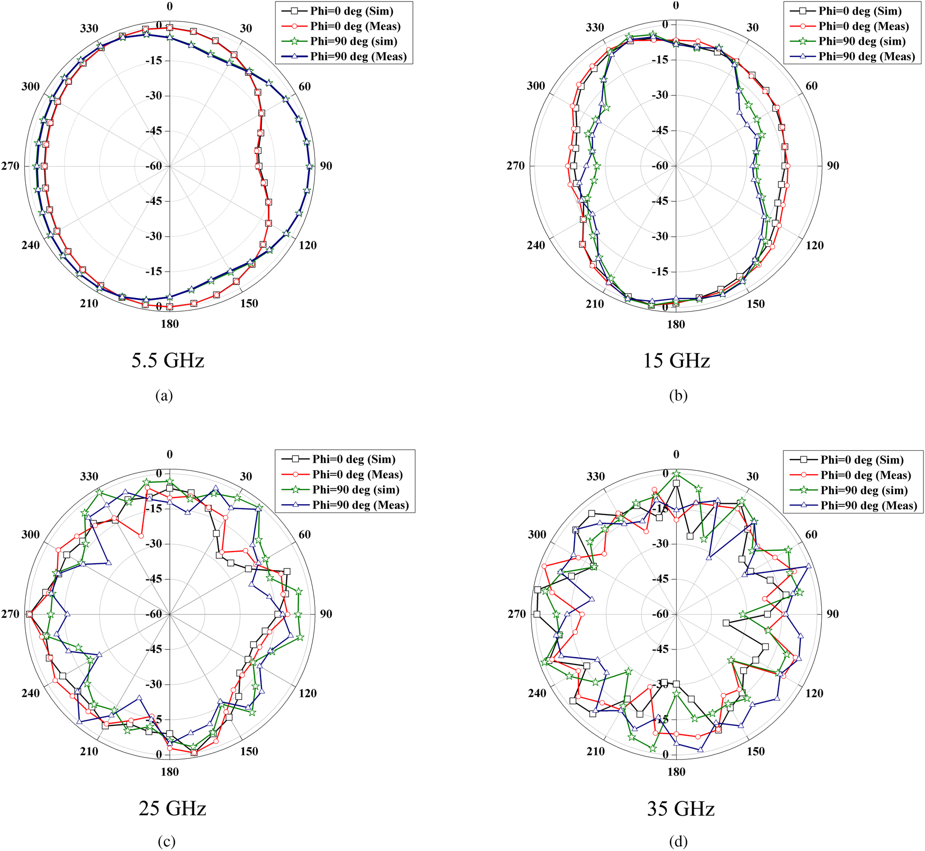
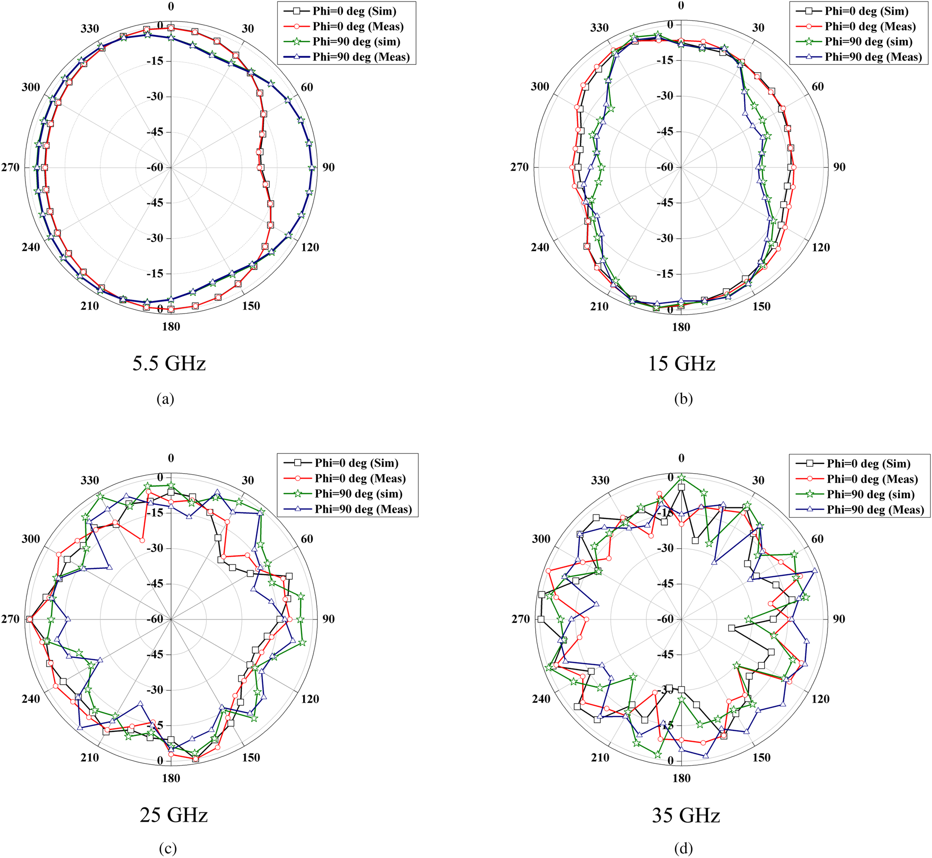
Figure 7 presents that bidirectional and omnidirectional patterns in E-plane and H-plane are achieved at frequencies <10 GHz for both elements. Similarly for frequencies >10 GHz, the patterns acquired distorted omnidirectional nature due to excitation of higher order modes.
Radiation patterns of spatial diversity antenna configuration. (a) 5.5 GHz. (b) 15 GHz. (c) 25 GHz. (d) 35 GHz.
Pattern diversity configuration
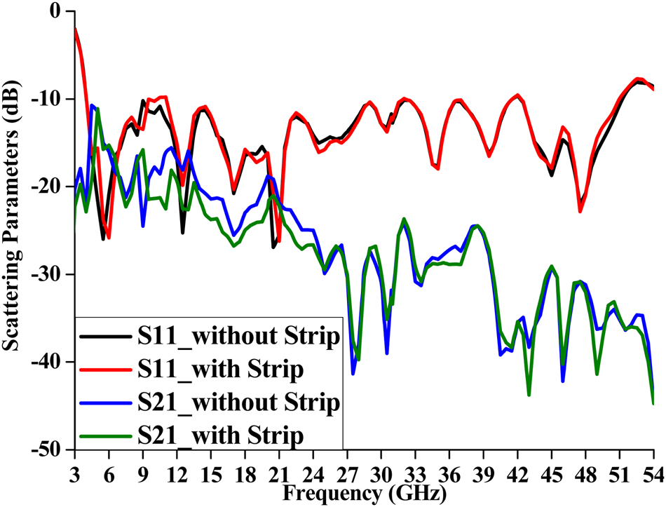
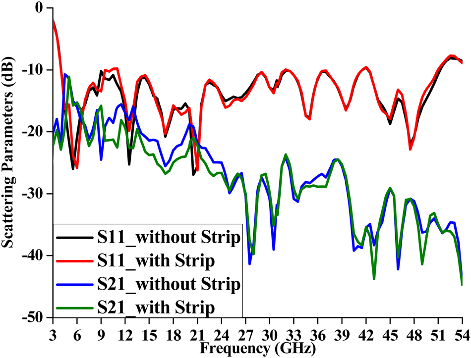
Figure 8 displays the effect of diagonal strip on the pattern diversity configuration performance. It is observed that the reflection coefficient is unaffected, whereas the inter-element isolation is improved with the introduction of diagonal strip between the elements.
Scattering parameters of pattern diversity configuration with and without diagonal strip.
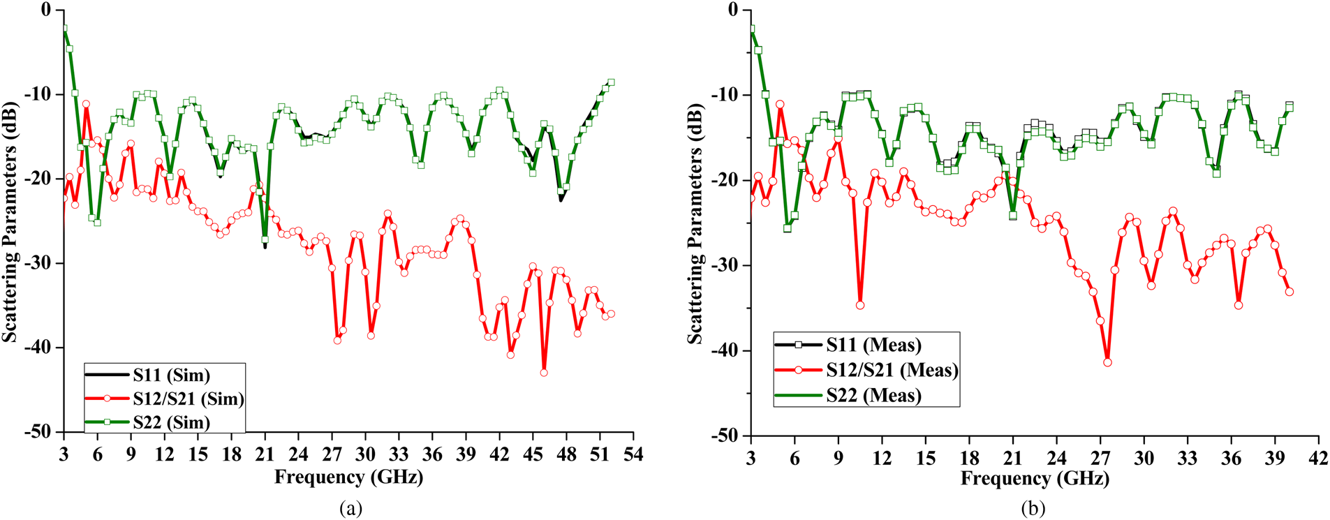
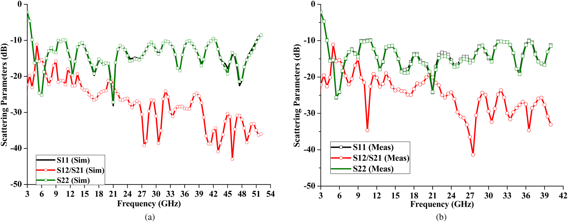
Since the antenna elements are identical, equal input impedance is observed for both ports leading to equal reflection coefficients (S 11 = S 22) and isolation values (S 12 = S 21). Figure 9 illustrates that each element has an operating bandwidth of 3.8–51.5 GHz (~13:1). Except at the frequency of 5 GHz (S 21 = S 12 = 11 dB), the inter-port isolation≥15dB is achieved. The isolation is increasing with frequency. A maximum isolation of 43 dB is achieved. These values of inter-port isolation present a very low level after considering the extreme bandwidth and miniaturized antenna dimensions.
Scattering parameters of pattern diversity antenna configuration. (a) Simulated. (b) Measured.
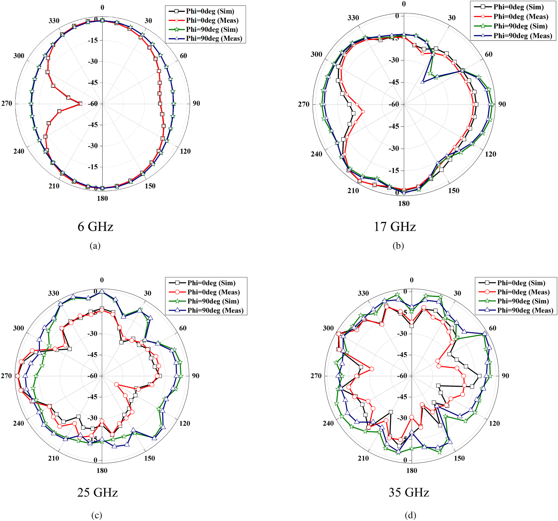
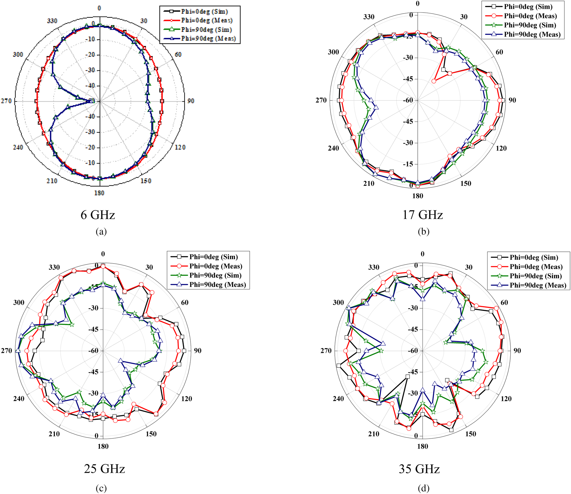
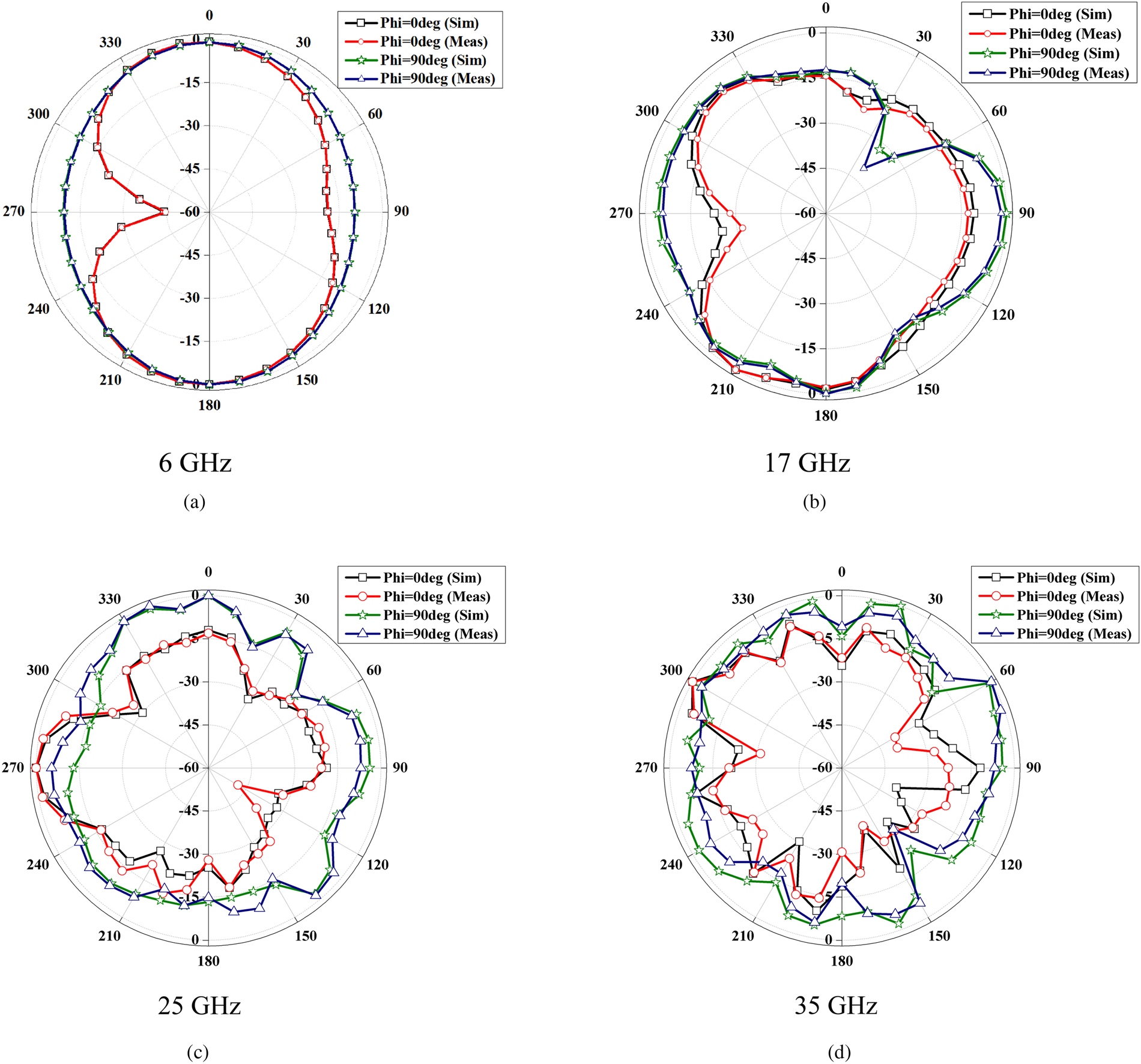
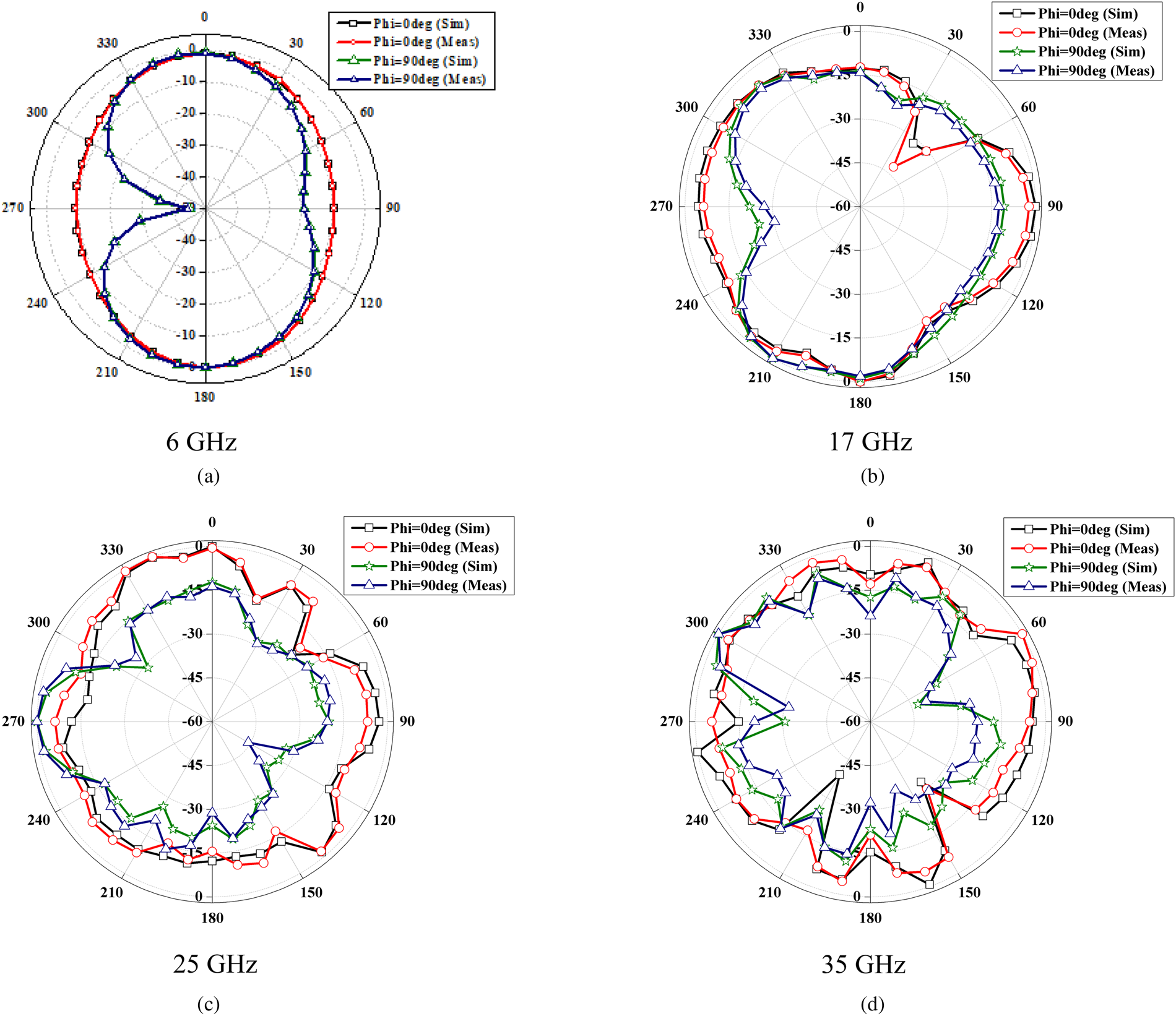
Figures 10 and 11 present the radiation patterns of both elements at some frequency points in both planes. It is observed that the patterns are bidirectional and omnidirectional for frequencies <10 GHz. For higher frequencies, distorted omnidirectional patterns are observed in both planes. The patterns of element 2 are found to be orthogonal to those of element 1 at lower frequencies. In case of higher frequencies, due to the distorted omnidirectional nature, the 90o phase shift in patterns is not easily recognizable.
Radiation patterns of pattern diversity antenna configuration for Port 1. (a) 6 GHz. (b) 17 GHz. (c) 25 GHz. (d) 35 GHz.
Radiation patterns of pattern diversity antenna configuration for Port 2. (a) 6 GHz. (b) 17 GHz. (c) 25 GHz. (d) 35 GHz.
Diversity performance
The effectiveness of a MIMO antenna for diversity applications is measured in terms of the following parameters:
Envelope correlation coefficient (ECC):
It is calculated by using the scattering parameter values through the standard equation (1)[Reference Blanch, Romeu and Corbella36]:

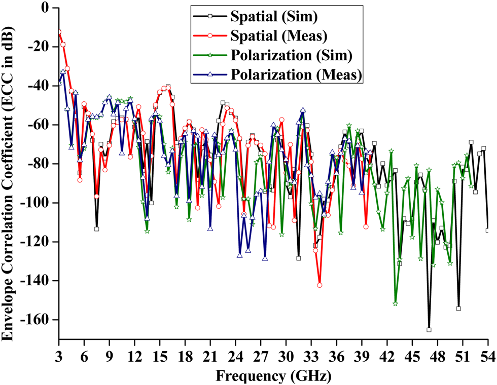
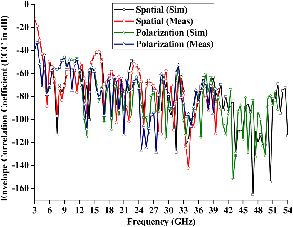
An ECC of 0.5 or −6 dB is the maximum limit for any diversity antenna [Reference Najam, Duroc and Tedjini37]. Figure 12 presents the ECC values for both diversity configurations. For spatial diversity configuration, ECC ≤ −30 dB is observed across a frequency spectrum of 4–24 GHz. Thereafter, ECC ≤ −40 dB is observed at higher frequencies. In case of pattern diversity configuration, −20 ≤ ECC ≤ −30 dB is achieved between 4 and 12 GHz. After 12 GHz, ECC ≤ −40 dB is observed for every frequency in the operating band.
Envelope correlation coefficient for two MIMO configurations.
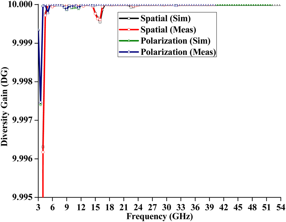
Diversity gain (DG):
It quantifies the diversity effect on the received signal in a multichannel wireless environment. It can be calculated by replacing time-averaged SNR with cumulative distribution function (CDF) in the difference equation given in [Reference Taga38]. The normally used CDF is 1 or 10% [Reference Flaviis, Jofre, Romeu and Grau39, Reference Kildal and Rosengren40]. It is calculated from the above calculated ECC values by using the following relation:
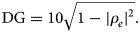
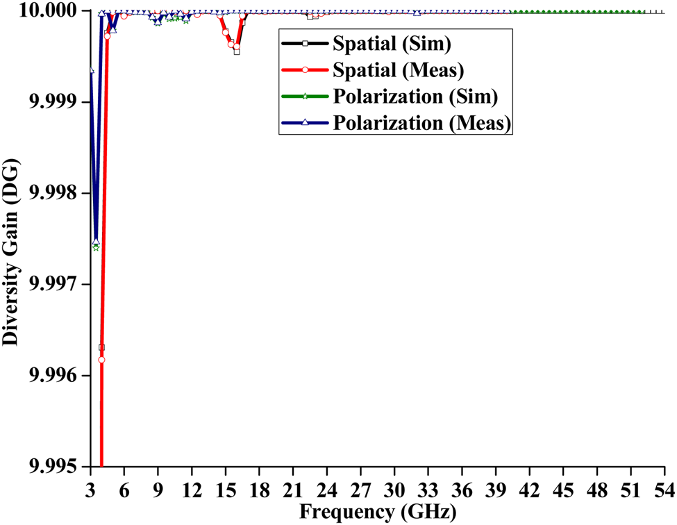
The calculated values of DG are shown in Fig. 13. It is observed that an almost constant DG is obtained across the entire operating band for each configuration.
Diversity gain variations with frequency for two MIMO antenna configurations.
Capacity loss, $C_{{\bf loss}}$

It quantifies the estimated maximum transmission rate in a communication channel in case of rich multipath environment for reliable transmission. For a MIMO antenna, the maximum value accepted in a MIMO antenna is 0.4 b/s/Hz. It is calculated in b/s/Hz by using correlation matrix (3) [Reference Tripathi, Mohan and Yadav41].

where ψ R = correlation matrix of the receiving antenna and is expressed mathematically as


i, j = 1 or 2.
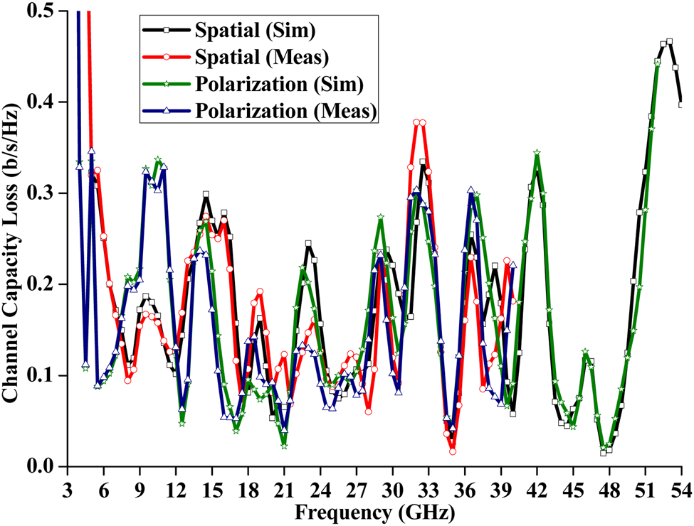
Figure 14 demonstrates that the capacity loss is <0.4 b/s/Hz for each configuration.
Channel capacity loss for two MIMO configurations.

Comparison with other geometries
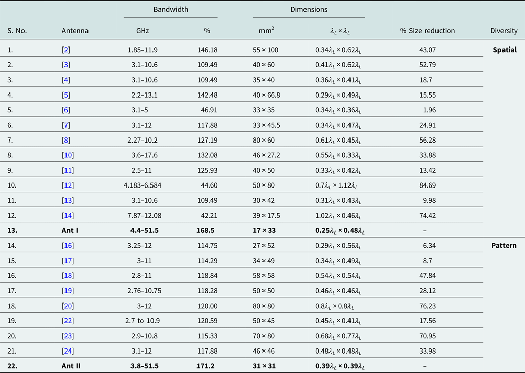
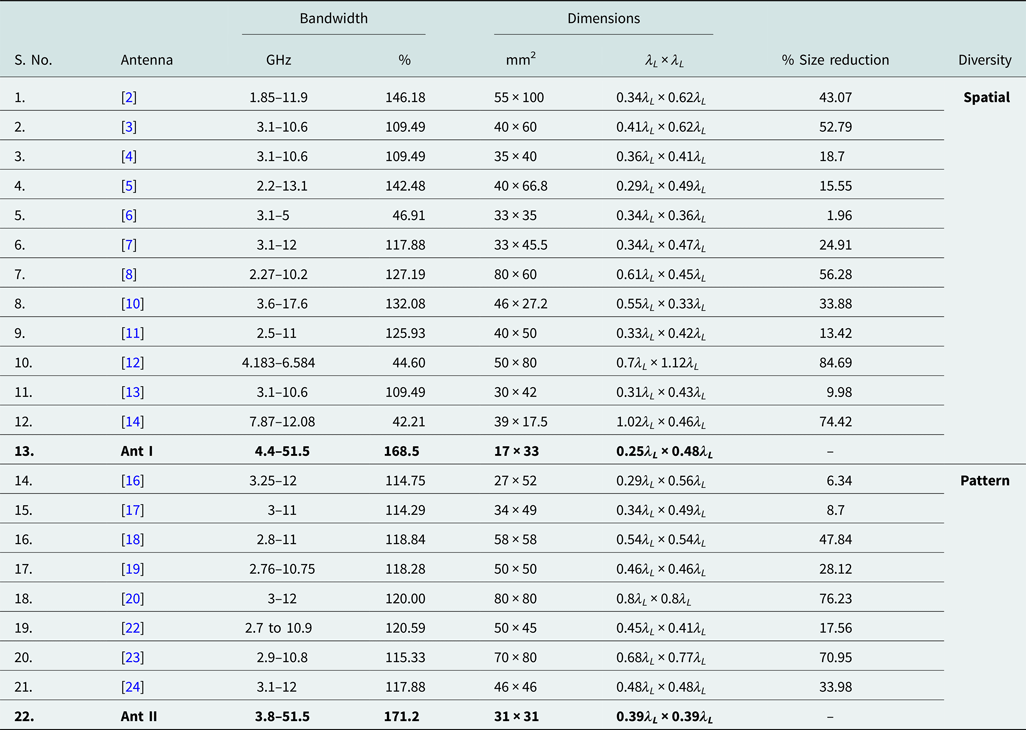
Table 2 presents that for spatial diversity configuration, a size reduction up to 85% is achieved over previous structures with a fractional bandwidth of ~169%. In case of pattern diversity configuration, a size reduction of ~76% is achieved with a fractional bandwidth of 171%.
Comparison of two antenna configurations with previously reported structures
Conclusion
Two-element spatial and pattern diversity configurations of circular slot-loaded feather-shaped super wideband monopole antenna are investigated for MIMO applications. By using an inter-element separation of λ/10 in spatial configuration, isolation is improved. In pattern diversity configuration, a diagonal metallic strip is inserted between two orthogonal elements for inter-element isolation improvement. Both configurations have good diversity performance parameters such as ECC, DG, and channel capacity loss. These values of diversity performance parameters, wide bandwidth, and miniaturized dimensions prove the suitability of designed antenna configurations for SWB MIMO applications.
 Sarthak Singhal was born in Gwalior (M.P.) in 1987. He received his B.E. degree in Electronics & Telecommunication Engineering from SGSITS, Indore (M.P.) in 2010, the M.Tech. degree in Microwave Engineering, and the Ph.D. degree from I.I.T. (B.H.U) Varanasi in 2012 and 2015, respectively. His research areas are microstrip antenna and UWB antennas. He worked as an Assistant Professor at Amity School of Engineering & Technology (ASET), Bijwasan, New Delhi; Amity University, Gwalior, Madhya Pradesh; and Madhav Institute of Technology & Science, Gwalior, Madhya Pradesh. Presently, he is working as an Assistant Professor at Malaviya National Institute of Technology, Jaipur since February 2019. He has published over 40 research papers in journals, 10 in conference proceedings, and two books titled “Design and Analysis of Shorted Gap Coupled Patch Antenna” and “Design and Analysis of Ultra Wideband Microstrip Antennas” from LAP LAMBERT Academic Publishing House.