I. INTRODUCTION
Nanocrystalline materials have unique mechanical properties, such as extremely high strength, great hardness, and excellent wear resistance, which have attracted the attention of intensive researchers. However nanocrystalline materials exhibit very low ductility which limits their applications. In this context, many researchers studied the ductility of nanocrystalline materials through experiments, molecular dynamics (MD) simulations, and theories. In the experiment, by observing the deformation behavior of gold and silicon films, AifantisReference Aifantis1 found the lack of dislocation activity and nanovoid nucleation at a junction of triple nanograin boundaries and nanovoid coalescence, resulting in material failure. Therefore, the nucleation, growth, and coalescence of nanovoids will cause the material ductile failure.Reference Lubarda, Schneider, Kalantar, Remington and Meyers2–Reference Jing, Yuan, Shivpuri, Xu, Zhang, Shan and Guo6 Due to the growth of nanovoids before the coalescence, the study of nanovoid growth is essential for improving the properties of nanocrystalline materials. Fang et al.Reference Fang, Li, Tao and Lu7 successfully prepared the nanocrystalline sample with outstanding ductility dominated by grain boundary migration. The experimental result of Liu et al.Reference Liu, Mao, Wang, Han and Zhang8 demonstrated that nanograin rotation is a plastic deformation mechanism which increases the material strength and ductility and supported the comprehension of the nucleation, growth as well as mobilization of disclinations caused by nanograin rotation. The growth of nanograin driven by stress makes nanocrystalline materials with good mechanical properties.Reference Li and Chen9 The above analysis shows that grain rotation and nanovoids play important role in nanocrystalline materials.
In addition, MD simulations and theories have also been used to reveal and understand the influence of nanovoids’ growth and nanograins’ rotation on the properties of nanocrystalline materials. Simulation results reported by Szlufarska et al.Reference Szlufarska, Nakano and Vashishta10 shown that the crossover between grain boundary sliding, nanograin rotation, and intergranular dislocation is important to improve the mechanical properties of nanoceramic materials. MD simulation shown that once the dislocation is emitted from the nanovoid, the void grows one Burgers vector.Reference Rudd11 The effect of strain rateReference Zhao, Gudem Ringdalen, Wu, He and Zhang12 and lattice orientationReference Wang, Yue, Wen, Zhang and Liu13 and initial nanovoids geometryReference Xu, Su, Chen and Li14 and location of nanovoids (intergranular and intragranular nanovoids)Reference Jing, Yuan, Shivpuri, Xu, Zhang, Shan and Guo6 on the growth of nanovoids has been studied by MD simulation. Goyat et al.Reference Goyat, Verma and Garg15 explored the effect of the functionally graded material layer on the concentration stress of holes by the finite element method.
Theory is an indispensable means to study the properties of materials. Based on the existing theory of dislocation, Stevens et al.Reference Stevens, Davison and Warren16 established a kinematic mechanical model to explain the growth of voids in high-purity monocrystal aluminum. Using the dislocation emission theory, Lubarda et al.Reference Lubarda, Schneider, Kalantar, Remington and Meyers2 established the critical stress model of the first dislocation released from the void surface. Then LubardaReference Lubarda17 improved the model and analyzed the direction of dislocation emission from the nanovoid surface under different combined loadings. Ovid’ko and his teamReference Ovid’ko and Sheinerman18,Reference Bobylev, Mukherjee and Ovid’ko19 demonstrated the cooperative behavior of rotational deformation and nanograin boundary sliding through energy theory analysis. Subsequently, the theoretical study of Morozov et al.Reference Morozov, Ovid’ko, Sheinerman and Aifantis20 shown that the grain rotation releases the high stress at the crack tip and is therefore seen as a toughening mechanism. Li et al.Reference Li and Chen9,Reference Li, Soh and Chen21 proposed a new toughening mechanism of shear-coupled nanograin boundaries coupled with nanograin rotation to study crack blunting in nanocrystalline metals. By using the complex function, Fang et al.Reference Fang, Li and Liu22 determined the explicit solution of the image force which applies on the edge dislocation. And then, he and his teamReference Zhao, Fang and Liu23 studied the influence of nanograin boundary sliding on the growth of the nanovoid. The analysis results clearly shown that the high stress nearby the nanovoid can be released by the boundary sliding of the nanograin, which leads to slower growth of the nanovoid. Wang et al.Reference Wang, Zhou, Liu, Zhang, Wang and Xing4 proposed a model for the growth of the nanovoid at the triple junction under the action of equal biaxial remote stress, calculated the critical stress of the first dislocation emission considering the surface effect of nanoscale void, and analyzed the maximum number of dislocations released from the nanoscale void surface. In another paper, Wang et al.Reference Wang, Zhou, Zhang, Liu and Dong24 proposed a model to explore the influence of accommodated nanograin boundary sliding on triple junction nanovoid nucleation in nanocrystalline materials. Then he and his coworkersReference Zhang, Zhou, Wang, Wang and Dong5,Reference He, Zhou and Liu25 came up with a model of the influence of nanotwin boundaries on the nanovoid growth, which revealed that the smaller the twin spacing is, the slower the growth of the nanovoid can be. They also suggested another theoretical model of the influence of the finest nanograin at the triple junction on the nanovoid growth and concluded that finest nanograin could obviously hinder the growth of nanovoid. Yang et al.Reference Yang and Gao26 studied the influence of the functionally gradient layer on the concentration stress of holes by the method of complex variable function. Through the experimental, simulational, and theoretical summaries, it is found that the grain rotation can be served as a toughening mechanism, but the growth of the nanovoid can be considered as a damage mechanism in nanocrystalline materials. However, up to now, researchers have not paid much attention to the combined effect of two mechanisms on the mechanical properties of materials. Thus it is necessary to understand the comprehensive effect to improve the properties of materials.
To study the influence of grain rotation on the growth of the nanovoid, there are three aspects to be considered. The first aspect is that the nanovoid has the high surface-to-volume, which can produce important traction on the nanovoid surface, thus the effect of the nanovoid surface should not be ignored in detail calculation.Reference Goudarzi, Avazmohammadi and Naghdabadi27,Reference Zhang, Wang and Chen28 The second aspect is that when the size of the grain decreases to nanometer scale, the boundary of the nanograin can effectively suppress dislocation emission.Reference Shi and Zikry29 And finally, the effect of the grain rotation on the dislocation emission from the surface of the nanovoid should also be considered in detail.
In this paper, we consider the grain rotation which will form immobile disclinations quadrupole at the triple junction.Reference Morozov, Ovid’ko, Sheinerman and Aifantis20 The object of this paper is to quantificationally analyze the critical stress of the nanovoid growth and its dependence on the parameters such as the nanovoid radius, surface effects, nucleation radius, dislocation emission angle, the relative distance between rotation grain and the center of nanovoid, the size of rotation grain, the direction angle of the rotation grain boundary, and the rotation coefficient which indicate the rotational process. Finally, we study the combined effect of grain boundary and rotation deformation on the nanovoid growth.
II. MECHANICAL MODEL
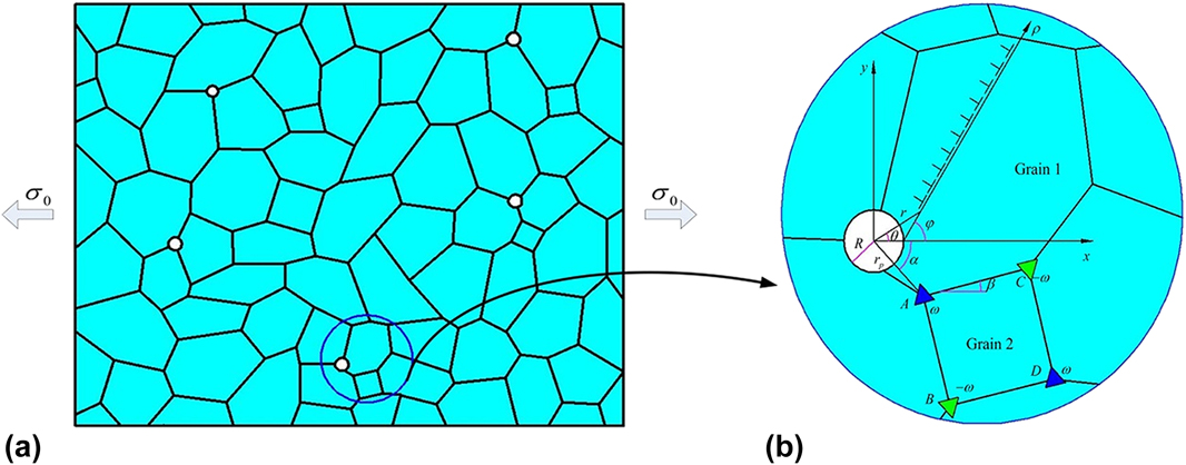
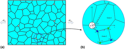
It is difficult to explain the basic mechanical behavior of nanocrystalline materials of the complex microstructure. Therefore, we first consider that the nanocrystalline specimen containing rotational nanograins and nanovoids is subjected to uniaxial far field stress σ0. The interaction between nanovoids is neglected and these nanovoids are located at the triple junctions. Second, we assume that the nanocrystalline specimen is an elastically isotropic homogeneous material with Poisson’s ratio ν and the shear modulus μ. Finally, the imperfect structure is assumed to be unchanged in the z axis so that the mechanical model can be simplified from three dimensions to two dimensional x–y plane. Based on the above assumptions, the model for studying the current problem is shown in Fig. 1.
Rotational grain near the nanovoid in a tensile nanocrystalline solids: (a) general view and (b) the magnified inset highlights a disclination quadrupole and dislocations near the nanovoid.

A. Stress field near a circular nanovoid
A diagram of a circular nanovoid with radius R in an infinite plane is shown in Fig. 1. We do not consider the body forces. Two polar coordinate systems (r, θ) and (ρ, φ) are used in the process of calculation. Based on the geometric structure in Fig. 1, the relationship of coordinates can be obtained:
 $$\varphi = \arccos {{{r^2} - {R^2} - {\rho ^2}} \over {2 \cdot R}}\quad ,$$
 $$\theta = \arctan {{\rho \cdot \sin \varphi } \over {R + \rho \cdot \cos \varphi }}\quad .$$
The Gurtin–Murdoch model considering the surface effect was developed, and the surface effect can be influenced by residual stress and free surface energy. Therefore, for the nanovoid surface, the constitutive equation and the equilibrium equation are
 $$\sigma _{\alpha \beta }^{\rm{s}} = {\tau ^{\rm{s}}}{\delta _{\alpha \beta }} + 2\left( {{\mu ^{\rm{s}}} - {\tau ^{\rm{s}}}} \right){\varepsilon _{\alpha \beta }} + \left( {{\lambda ^{\rm{s}}} + {\tau ^{\rm{s}}}} \right){\varepsilon _{\gamma \gamma }}{\delta _{\alpha \beta }}\quad ,$$
 $$\sigma _{ij}^{\rm{b}}{{\bi{n}}_i}{{\bi{n}}_j} - \sigma _{\alpha \beta }^{\rm{s}}{{\bi{k}}_{\boldalpha \boldbeta }} = 0\quad ,$$
where superscripts b and s, respectively, represent the matrix and surface of the nanovoid; εαβ and σαβ denote the strain and stress components, respectively; ni is the nanovoid surface normal vector; kαβ is the curvature tensor of the surface; δαβ denotes the Kronecker delta; λs and μs are the Lamé constants of the surface; τs represents the residual surface stress under unstrained condition.
For the matrix, the constitutive equation and the equilibrium equation can be, respectively, expressed as
 $$\sigma _{ij}^{\rm{b}} = \lambda {\varepsilon _{kk}}{\delta _{ij}} + 2\mu {\varepsilon _{ij}}\quad ,$$
 $$\sigma _{ij,j}^{\rm{b}} = 0\quad ,$$
where λ and μ are the matrix Lamé constants.
As for plane strain problem, the displacement and the stress component near the nanovoid are expressed by two Kolosoff–Mushelishvili functionsReference Li and Chen30 Φ(z) and Ψ(z):
 $${\sigma _{11}} + {\sigma _{22}} = 4{\mathop{\rm Re}\nolimits} \Phi '\left( z \right)\quad ,$$
 $${\sigma _{22}} - {\sigma _{11}} + i{\sigma _{12}} = 2\left[ {\bar{z}\Phi ''\left( z \right) + \Psi '\left( z \right)} \right]\quad ,$$
 $$2\mu \left( {{u_1} + i{u_2}} \right) = k\Phi \left( z \right) - z\overline {\Phi '\left( z \right)} - \overline {\Psi \left( z \right)} \quad ,$$
 $${\sigma _{{\rm{rr}}}} + {\sigma _{{\rm{\theta \theta }}}} = 4{\mathop{\rm Re}\nolimits} \Phi '\left( z \right)\quad ,$$
 $${\sigma _{{\rm{rr}}}} + i{\sigma _{{\rm{\theta \theta }}}} = \Phi '\left( z \right) + \overline {\Phi '\left( z \right)} + {{\rm{e}}^{2i{\rm{\theta }}}}\left[ {\bar{z}\Phi ''\left( z \right) + \Psi '\left( z \right)} \right]\quad ,$$
 $$2\mu \left( {{u_{\rm{r}}} + i{u_{\rm{\theta }}}} \right) = {{\rm{e}}^{ - i{\rm{\theta }}}}\left[ {k\Phi \left( z \right) - z\overline {\Phi '\left( z \right)} - \overline {\Psi \left( z \right)} } \right]\quad ,$$
where σij and u i are, respectively, stress components and displacement components; z = R + ρeiφ and k = 3 − 4ν for the plane strain problem.
To solve this equation, we expand Φ(z) and Ψ(z) into a power series form. We can obtain
 $$\Phi \left( z \right) = \sum\limits_{{k_1} = 0}^\infty {A{}_{{k_1}}{z^{ - {k_1}}}} \quad ,$$
 $$\Psi \left( z \right) = \sum\limits_{{k_1} = 0}^\infty {{B_{{k_1}}}{z^{ - {k_1}}}} \quad .$$
Substituting Eqs. (13) and (14) into Eqs. (7) and (8), and considering boundary condition, we can get the following results
 $${A_0} = {{{\sigma _{11}}} \over 4}R,\;{B_0} = - {{{\sigma _{11}}} \over 2}R\quad ,$$
where σ11 is the far field stress and σ11 = σ0.
Combining Eqs. (3) and (4) with (7)–(15), we can determine the coefficient of Φ(z) and Ψ(z):
 $${A_1} = {{ - \left( {1 + 2{\Lambda _1}} \right){B_0}} \over {1 + 4{\Lambda _1} + {\Lambda _1}{\Lambda _2}}},\;{A_k} = 0\left( {n \ge 2} \right)\quad ,$$
 $${B_1} = {{{\tau ^{\rm{s}}} + 2{A_0}\left( {{\Lambda _1}{\Lambda _2} - 1} \right)} \over {1 + 2{\Lambda _1}}},\;{B_2} = 0\quad ,$$
 $${B_3} = {{{B_0}\left( {{\Lambda _1}{\Lambda _2} - 1} \right)} \over {1 + 4{\Lambda _1} + {\Lambda _1}{\Lambda _2}}},\;{B_3} = {{{B_0}\left( {{\Lambda _1}{\Lambda _2} - 1} \right)} \over {1 + 4{\Lambda _1} + {\Lambda _1}{\Lambda _2}}}\quad ,$$
where
 $${\Lambda _1} = {{2{\mu ^{\rm{s}}} + {\lambda ^{\rm{s}}} - {\tau ^{\rm{s}}}} \over {4\mu R}},\;{\Lambda _2} = {{2\mu } \over {\lambda + \mu }}\quad .$$
By substituting Eqs. (16) and (17) into Eqs. (7) and (12), we can get the expression of the stress field in the neighborhood of a nanovoid
 $${\sigma _{{\rm{rr}}}} = {{{\sigma _{11}}} \over 2} + {{2{\tau ^{\rm{s}}}R + {\sigma _{11}}\left( {{\Lambda _1}{\Lambda _2} - 1} \right){R^2}} \over {2\left( {1 + 2{\Lambda _1}} \right){r^2}}} + \left[ {{{3\left( {{\Lambda _1}{\Lambda _2} - 1} \right){R^4}} \over {2\left( {1 + 4{\Lambda _1} + {\Lambda _1}{\Lambda _2}} \right){r^4}}} + \left. {{{2\left( {1 + 2{\Lambda _1}} \right){R^2}} \over {\left( {1 + 4{\Lambda _1} + {\Lambda _1}{\Lambda _2}} \right){r^2}}} - {1 \over 2}} \right]{\sigma _{11}}\cos \left( {2\theta } \right)} \right.\quad ,$$
 $${\sigma _{{\rm{r\theta }}}} = \left[ {{{3\left( {{\Lambda _1}{\Lambda _2} - 1} \right){R^4}} \over {2\left( {1 + 4{\Lambda _1} + {\Lambda _1}{\Lambda _2}} \right){r^4}}} + {{\left( {1 + 2{\Lambda _1}} \right){R^2}} \over {\left( {1 + 4{\Lambda _1} + {\Lambda _1}{\Lambda _2}} \right){r^2}}} + {1 \over 2}} \right]{\sigma _{11}}\sin \left( {2{\rm{\theta }}} \right)\quad ,$$
 $${\sigma _{\theta \theta }} = {{{\sigma _{11}}} \over 2} - {{2{\tau ^{\rm{s}}}R + {\sigma _{11}}\left( {{\Lambda _1}{\Lambda _2} - 1} \right){R^2}} \over {2\left( {1 + 2{\Lambda _1}} \right){r^2}}} - \left[ {{{3\left( {{\Lambda _1}{\Lambda _2} - 1} \right){R^4}} \over {2\left( {1 + 4{\Lambda _1} + {\Lambda _1}{\Lambda _2}} \right){r^4}}} - {1 \over 2}} \right]{\sigma _{11}}\cos \left( {2\theta } \right)\quad .$$
B. Stress generated by rotational grain
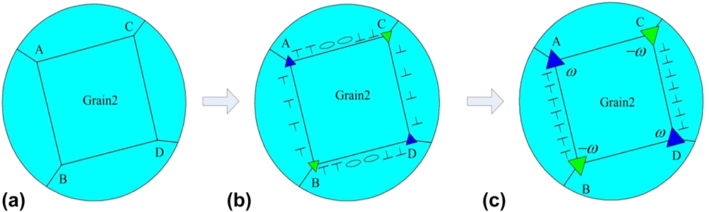
Within our model, when a nanocrystalline specimen is subjected to far-filed stress, the rotational deformation in the nanograin ABCD occurs through the formation of immobile disclination quadrupole represented by triangular symbols at junctions, as shown in Figs. 2(a)–2(c). By nanograin boundary sliding along grain boundaries AC and BD and diffusion-controlled climb of grain boundary dislocations along grain boundaries AB and CD, the initiation and development of the quadrupole at the junctions of quadrate Grain2 is realized in deformed materials, as shown in Figs. 2(a)–2(c). Following the concept on local shear events–shear transformations of local atomic clusters-as carriers of plastic flow in grain boundaries in metals,Reference Padmanabhan and Gleiter31 we will assume that the boundary sliding along AC and BD can be carried by local shear events. The grain boundary sliding can cause the boundary dislocation formation at junctions of the nanograin.Reference Bobylev, Gutkin and Ovid’ko32,Reference Bobylev, Mukherjee and Ovid’ko33 Dislocation climbs controlled by diffusion along AB and CD can cause grain rotation, at the same time, an immobile disclination quadrupole form at endpoints A, B, C, and D, as shown in the Figs. 2(a)–2(c).
Geometry of crystal lattice rotations of Grain2 in nanocrystalline materials. (a) Initial state containing a square nanograin ABCD. (b) Rotational deformation occurs in a nanograin through the formation of immobile disclinations (triangles) whose strengths gradually increase during the formation process conducted by grain boundary dislocation slip and climb. (c) Final state containing finite grain boundary dislocation walls, AB and CD, which create elastic stresses effectively approximated as those created by a quadrupole of disclinations located at the nanograin edges A, B, C, and D.

More accurately, when the shear stress is applied to these grain boundaries, dislocations nucleated at grain boundaries AC and BD can carry grain boundary sliding, as shown in Fig. 2(b). In parallel with dislocation nucleations, dislocation climbs over grain boundaries AB and CD can be provided by diffusion. The diffusion is promoted by the stresses arising during boundary sliding, as shown in Figs. 2(b) and 2(c). In consequence, two boundary dislocation walls appear at the grain boundaries AB and CD and have opposite signs, as shown in Figs. 2(b) and 2(c). The arising of dislocation walls finally causes grain deformation. In addition, compared to the initial state, the boundary dislocation walls not only produce stresses but also provide extra tilt misorientation of nanograin boundaries AB and CD,Reference Feng, Fang, Zhang and Liu34 as schematically shown in Figs. 2(b) and 2(c). Based on the defect theory in solids,Reference Fressengeas, Taupin and Capolungo35 a disclination quadrupole located at nanograin boundary junction A, B, C and D, as shown in Figs. 2(b) and 2(c), create elastic stresses approximately is equal to those created by finite grain boundary dislocation walls forming at boundaries AB and CD. It is noted that the magnitudes of a disclination quadrupole strength will gradually enhance with the increase of dislocation density of nanograin boundaries AB and CD.Reference Ovid’ko and Sheinerman18,Reference Feng, Fang, Zhang and Liu34
The expression of stress σω generated by a disclination quadrupole can be written as
 $${\sigma _\omega } = \left( {{\sigma _{yy}} - {\sigma _{xx}}} \right)\sin \;\varphi \;\cos \;\varphi + {\sigma _{xy}}\cos \;2\varphi \quad ,$$
where the stress σω acts on the dislocation on the slip plane. Stress field components σxx, σyy, and σxy, in the Cartesian coordinates, can be expressed as σxx = Re(2Φω(z) − h), σyy = Re(2Φω(z) + h), σxy = Im(h), where  $h = \bar{z}{\Phi '_{\rm{\omega }}}\left( z \right) + {\Psi _{\rm{\omega }}}\left( z \right)$. The complex functions Φω(z) and Ψω(z) arising from a disclination quadrupole can be obtained asReference Zhao, Fang and Liu23
 $${\Phi _\omega }\left( z \right) = \sum\limits_{j = 1}^2 {{{\left( { - 1} \right)}^{j + 1}}} \left( {{{D\omega } \over 2}\ln {{z - {z_{pj}}} \over {z - {z_{nj}}}} + \sum\limits_{k = 0}^\infty {{A_{kj}}{z^{ - k}}} } \right)\quad ,$$
 $${\Psi _\omega }\left( z \right) = \sum\limits_{j = 1}^2 {{{\left( { - 1} \right)}^{j + 1}}} \left( {{{{R^2}} \over {{z^2}}}{{D\omega } \over 2}\left( {{z \over {z - {z_{nj}}}} - {z \over {z - {z_{pj}}}} <$$><$$>- {{\left( {\overline {{z_{pj}}} - \overline {z_{pj}^*} } \right)z} / {\left( {z - {z_{pj}}} \right)\overline {z_{pj}^*} }}} } \,\left. { + {{\left( {\overline {{z_{nj}}} - \overline {z_{nj}^*} } \right)z} / {\left( {z - {z_{nj}}} \right)\overline {z_{nj}^*} }} <$$><$$>+ {{\left( {\overline {z_{nj}^*} - \overline {z_{pj}^*} } \right)z} / {{R^2}}} + \ln {{{z_{pj}}} \over {{z_{nj}}}}} \right\bigg)\left. { + \sum\limits_{k = 0}^\infty {{{{R^2}} \over {{z^{k + 2}}}}\left( {\left( {k + 1} \right){A_{kj}} + {B_{kj}}{R^{2k}}} \right)} } \right)\quad ,$$
where D = µ/(2π(1−ν)), μ represents the shear modulus, and ν is Poisson’s ratio of the matrix. z = R + ρeiφ is the dislocation coordinate.  $z_{pj}^* = {{{R^2}} / {\overline {{z_{pj}}} }}$,
 $z_{nj}^* = {{{R^2}} / {\overline {{z_{nj}}} }}$. The coordinates corresponding to the wedge disclination quadrupole at junctions A, B, C, and D are z p1 = r peiα, z p2 = r peiα + dei(β−π/2), z n1 = r peiα + deiβ, z n2 = r peiα + dei(2β−π/2). ω is the rotation strength which can be expressed by the rotation coefficient k and ultimate rotation strength η (as the grain begins to rotate, the strength of the quadrupole of disclinations increases from 0. Finally when the grain stops rotating, the disclination quadrupole strength reaches its maximum value, the maximum value is called the ultimate rotation strength.): ω = k 2η to understand the effect of the rotational process on the nanovoid growth.
To facilitate the calculation and ensure the accuracy of the calculation, we retain the constant term and the first term of the power series.
 $${A_{0j}} = {{\left( {1 - a - b} \right){{D\omega } / {2 \cdot \ln \left( {{{\overline {{z_{pj}}} } / {\overline {{z_{nj}}} }}} \right) - \left( {a + b} \right){{D\omega } / 2} \cdot \ln \left( {{{{z_{pj}}} / {{z_{nj}}}}} \right) - {{{\tau ^{\rm{s}}}} / R}}}} \over {a + b + \left( {1 + a} \right){{\left( {1 - a - b} \right)} / a}}}\quad ,$$
 $${A_{1j}} = 0\quad ,$$
where a = (2μs + λs − τs)/4Rμ, b = (2μs + λs − τs)/2R(λ + µ).
Substituting Eqs. (22)–(24) into Eq. (21), the stress σω acting on dislocation can be calculated.
C. Critical stress of the first dislocation emission
In the laser shock experiment, LubardaReference Lubarda, Schneider, Kalantar, Remington and Meyers2 suggested the mechanism of void growth based on the dislocation emitted from the void surface, which has been confirmed by molecular simulation calculations.Reference Traiviratana, Bringa, Benson and Meyers36 The brief description of the menchanism is that when a dislocation is emitted and departed from the nanoscale void surface, the radius of void increases a Burgers vector, and the radius of the nanovoid is gradually increasing when the dislocation continues to emit.
To determine the critical stress of the first dislocation emitted from the nanoscale void surface, we need to identify the stress on the dislocation. The first dislocation is affected by three stresses: the first stress σa arises from the far-filed stress, which can drive the dislocation away from the nanovoid surface; the second stress σω is produced by grain rotation; the third stress σi is the image stress caused by the attraction of the free surface of the nanovoid.Reference Lubarda17 Therefore, the total stress σtot acting the first dislocation can be written as
 $${\sigma _{{\rm{tot}}}} = {\sigma _{\rm{a}}} + {\sigma _\omega } + {\sigma _i}\quad ,$$
where σa and σi are expressed as
 $${\sigma _{\rm{a}}} = {1 \over 2}\left( {{\sigma _{\theta \theta }} - {\sigma _{{\rm{rr}}}}} \right)\sin 2\left( {\varphi - \theta } \right) + {\sigma _{{\rm{r}}\theta }}\cos 2\left( {\varphi - \theta } \right)\quad ,$$
 $${\sigma _i} = {{Gb\cos \left( {\varphi - \theta } \right){R^2}} \over {2\pi \left( {1 - \nu } \right){r^3}}}\left( {2{{{r^2} - {R^2}} \over {{r^2}}} - {{{r^4}} \over {{R^2}\left( {{r^2} - {R^2}} \right)}}} \right)\quad ,$$
Substituting Eqs. (21), (26), and (27) into Eq. (25), and letting σtot = 0, we can obtain the expression of the critical stress σcr.
D. Growth criterion of the nanovoid
In this section, the effect of the boundary of Grain1 on the growth of the nanovoid is described theoretically. To understand the influence of the grain boundary, we suppose that dislocations can be emitted and the subsequent dislocations are located on the same slip surface as the first dislocation. In nanocrystalline materials, grain boundaries are often seen as barriers to dislocation movement. Therefore, we suggest that when the first dislocation is emitted and moved on the slip plane and finally stopped at the grain boundary, it can produce an impediment stress which makes the further dislocation emission and movement more difficult.
Therefore, there are four stresses acting on new dislocations. Beside three stresses σa, σω, and σi, we consider the stress of the effect of dislocation emitted previously on the further dislocation. The effect of the emitted dislocation on the new dislocation is called the back stress.Reference Wang, Zhou, Zhang, Liu and Dong24 The subsequent dislocations will reach an equilibrium position under the influence of four stresses. For a given grain size and applied stress, there is a maximum number of dislocations on the slip plane. To obtain the maximum dislocation number, the criterion for the first dislocation emission is that the effective stress σe(ρ1, φ) at the nucleation radius ρc of the dislocation is greater than zero.Reference Ovid’ko and Sheinerman37 The effective stress can be expressed as
 $${\left. {{\sigma _{\rm{e}}}\left( {{\rho _1},\varphi } \right) = {\sigma _{\rm{a}}}\left( {{\rho _1},\varphi } \right) + {\sigma _\omega }\left( {{\rho _1},\varphi } \right) + {\sigma _i}\left( {{\rho _1},\varphi } \right)} \right|_{{\rho _1} = {\rho _{\rm{c}}}}} > 0\quad ,$$
where (ρ1, φ) is the coordinate of the first dislocation. σa(ρ1, φ) is the driving stress acting on the 1st dislocation, σω(ρ1, φ) is created by the rotational grain, and σi(ρ1, φ) is generated from the free void surface.
Similarly, the effective stress of the (N + 1)th dislocation emission is
 $${\left. {{\sigma _{\rm{e}}}\left( {{\rho _{N + 1}},\varphi } \right) = {\sigma _{\rm{a}}}\left( {{\rho _{N + 1}},\varphi } \right) + {\sigma _\omega }\left( {{\rho _{N + 1}},\varphi } \right) <$$><$$>+ {\sigma _i}\left( {{\rho _{N + 1}},\varphi } \right){\rm{ + }}\sum\limits_{i = 1}^N {{\sigma _{\rm{d}}}\left( {{\rho _{N + 1}},{\rho _i},\varphi } \right)} } \right|_{{\rho _{N + 1}} = {\rho _{\rm{c}}}}} > 0\quad ,$$
where (ρN+1, φ) is the coordinate of (N + 1) dislocation. σd(ρN+1, ρi, φ) expresses the stress generated through the ith dislocation at the point (ρN+1, φ).
According to the result of the Ref. Reference Wang, Zhou, Liu, Zhang, Wang and Xing4, the stress σd(ρN+1, ρi, φ) can be obtained as
 $${\sigma _{\rm{d}}}\left( {{\rho _{N + 1}},{\rho _i},\varphi } \right) = \left( {\sigma _{yy}^{\rm{d}} - \sigma _{xx}^{\rm{d}}} \right)\sin \varphi \cos \varphi + \sigma _{xy}^{\rm{d}}\left( {2\varphi } \right)\quad ,$$
where the stress  $\sigma _{yy}^{\rm{d}}$,
 $\sigma _{xx}^{\rm{d}}$, and
 $\sigma _{xy}^{\rm{d}}$ can be expressed as
 $\sigma _{yy}^{\rm{d}} = {\mathop{\rm Re}\nolimits} \left( g \right)$,
 $\sigma _{xy}^{\rm{d}} = - {\mathop{\rm Im}\nolimits} \left( g \right)$,
 $\sigma _{xx}^{\rm{d}} = {\mathop{\rm Re}\nolimits} \left( {4\psi ' - g} \right)$, where
 $g = \psi ' + \overline {\xi '} + \left( {z - \bar{z}} \right)\overline {\psi '}$. ψ and ξ are two complex functions of the complex variable z = x + iy and i = −1. The quantities ψ′ and
 $\overline {\xi '}$ for a dislocation located at the point z = x i + iy i areReference Ovid’ko and Sheinerman37
 $$\psi ' = A\left( {{1 \over {z - {z_i}}}\left( {\sqrt {{{{z_i}} / z}} + 1} \right) + {1 \over {z - \overline {{z_i}} }}\left( {\sqrt {{{\overline {{z_i}} } / z}} - 1} \right)} \right) + {{\overline A \left( {{z_i} - \overline {{z_i}} } \right)} \over {2{{\left( {z - \overline {{z_i}} } \right)}^2}}}\left( {\sqrt {{{\overline {{z_i}} } / z}} + \sqrt {{z / {\overline {{z_i}} }}} - 2} \right)\quad ,$$
 $$\overline {\xi '} = A\left( {{1 \over {\bar{z} - {z_i}}}\left( {\sqrt {{{{z_i}} / {\overline z }}} - 1} \right) + {1 \over {\bar{z} - \overline {{z_i}} }}\left( {\sqrt {{{\overline {{z_i}} } / {\overline z }}} + 1} \right)} \right) + {{\bar{A}\left( {{z_i} - \overline {{z_i}} } \right)} \over {2{{\left( {\bar{z} - \overline {{z_i}} } \right)}^2}}}\left( {\sqrt {{{\overline {{z_i}} } / {\bar{z}}}} + \sqrt {{{\bar{z}} / {\overline {{z_i}} }}} + 2} \right)\quad ,$$
where A = G(b cos φ + ib sin φ)/(8πi(1 − ν)), z i = R + ρieiφ.
Substituting Eqs. 31 and 32 into Eq. (30), the stress σd(ρN+1, ρi, φ) expression can be obtained. For simplicity, we suggest that the emitted dislocations distribute uniformly along the same slip direction.
It should be noted that the criterion (29) is not sufficient and necessary condition, but a necessary condition. Thus we first judge the criterion (28) of the leading dislocation emitted from the void surface. If it is valid, we assume that the leading dislocation can be released from the nanovoid surface and stops at a nanograin boundary. Then, we verify the criterion (29) which is suitable for use on the second and subsequent dislocation emission. If this criterion (29) is valid, we can determine the equilibrium position of the second and subsequent dislocation. When the effective stress of Eq. (29) is less than or equal to zero, this procedure ends and finally we can obtain the maximum number of the emitted dislocations.
III. NUMERICAL RESULTS AND DISCUSSION
In this section, we will quantificationally illustrate the influence of grain rotation on nanovoid growth. In doing so, the parameters of nanocrystalline material Al can be used to calculate: the matrix Lamé constants λ = 58.17 GPa, μ = 26.13 GPa, Poisson’s ratio ν = 0.345, Burgers vector b = 0.255 nm, the nanovoid surface Lamé constants λs = 3.4939 N/m, μs = −5.4251 N/m, and residual surface stress τs = 0.5689 N/m for the Al[100] surface and λs = 6.8511 N/m, μs = −0.3760 N/m and τs = 0.9108 N/m for the Al[111] surface. To distinguish nanocrystalline Grain1 from Grain2 in calculation, d1 and d2, respectively, denoted the size of Grain1 and Grain2.
A. Influence of the nanovoid radius R on the critical stress
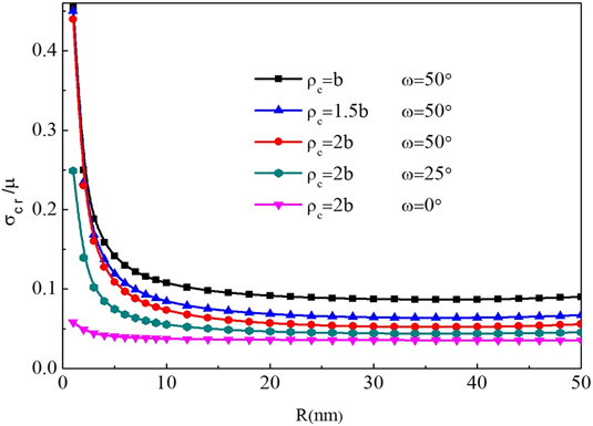
The normalized critical stress σcr/μ versus the nanovoid radius R is plotted in Fig. 3 with different dislocation nucleation radii and rotational strengths. The other parameters are taken as φ = π/3,Reference Wang, Zhou, Zhang, Liu and Dong38 r p = 80 nm, d2 = 10 nm, β = π/6, α = −10°, λs = 0, μs = 0, and τs = 0. The results show that the normalized critical stress will decrease when the radius of nanovoid increases. For the rotation strength ω = 0° that indicates without special rotational deformation, the result in Fig. 3 agrees very well with the analytical result given by Lubarda.Reference Lubarda17 When the radius of the nanovoid is greater than 20 nm, the normalized critical stress tends to be stable. It is also noted that when the radius is less than 2 nm, the results are insignificant because the external stress required is too high. For selected material parameters ρc, the greater the dislocation nucleation radius is, the lower the critical stress to satisfy the emission of first or leading dislocation will be. When the rotational deformation occurs in the nanocrystalline material, the critical stress corresponding to rotational strength ω = 50° is higher than that corresponding to rotational strength ω = 25° and ω = 0°. In addition, we also find that the critical stress at rotational strength ω = 25° is higher than that at rotational strength ω = 0°. This result reveals that the rotational deformation effectively releases the concentrated stresses near the nanovoid, which makes it more difficult for the dislocations to emit from the surface of the nanovoid, thus hindering the growth of the nanovoid.
Normalized critical stress σcr/μ versus the nanovoid radius R with different dislocation nucleation radii and rotational strengths for φ = π/3, r p = 80 nm, d2 = 10 nm, β = π/6, α = −10°, and λs = μs = τs = 0.

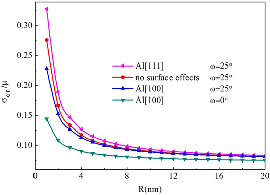
Figure 4 shows the dependence of the normalized critical stress σcr/μ on the nanovoid radius R considering different surface effects and rotational strengths. The other geometric parameters are selected as φ = π/3, r p = 80 nm, d2 = 10 nm, β = π/6, α = −10°, and ρc = b. The results indicate that the critical stress decreases with the increase of nanovoid radius. When the radius of nanovoid exceeds 18 nm, the influence of the nanovoid surface on the critical stress will be the same. Compared with the critical stress without the surface effect, when the nanovoid radius decreases from 6 to 2 nm [111]([100]) surface effect causes a hardening (softening) effect on the nanovoid surface, thus incerasing (decreasing) the critical stress. It is noteworthy, however, that the critical stress at ω = 25° is bigger than that at ω = 0° for the [100] surface because the increase of rotational strengths can effectively suppress the emission of dislocation. Therefore, the rotation deformation is very important to improve the fracture toughness of the nanocrystalline material. The result is what we expect in nanocrystalline materials.
Normalized critical stress σcr/μ versus the nanovoid radius R with different surface effects and rotational strengths for φ = π/3, r p = 80 nm, d2 = 10 nm, β = π/6, α = −10°, and ρc = b.

B. Influence of the emission angle φ on the critical stress
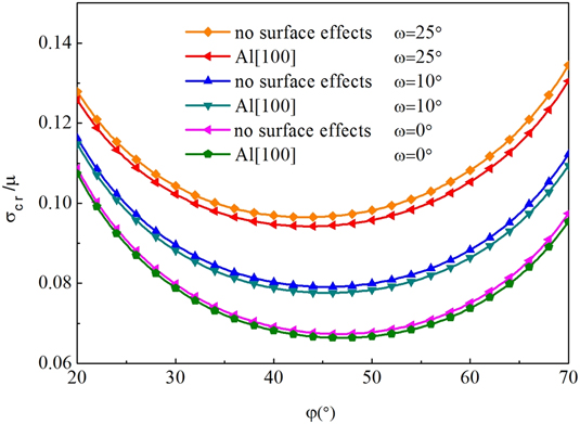
Figure 5 plots the influence of dislocation emission angle φ on the normalized critical stress σcr/μ with different nanovoid surface effects and rotational strengths in deformed nanocrystalline solids. In the course of calculation, the other parameters we use are r p = 80 nm, d2 = 10 nm, β = π/6, α = −10°, ρc = b, and R = 5 nm. It is found that the critical stress first decreases and then increases with the increase of angle of dislocation emission. The minimum critical stresses for leading dislocation emission can enhance with the increase of rotational strengths. The results clearly show that this deformation can prevent dislocation from leaving the nanovoid surface and slow down the nanoscale void growth and improve the ductility of the nanocrystalline material. So the viewpoint that the rotational deformation can be served as a toughening mechanism is consistent with that obtained by Morozov et al.Reference Morozov, Ovid’ko, Sheinerman and Aifantis20 It is shown that the critical stress can be affected by the surface effect under the same condition, but critical dislocation emission angle remains unchanged. [100] surface effect characterized by Lamé constants and residual surface stress decrease the minimum critical stress. This implies that the surface effect of [100] produced by the nanovoid having the high surface-to-volume ratio makes the easy emission of surface dislocation. We can see from Fig. 5 that as the rotational strength increases, the possible critical emission angle will be reduced.
Normalized critical stress σcr/μ versus the emission angle φ with different surface effects and rotational strengths for r p = 80 nm, d2 = 10 nm, β = π/6, α = −10°, ρc = b, and R = 5 nm.

C. Influence of the relative distance r p on the critical stress
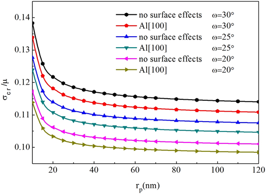
The normalized critical stress σcr/μ with different surface effects and rotational strengths as a function of the relative distance r p can be plotted in Fig. 6. The other geometric parameters are φ = π/3, d2 = 10 nm, β = π/6, α = −10°, ρc = b, and R = 5 nm in the course of calculation. It is observed that the critical stress considering the nanovoid surface effect is lower than that of no surface effect but increasig the strength of rotation can obviously increase the critical stress. This clearly implies that the surface effect can promote the nanovoid growth but deformation of the nanograin in the deformed material can inhibit the growth of the nanovoid. We can also see from Fig. 6 that the critical stress for emission of the first dislocation will decrease when the relative distance r p increases. As the distance is bigger than 100 nm, the value of critical stress tends to be stable. This clearly illustrates that the further the distance between the deformation nanograin and the center of nanovoid is, the smaller the release of the high stress near the nanovoid is. In other words, with the increase of the relative distance, the emission of dislocation is more easily to cause the obvious acceleration of the nanovoid growth.
Normalized critical stress σcr/μ versus the relative distance r p with different surface effects and rotational strengths for φ = π/3, d2 = 10 nm, β = π/6, α = −10°, ρc = b, and R = 5 nm.

D. Influence of the size of deformed nanograin d2 on the critical stress
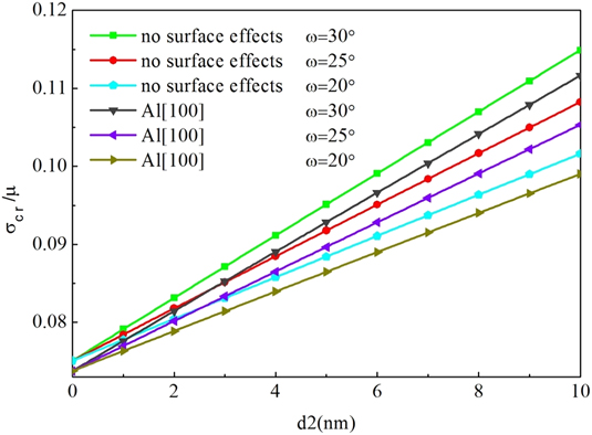
Figure 7 plots the influence of the size of the deformed nanograin on the critical stress considering different surface effects and rotational strengths. The selected parameters are φ = π/3, r p = 80 nm, β = π/6, α = −10°, ρc = b, and R = 5 nm. The results show that the critical stress increases linearly with the increase of the deformed nanograin size. This states that the rotation deformation of large nanograin near the nanovoid releases higher energy than that of the small nanograin, which makes nanovoid growth more difficult. At the same time, when the disclination strengths increase gradually, the effect of the nanograin size on the critical stress can increase obviously in nanocrystalline materials. This illustrates that nanograin deformation plays an important role in inhibiting nanovoid growth. As can be seen from Fig. 7, the surface effect has an influence on the critical stress, and the two slope values are the same under the same rotation strength. Thus, its influence is almost unaffected by the changing nanograin size. This result shows that the nanovoid surface effect should be taken into account in detail calculation.
Normalized critical stress σcr/μ versus the size of deformed nanograin d2 with different surface effects and rotational strengths for φ = π/3, r p = 80 nm, β = π/6, α = −10°, ρc = b, and R = 5 nm.

E. Influence of the process of rotation on the critical stress
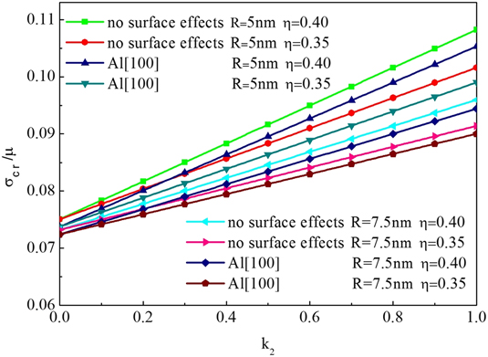
The normalized critical stress σcr/μ with different surface effects and ultimate rotational strengths and nanovoid radius as a function of the rotation coefficient k 2 can be plotted in Fig. 8. The selected parameters of detail calculation are φ = π/3, ρp = 80 nm, β = π/6, α = −10°, ρc = b, and d2 = 10 nm. It can be seen from Fig. 8 that the critical stress linearly increases with the increase of the rotation coefficient. It is shown that the dislocation emission from the nanovoid surface can be obviously controlled by the process of rotation deformation which gradually suppresses the nanovoid growth. In addition, increasing the nanovoid radius and considering the surface effect produce the negative influence on the critical stress. When the rotation coefficient gradually increases, the influence of the nanovoid radius on the critical stress will become greater. It is noted that the bigger the rotational coefficient is, the higher the strength of rotation will be. So the influence of the surface effects on the critical stress is almost not affected by the increase of rotational strength. It is found that the ultimate rotation strength η increasing from 0.35 to 0.40 can evidently increase the critical stress and suppress the nanovoid growth. Furthermore, we can imply that facture toughness of the nanocrystalline material improved by increasing ultimate rotation strength.
Normalized critical stress σcr/μ versus the rotation coefficient k 2 with different surface effects and ultimate rotation strengths and nanovoid radius for φ = π/3, r p = 80 nm, β = π/6, α = −10°, ρc = b, and d2 = 10 nm.

F. Influence of the angle β on the critical stress
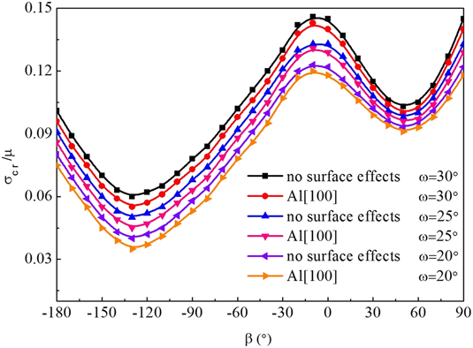
Figure 9 shows the curves of the critical stress with different surface effects and rotational strengths as a function of the angle β. The relevant parameters are φ = π/3, r p = 80 nm, α = −10°, ρc = b, and d2 = 10 nm. As is shown in Fig. 9, when the direction angle of the boundary of rotational nanograin increasing from −180° to 90°, it can produce a pronounced influence on the critical stress. At angles −130° and 52°, critical stress are in the trough. The two angles do not change with the effect of surface effect and rotational strength. In the range of −180° to −10°, −130° should be avoided to improve the critical stress. Similarly, within this range of −10° to 90°, 52° should be avoided. The minimum critical stress can increase with the increase of the rotational strength, which inhibits the nanovoid growth. However, the surface effect will reduce the minimum critical stress, which promotes the growth of the nanovoid.
Normalized critical stress σcr/μ versus the angle β with different surface effects and rotational strengths for φ = π/3, r p = 80 nm, α = −10°, ρc = b, and d2 = 10 nm.

G. Influence of the boundary on the nanovoid growth
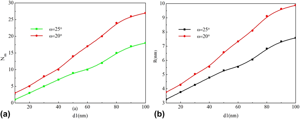
The maximum number N m of emitted dislocations is plotted as a function of the nanograin size for two different values of rotational strength in Fig. 10(a).Fig. 10(b) shows the variation of void size with respect to the nanograin size considering two different rotational strengths. The other parameters are φ = π/3, r p = 80 nm, α = −10°, ρc = b, R = 3 nm, σ0 = 0.14 μ, β = π/6, d2 = 10 nm, λs = 3.4939 N/m, μs = −5.4251 N/m, and τs = 0.5689 N/m in detail calculation. For different rotational strengths, we investigate ten sizes to illustrate the relationship between the maximum dislocation number and the nanograin size. As is shown in Fig. 10(a), the decrease of nanograin size can effectively suppress the nanovoid growth because the maximum number of emitted dislocation decreases. In particular, when the nanograin size is no more than 10 nm, the maximum number of emitted dislocation is quietly low. With the decrease of nanograin size, the distance between the nanograin boundary and the nanovoid surface is very close, so this stress σd generated by the emitted dislocations plays a decisive role, seriously affecting the next dislocation emission. Similar to the study of cracks, the bigger the size of nanograin is, the more the maximum number of emitted dislocation will be. This result is what we do not expect. However, the maximum number of dislocations will obviously decrease when the strength of deformation of nanograin increases, which slows down the growth of the nanovoid. It can be seen from Fig. 10(b) that the void size decreases with the decrease of grain size and the increase of rotation strength. The result clearly states that the nanograin rotation can obviously hinder the growth of nanovoid, which served as a mechanism to improve the ductility of nanocrystalline materials. It is found that the maximum dislocation number decreases with the increase of rotational strength and the decrease of nanograin size, which makes the growth of the nanovoid more difficult.
(a) Maximum number N m versus the nanograin size d1 with different rotational strengths and (b) the variation of the void versus the nanograin size d1 with different rotational strengths for φ = π/3, R = 3 nm, r p = 80 nm, α = −10°, ρc = b, σ0 = 0.14 μ, β = π/6, d2 = 10 nm, λs = 3.4939 N/m, μs = −5.4251 N/m, and τs = 0.5689 N/m.

IV. CONCLUSIONS
In summary, a mechanical model is proposed to investigate the effect of grain rotation on void growth. We focus on the effect of different parameters on the critical stress. Besides, the effect of coupling on void growth is discussed in detail. Major conclusions are summarized as follows:
(1) The higher the rotational strength is, the higher the critical stress will be. The critical stress decreases with the increase of the radius of hole and the nucleation radius of dislocation and the relative distance. However, the critical stress will increase when the rotation coefficient and deformation grain size are increased.
(2) Compared with the influence without surface effects, [111]([110]) surface effects increase (decrease) the critical stress. The critical stress first decreases and then increases with the emission angle of dislocation increases. At angles β = −130° and β = 52°, critical stress are in the trough.
(3) When the grain size d1 is reduced and the rotational strength is increased, the number of the maximum dislocation will be significantly reduced. This will effectively inhibit the growth of the nanovoid.
Therefore, the proposed model can be served as an important tool to improve the toughness of nanocrystalline materials.
ACKNOWLEDGMENTS
This work was supported by the National Natural Science Foundation of China (10502025, 10872087, and 11272143), the Key Project of Chinese Ministry of Education (211061), the Program for Chinese New Century Talents in University (NCET-12-0712), the Ph.D. programs Foundation of Ministry of Education of China (20133221110008), and the Key University Science Research Project of Jiangsu Province (17KJA1300002).