
Introduction
Contemporary techniques of material fabrication allow one to produce stoichiometrically perfect ultrathin metallic films of controlled thickness down to a few monolayers.[Reference Huang, Callegari, Geisler, Brüning, Kern, Prangsma, Wu, Feichtner, Ziegler, Weinmann, Kamp, Forchel, Biagioni, Sennhauser and Hecht1–Reference Shah, Catellani, Reddy, Kinsey, Shalaev, Boltasseva and Calzolari4] Such films are the major components used to create ultrathin metasurfaces for advanced applications in modern optoelectronics and quantum optics including the ultrafast information processing, microscopy, imaging, sensing, and probing the light–matter interactions at the nanoscale.[Reference Stauber, Santos and Brey5–Reference David, Mortensen and Christensen15] As opposed to bulk metals whose electron plasma spectrum and associated optical response are controlled by the material band structure, the plasma properties and optical response of metallic films can also be controlled by adjusting their thickness, chemical composition, and by using properly chosen substrate and superstrate materials.[Reference Bondarev and Shalaev16] This unique tunability makes ultrathin metallic (or plasmonic) films an attractive platform for the design of advanced multifunctional metasurfaces with increased operational bandwidths and reduced losses, metasurfaces that are capable of utilizing the true quantum nature of light to achieve new improved functionalities.[Reference Bondarev and Shalaev17] With the decrease of the thickness, however, the vertical electron confinement becomes stronger, which can lead to new finite-size and dimensionality-related effects.[Reference Manjavacas and García de Abajo11, Reference Bondarev and Shalaev16] These effects require a deeper theoretical insight to understand how important they are and how they can be used to control the optical properties of ultrathin plasmonic films.
Two of us have recently shown theoretically the plasma frequency of ultrathin metallic films to acquire the spatial dispersion typical of two-dimensional (2D) materials such as graphene, gradually shifting to the red as the film thickness decreases, while being constant for relatively thick films.[Reference Bondarev and Shalaev16] This leads to the spatial dispersion and the non-locality connected therewith of the dielectric response function of the film. The dielectric response non-locality we report about is solely a confinement effect, which naturally explains the results of the recent plasma frequency measurements on TiN films of controlled variable thickness.[Reference Shah, Reddy, Kinsey, Shalaev and Boltasseva3] This effect is different from and stronger than the effects commonly known to result from using the hydrodynamical Drude models[Reference David and Christensen6, Reference David and García de Abajo13, Reference David, Mortensen and Christensen15] due to the pressure term in degenerate electron gas systems.[Reference Pines and Bohm18, Reference Ritchie19] Here, we extend our theory to include the analysis of the magneto-dielectric response due to the plasma frequency spatial dispersion of ultrathin metallic films. We show that the properly tuned ultrathin films of finite lateral size and thickness can possess new interesting features such as the resonance magnetic response and the low-frequency negative refraction, which could open up new avenues for potential applications in modern optoelectronics.
Theory
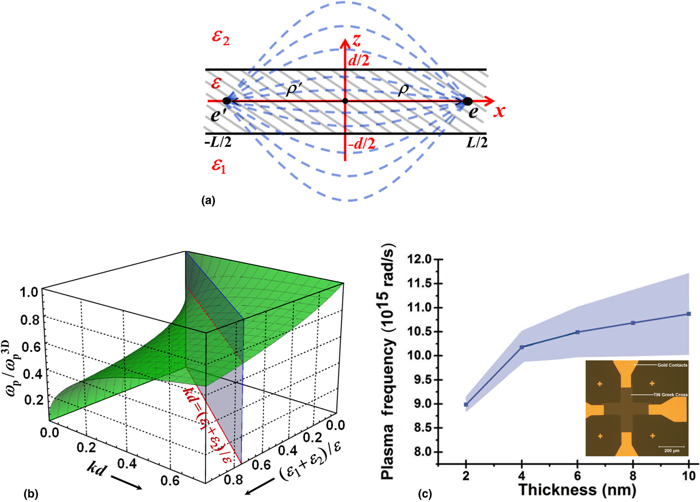
In thin and ultrathin films [see Fig. 1(a)], the Coulomb interaction between charges increases with decreasing thickness if the film background dielectric constant ε is much larger than the dielectric constants ε 1,2 of the substrate and superstrate materials.[Reference Keldysh20, Reference Rytova21] The field produced by the charges in the film outside of their confinement region starts playing a perceptible role with the film thickness reduction. When ε 1,2 ≪ ε and the in-plane distance ρ between the charges is greater than the film thickness d as it is shown in Fig. 1(a), the increased “outside” Coulomb contribution makes the interaction between the charges inside the film much stronger than that in homogeneous medium with the dielectric constant ε. In view of this, the Fourier transform of the inter-electron Coulomb potential in the finite-thickness metallic films (also known as Keldysh potential[Reference Keldysh20]) goes as 4πe 2/k [kd + (ε 1 + ε 2)/ε] with k being the absolute value of the 2D (in-plane) electron quasi-momentum, and not as 4πe 2/k 2 commonly used where k is the 3D quasi-momentum absolute value in bulk materials. In other words, due to the effective dimensionality reduction, the vertical confinement changes the way in which the electrons in the film interact with each other. The plasma frequency calculated using this fact takes the following form[Reference Bondarev and Shalaev16]
 $$\omega _{\rm p} = \omega _{\rm p}(k) = \displaystyle{{\omega _{\rm p}^{{\rm 3D}}} \over {\sqrt {1 + (\varepsilon _1 + \varepsilon _2){\kern 1pt} /\varepsilon kd}}}. $$
(a) Schematic representation of the thin film geometry and sketch of the field line pattern for two confined charges e and e′ separated by the in-plane distance |ρ − ρ′| much greater than the film thickness d. (b) The ratio ω p/ω p3D as given by Eq. (1); the regimes of the relatively thick and ultrathin films are separated by the vertical plane. (c) Plasma frequency extracted from the ellipsometry measurements on ultrathin TiN films (inset) of varied thickness (see Ref. Reference Shah, Reddy, Kinsey, Shalaev and Boltasseva3 for more details), to compare with (b).

Here,  $\omega _{\rm p}^{{\rm 3D}} = \sqrt {4\pi e^2N_{{\rm 3D}}/\varepsilon m^ *} $ is the 3D electron gas plasma frequency with the effective electron mass m* and the volumetric electron density N 3D. One can see that Eq. (1) gives ω p = ω p3D for the relatively thick films with (ε 1 + ε 2)/εkd ≪ 1, whereas
 $\omega _{\rm p}{\kern 1pt} = \omega _{\rm p}^{{\rm 2D}} (k) = {\kern 1pt} \sqrt {4\pi e^2N_{{\rm 2D}}k{\kern 1pt} /{\kern 1pt} (\varepsilon _1{\kern 1pt} + \varepsilon _2)m^ *} $ in the opposite limit of the ultrathin films with (ε 1 + ε 2)/εkd ≫ 1 (N 2D = N 3D d is the surface electron density). The latter expression agrees with the well-known k 1/2 spatial dispersion of the plasma frequency of the 2D electron gas in air,[Reference Davies22] but does show the dependence on the surroundings of the film in the way it occurs for planar monolayer systems such as graphene.[Reference Basov, Fogler, Lanzara, Wang and Zhang23]
Figure 1(b) shows the ratio ω p/ω p3D of Eq. (1) as a function of kd and (ε 1 + ε 2)/ε with the thick and thin film regimes separated by the vertical plane. The plasma frequency ω p is seen to be constant for thick films, whereas for thin films, the spatial dispersion shows up, typical of 2D materials such as graphene,[Reference Basov, Fogler, Lanzara, Wang and Zhang23] gradually shifting ω p to the red as the film thickness decreases. This explains the results of the recent plasma frequency measurements [shown in Fig. 1(c); see Ref. Reference Shah, Reddy, Kinsey, Shalaev and Boltasseva3] done on ultrathin TiN films of controlled varied thickness, and also agrees well with the results of the first-principles density functional simulations reported recently.[Reference Shah, Catellani, Reddy, Kinsey, Shalaev, Boltasseva and Calzolari4]
Spatial dispersion and non-locality
The spatially dispersive plasma frequency (1) is contained in the complex-valued dynamical dielectric response function of the electron gas confined in metallic films. This makes the film dielectric permittivity spatially dispersive, i.e., k-dependent and so non-local. When the spatial dispersion is present, the permittivity is a tensor, not a scalar—even for isotropic layered media shown in Fig. 1(a)—a distinctive direction is generated by the in-plane wave vector k.[Reference Landau and Lifshitz24] When the medium is not only isotropic but also has a center of symmetry, such a non-local dielectric response tensor can be written in terms of the k components as follows
 $$\eqalign{& \varepsilon _{\lambda \mu} (\omega, {\bf k}) = \varepsilon _{\rm t}(\omega, k)\left( {\delta_{\lambda \mu} - \displaystyle{{k_\lambda k_\mu} \over {k^2}}} \right) + \varepsilon _{\rm l}(\omega, k)\displaystyle{{k_\lambda k_\mu} \over {k^2}}, \cr & \quad \lambda, \mu = x,y,}$$
where the transverse ε t and longitudinal ε l response functions depend on k (=|k|) and ω only.[Reference Landau and Lifshitz24] With losses taken into account phenomenologically they can be approximated as
 $$\eqalign{&\displaystyle{{\varepsilon _{\rm t}(\omega, k)} \over \varepsilon} = 1 - \displaystyle{{\omega _{\rm p}^2 (k)} \over {\omega (\omega + i\gamma )}}, \cr &\displaystyle{{\varepsilon _{\rm l}(\omega, k)} \over \varepsilon} = 1 + \displaystyle{{\omega _{\rm p}^2 (k)} \over {\omega _{\rm p}^2 (k) - \omega (\omega + i\gamma )}}.}$$
Here, the (phenomenologic) parameter γ stands to represent the electron inelastic scattering rate and ω p(k) is given by Eq. (1). These expressions (the former is usually referred to as the Drude response function[Reference Manjavacas and García de Abajo11]) are typically used for the description of the isotropic frequency response of the outer shell (s-band) electrons in metals to the perpendicularly and longitudinally polarized electromagnetic fields, respectively, with ε taking into account the positive background of ions screened by the inner shell electrons. In many cases, however, they need to be supplemented with an extra term to account for the interband electronic transitions. The total response function is then referred to as the Drude–Lorentz function.[Reference Reddy, Guler, Kildishev, Boltasseva and Shalaev2–Reference Shah, Catellani, Reddy, Kinsey, Shalaev, Boltasseva and Calzolari4]
It is interesting to evaluate the degree of non-locality associated with the k dependence of ω p in Eq. (3). This can be done by means of the inverse Fourier transformation from the reciprocal 2D space to the direct coordinate 2D space. For ε t(ω,k), in particular, one has the coordinate-dependent specific permittivity (per unit area) of the form
 $$\eqalign{\displaystyle{{\varepsilon _{\rm t}({\bi \rho}, {\bi \rho} {\rm ^{\prime}},\omega )} \over \varepsilon} =\;& \delta ( \vert {\kern 1pt} {\bi \rho} {\rm -} {\bi \rho} {\rm ^{\prime}}{\kern 1pt} \vert ) \cr-& \displaystyle{{{(\omega _{\rm p}^{{\rm 3D}} /2\pi )}^2} \over {\omega (\omega + i\gamma )}}\int_{k_0}^{k_{\rm c}} {dkk} \int_0^{2\pi} {d\varphi} \displaystyle{{e^{{\rm i}{k} \vert {\bi \rho} - {\bi \rho} {\rm ^{\prime}} \vert \cos\varphi}} \over {1 + (\varepsilon _1{\kern 1pt} + \varepsilon _2)/{\kern 1pt} \varepsilon kd}},}$$
where k 0 (=2π/L) and k c represent the plasmon lowest and largest cut-off wave vectors, respectively. For the thick films with (ε 1 + ε 2)/ε k 0d ≪ 1, this gives the local response of the form
 $$\displaystyle{{\varepsilon _{\rm t}({\bi \rho}, {\bi \rho} {\rm ^{\prime}}{,}\omega )} \over \varepsilon} = \left[ {1 - \displaystyle{{{(\omega_{\rm p}^{{\rm 3D}} )}^2} \over {\omega (\omega + i\gamma )}}} \right]\delta ( \vert {\kern 1pt} {\bi \rho - \rho} {\rm ^{\prime}} \vert )$$
For the ultrathin films with (ε 1 + ε 2)/εk cd ≫ 1, one obtains (in the limit L → ∞)
 $$\eqalign{ \displaystyle{{\varepsilon _{\rm t}({\bi \rho}, {\bi {\rho} ^{\prime}}{,}\omega )} \over \varepsilon}& \approx \left[ {1 - \displaystyle{{\varepsilon k_{\rm c}d{(\omega_{\rm p}^{{\rm 3D}} )}^2} \over {(\varepsilon_1 + {\kern 1pt} \varepsilon_2)\omega (\omega + i\gamma )}}} \right] \delta ( \vert {\kern 1pt} {\bi \rho - {\rho} ^{\prime}} \vert ) \cr &\quad + \displaystyle{{\varepsilon k_{\rm c}d{(\omega _{\rm p}^{{\rm 3D}} )}^2} \over {(\varepsilon _1 + \varepsilon _2)\omega (\omega + i\gamma )}} \cdot \displaystyle{{\cos (k_{\rm c} \vert {\bi \rho - {\rho} ^{\prime}} \vert + 3\pi {\kern 1pt} /4)} \over {\sqrt {2\pi ^3k_{\rm c}} \vert {\kern 1pt} {\bi \rho - {\rho} ^{\prime}} \vert ^{5/2}}}}$$
under the extra condition k c|ρ − ρ′| > 1 to specify the distances where the Coulomb interaction of the individual electrons is screened and so their motion in the form of the collective plasma oscillations is well defined. One can now see that the ultrathin film permittivity decays with distance as |ρ − ρ′|−5/2 to represent the confinement-related dielectric response non-locality that we deal herewith.
Dielectric permittivity and magnetic permeability
At frequencies well below the interband transition frequencies, the description of the linear electromagnetic response of an isotropic (centrosymmetric) medium by means of the spatially dispersive dielectric tensor of Eqs. (2) and (3), which includes responses to both perpendicularly and longitudinally polarized electromagnetic waves, is known to be equivalent to the description in terms of the non-dispersive isotropic dielectric permittivity and magnetic permeability, ε(ω) and μ(ω) (see Ref. Reference Landau and Lifshitz24). The equivalency of the two description methods requires
 $$\varepsilon (\omega ) = \mathop {\lim} \limits_{k \to \,k_0} \varepsilon _{\rm t}(\omega, k) = \mathop {\lim} \limits_{k \to \,k_0} \varepsilon _{\rm l}(\omega, k)$$
and
 $$\hbox{1} - \displaystyle{1 \over {\mu (\omega )}} = \displaystyle{{\omega ^2} \over {c^2}}\mathop {\lim} \limits_{k \to \,k_0} \displaystyle{{\varepsilon _{\rm t}(\omega, k) - \varepsilon _{\rm l}(\omega, k)} \over {k^2}}.$$
From Eq. (3), one can easily see that Eq. (5) is fulfilled for frequencies  $\omega \gt \omega _{\rm p}^{{\rm 3D}} \sqrt {2\pi \varepsilon d/(\varepsilon _1{\kern 1pt} + {\kern 1pt} \varepsilon _2)L} $, with the lower boundary controlled by the ratio of the thin film thickness d and lateral size L as shown in Fig. 1(a), to result in
 $$\varepsilon (\omega ) = \varepsilon \left\{ {1 - \displaystyle{{{(\omega_{\rm p}^{{\rm 3D}} )}^2} \over {\lsqb {1 + (\varepsilon_1 + \varepsilon_2)L{\kern 1pt} /2\pi {\kern 1pt} \varepsilon d} \rsqb \omega (\omega + i\gamma )}}} \right\}.$$
In the same frequency range, substituting Eq. (3) into Eq. (6), one obtains
 $$\mu (\omega ) = \left\{ {1 - \displaystyle{{{(\omega_{\rm p}^{{\rm 3D}} )}^2{(L/\lambda_{\rm p}^{{\rm 3D}} )}^2} \over {{\lsqb {1 + (\varepsilon_1 + \varepsilon_2)L{\kern 1pt} /2\pi \varepsilon d} \rsqb }^2{(\omega - i\gamma )}^2}}} \right\}^{ - 1}.$$
For lower frequencies, Eq. (5) is not fulfilled, however, Eqs. (7) and (8) still remain adequate for describing the linear response to the perpendicularly polarized electromagnetic waves alone.[Reference Agranovich and Gartstein25] In Eq. (8), the sign of the imaginary part has been manually reversed to reflect the fact that the constitutive relations are differently defined for the electric and magnetic field vectors E (=D/ε) and B (=μ H), which represent the fundamental vector fields (as opposed to the vectors D and H introduced as a matter of convenience[Reference Jackson26]) and therefore must have the same time evolution.
Equations (7) and (8) represent the “ε(ω) and μ(ω)” method of the isotropic media description as applied to the ultrathin plasmonic films of finite lateral size. This is the equivalent alternative (under the restrictions abovementioned) to the description based on the spatially dispersive dielectric permittivity tensor defined in Eqs. (2) and (3) where the non-local dielectric tensor describes both electric and magnetic field responses.[Reference Landau and Lifshitz24, Reference Agranovich and Gartstein25] For typical experimental values of L ~ 30 µm, ε ~ 10, ε 1 ~ ε 2 ~ 1, the aspect ratio factor in Eqs. (7) and (8) is estimated to be in the range (ε 1 + ε 2)L/2π εd ~ 103–102 for d ~ 1–10 nm.
Discussion
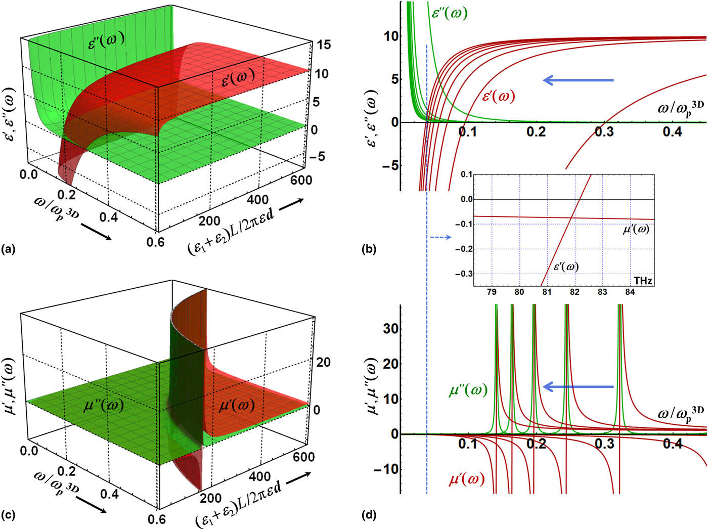
Figure 2 presents our model calculations for the real and imaginary parts of ε(ω) (= ε′ + iε″) and μ(ω) (= μ′ + iμ″) in Eqs. (7) and (8) as functions of the dimensionless frequency ω/ω p3D and the aspect ratio parameter (ε 1 + ε 2)L/2π εd, with the other parameter values as follows: ε = 10, γ/ω p3D = 0.001, and L/λ p3D = 100 (chosen to be close to those of gold[Reference Manjavacas and García de Abajo11]). Figures 2(b) and 2(d) show the contour plots obtained by cutting the graphs in Figs. 2(a) and 2(c) by the parallel vertical planes of constant aspect ratio (ε 1 + ε 2)L/2π εd, with the thick horizontal blue arrows indicating the aspect ratio increase direction. As the aspect ratio parameter increases, for the dielectric permittivity in Figs. 2(a) and 2(b), one can see the red shift of the plasma frequency (zeros of the real parts) accompanied by the dissipative loss reduction (imaginary parts going lower), quite similar to what was earlier reported both experimentally and theoretically.[Reference Shah, Reddy, Kinsey, Shalaev and Boltasseva3, Reference Shah, Catellani, Reddy, Kinsey, Shalaev, Boltasseva and Calzolari4, Reference Bondarev and Shalaev16] The magnetic permeability in Figs. 2(c) and 2(d) exhibits a sharp resonance structure shifting to the red as the aspect ratio parameter increases, with the real parts changing sign and the imaginary parts being sharply peaked at zeros of the real parts. These effects are controlled by the aspect ratio parameter (ε 1 + ε 2)L/2π εd and, as this parameter includes substrate and superstrate material characteristics, allow the tune-up of the magneto-optical properties of ultrathin plasmonic films not only by varying their chemical composition (ε, ω p3D) and material quality (γ) but also by adjusting their L/d ratio (must always be ≫1 though) and by choosing the deposition substrates (ε 1) and coating layers (ε 2) appropriately (with the inequality ε ≫ ε 1,2 still to hold).
(a) Real (red) and imaginary (green) parts of the isotropic dielectric permittivity in Eq. (7) as functions of the dimensionless frequency ω/ω p3D and the aspect ratio parameter (ε 1 + ε 2)L/2π εd of the film. (b) The contour plot one obtains by cutting the graph in (a) with the parallel vertical planes of constant (ε 1 + ε 2)L/2π εd. The thick horizontal blue arrow shows the direction of the (ε 1 + ε 2)L/2π εd increase. (c, d) Same as in (a, b) for the real and imaginary parts of the isotropic magnetic permeability of Eq. (8). The vertical dashed line going through (b, d) indicates the region where the real part of the dielectric permittivity and the real part of the magnetic permeability are both negative, and the inset shows their actual behavior in this region with frequency expressed in THz. See text for more details.

Possibility for low-frequency negative refraction
When described in terms of the “ε(ω) and μ(ω)” approach, an isotropic linear passive medium is known to possess a negative refractive index provided that the real parts of its dielectric permittivity and magnetic permeability are both negative.[Reference Shalaev27, Reference Depine and Lakhtakia28] The vertical dashed line in Figs. 2(b) and 2(d) indicates the domain where this could be possible for the ultrathin plasmonic films of finite lateral size. The inset shows the actual behavior of ε′(ω) and μ′(ω) in this region with the frequency expressed in THz [rescaled from Figs. 2(b) and 2(d) with the bulk plasma frequency ω p3D(Au) ≈ 9 eV = 2179.19 THz[Reference Manjavacas and García de Abajo11]]. One can see that both ε′ and μ′ are negative simultaneously in the IR frequency range. A close inspection of Eqs. (7) and (8) reveals that in order for this to occur, the frequency must satisfy the following inequality
 $$\gamma \;{\rm \ll} \omega \lt \omega _{\rm p}^{{\rm 3D}} \sqrt {\displaystyle{{2\pi \varepsilon d} \over {(\varepsilon _1 + \varepsilon _2)L}}} \hskip 6pt .$$
This condition is exactly opposite to that where the “ε(ω) and μ(ω)” isotropic medium description method of Eqs. (7) and (8) is equivalent to the medium description by means of the spatially dispersive dielectric tensor of Eqs. (2) and (3), making it possible to describe the linear responses to both perpendicularly and longitudinally polarized electromagnetic waves in terms of ε(ω) and μ(ω). However, as discussed above, the “ε(ω) and μ(ω)” method still remains adequate at frequencies in Eq. (9) for describing the linear response to the perpendicularly polarized electromagnetic waves alone, i.e., for the optical spectroscopy experiment description.
From Eq. (9), one can see that the negative refraction domain of the perpendicularly polarized electromagnetic waves is controlled by ω p3D and the inverse aspect ratio parameter of the film on the upper boundary and by the electron inelastic scattering rate on the lower boundary. This domain can be both shrunk and expanded under appropriate material and geometry adjustment. For example, increasing the lateral size of the thin film and/or using a plasmonic material with small ε and ω p3D and relatively large γ can shrink the negative refraction domain down to zero. On the other hand, using very clean (small γ) ultrathin films of finite aspect ratio L/d, made of a plasmonic material with large ε and ω p3D, placed in low-permittivity surroundings (e.g., air), can expand significantly the negative refraction range for perpendicularly polarized electromagnetic waves. Remarkably, such a possibility only exists for the ultrathin plasmonic films of finite lateral size where the electron confinement and associated plasma frequency spatial dispersion result in the dielectric response non-locality to cause magneto-optical effects such as the negative refraction discussed here and the resonance magnetic response discussed above.
Conclusions
In this communication, we discuss some peculiarities of the magneto-dielectric response of ultrathin plasmonic films of finite lateral size. We show that the spatial dispersion and the associated non-locality of the dielectric response, which originate from the confinement-induced plasma frequency spatial dispersion, can result in the new features of the dynamical magnetic response of the film. The magnetic permeability exhibits the sharp resonance structure shifting to the red as the film aspect ratio increases. When tuned appropriately, the ultrathin films of finite lateral size can be negatively refractive in the IR frequency range. These features are consistent with the general causality principle of spatially dispersive media.[Reference Forcella, Prada and Carminati29] They can be controlled by adjusting the film chemical composition (ε, ω p3D), material quality (γ), and the L/d ratio as well as by choosing the deposition substrates (ε 1) and coating layers (ε 2) appropriately. Remarkably,[Reference Bondarev and Shalaev16] these are all solely confinement-related effects different from those commonly known to occur in the hydrodynamical Drude models due to the pressure term in the degenerate electron gas with no confinement included.[Reference David and Christensen6, Reference David and García de Abajo13, Reference David, Mortensen and Christensen15] We believe that our findings open up entirely new avenues for potential applications of ultrathin plasmonic films in modern optoelectronics.
Acknowledgments
I.V.B. is supported by NSF-ECCS-1306871. Work of H.M. is funded by DOE-DE-SC0007117. Work on this project by V.M.S. is supported in part by ONR-N00014-16-1-3003. Discussions with Mikhail Lapine (UT-Sydney, Australia), Alexander Kildishev, Zhaxylyk Kudyshev, and Michael Povolotskyi (all from Purdue University, USA) are gratefully acknowledged.