1. Introduction
Magnetohydrodynamics (MHD) serves as a methodological framework for analysing and characterising the various properties of plasma (Kulsrud Reference Kulsrud1983; Makwana & Yan Reference Makwana and Yan2020; Hoelzl et al. Reference Hoelzl, Huijsmans, Pamela, Bécoulet, Nardon, Artola, Nkonga, Atanasiu, Bandaru and Bhole2021). In MHD, the magnetic flux tube represents a region of concentrated magnetic field lines confined within a distinct spatial boundary (Roberts & Webb Reference Roberts and Webb1978; Davidson Reference Davidson2017; Toriumi & Hotta Reference Toriumi and Hotta2019). The examination of these flux tubes is crucial for understanding magnetic field behaviour across various domains, including astrophysics (Zhugzhda Reference Zhugzhda2000; Yuan et al. Reference Yuan, Spitkovsky, Blandford and Wilkins2019), engineering (Stuikys & Sykulski Reference Stuikys and Sykulski2018; Tang et al. Reference Tang, Ding, Zhang, Lei, Zhao and Duan2018) and space exploration (Levchenko et al. Reference Levchenko, Xu, Mazouffre, Lev, Pedrini, Goebel, Garrigues, Taccogna and Bazaka2020; Bowers et al. Reference Bowers, Slavin, DiBraccio, Poh, Hara, Xu and Brain2021). Moreover, magnetic flux tubes are essential for confining charged particles, such as electrons and ions (Egedal et al. Reference Egedal, Le and Daughton2013; Porto et al. Reference Porto, Elias and Ciardi2023), with implications for plasma dynamics in fusion research (You et al. Reference You, Yun and Bellan2005; Effenberg et al. Reference Effenberg, Feng, Schmitz, Frerichs, Bozhenkov, Hölbe, König, Krychowiak, Pedersen and Reiter2017) and solar physics (Fan Reference Fan2008; Inoue et al. Reference Inoue, Kusano, Büchner and Skála2018; Manek & Brummell Reference Manek and Brummell2021).
Magnetic flux tubes often give rise to complex topological structures such as knots or links, as demonstrated by various studies (see Linton et al. Reference Linton, Dahlburg and Antiochos2001; Ricca & Maggioni Reference Ricca and Maggioni2014; Hao & Yang Reference Hao and Yang2021; Zhao & Scalo Reference Zhao and Scalo2021). These structures are widely recognised as as being part of the solar active zone (Lozitsky et al. Reference Lozitsky, Baranovsky, Lozitska and Leiko2000; Chelpanov et al. Reference Chelpanov, Kobanov and Kolobov2015; MacTaggart et al. Reference MacTaggart, Prior, Raphaldini, Romano and Guglielmino2021). Beckers & Schröter (Reference Beckers and Schröter1968) investigated the structures of strong magnetic fields, revealing that sunspot active regions can generate numerous magnetic knots. Further exploration of the interactions between ascending flux tubes and magnetic knots on the solar surface was provided by Parker (Reference Parker1978), offering insights into the dynamic process of mutual attraction among magnetic knots within sunspot regions.
The evolution of magnetic flux tubes involves topological transformations, including the breaking, rearrangement and reconnection of magnetic field lines (Ricca Reference Ricca1997; Yamada et al. Reference Yamada, Kulsrud and Ji2010; Özdemir Reference Özdemir2021). When magnetic field lines become intertwined, they self-organise into new magnetic configurations, driven by magnetic energy within the plasma (Yin et al. Reference Yin, Daughton, Karimabadi, Albright, Bowers and Margulies2008). This process often generates intense small-scale structures and facilitates the conversion of magnetic energy near line intersections (Mininni et al. Reference Mininni, Pouquet and Montgomery2006). For instance, in Earth’s magnetosphere, magnetic reconnection enables interactions between the planet’s magnetic field and the solar wind, leading to phenomena such as geomagnetic storms (Gonzalez et al. Reference Gonzalez, Joselyn, Kamide, Kroehl, Rostoker, Tsurutani and Vasyliunas1994; Angelopoulos et al. Reference Angelopoulos, Artemyev, Phan and Miyashita2020). Additionally, theoretical insights into the topology of magnetic flux tubes have practical implications for tokamak reactor design (Freidberg et al. Reference Freidberg, Mangiarotti and Minervini2015) and the development of magnetic energy facilities (Domínguez-Lozoya et al. Reference Domínguez-Lozoya, Cuevas, Domínguez, Á. valos-Zú niga and Ramos2021).
We utilise the resistive model as an approximation to capture certain effects of localised turbulence (Biskamp Reference Biskamp1994). However, resistivity alone is insufficient to fully describe turbulence effects in astrophysical systems such as the Sun, where external noise, instabilities and nonlinear interactions influence reconnection dynamics (Somov & Kosugi Reference Somov and Kosugi1997; Ren et al. Reference Ren, Yamada, Gerhardt, Ji, Kulsrud and Kuritsyn2005; Zweibel & Yamada Reference Zweibel and Yamada2009). While zero resistivity recovers the ideal MHD equations, these equations fail to hold even for an infinitesimal resistivity. Fast reconnection, observed in both laboratory and solar environments, occurs when topological changes outpace resistive rates due to turbulence disrupting the frozen-flux condition (Lazarian & Vishniac Reference Lazarian and Vishniac1999; Ji et al. Reference Ji, Daughton, Jara-Almonte, Le, Stanier and Yoo2022), as even in the absence of noise, a sharp current sheet becomes unstable and spontaneously generates turbulence, driving rapid reconnection (Singh et al. Reference Singh, Deverapalli and Khazanov2006). Nevertheless, the resistive model offers a practical approximation for certain aspects of magnetic field dynamics, particularly in modelling geometric and topological changes such as tube splitting, where it provides a reasonable description of relevant phenomena (Cassak et al. Reference Cassak, Shay and Drake2005).
We investigate the generation, evolution and energy release associated with the splitting of magnetic flux tubes – a process wherein a single magnetic tube divides into two or more narrower tubes under specific conditions (Spruit & Roberts Reference Spruit and Roberts1983). Although the role of magnetic splitting in magnetic energy relaxation has been acknowledged in numerous astronomical observations, quantitative studies of this phenomenon have only recently emerged (see Dumin & Somov Reference Dumin and Somov2019; Xiong & Yang Reference Xiong and Yang2020a ). Dumin & Somov (Reference Dumin and Somov2020) examined the topological instability behind magnetic splitting using the Gorbachev–Kel’ner–Somov–Shvarts model, revealing that the splitting pattern is driven by the sudden bifurcation-induced emergence of an additional null point. Another analytical approach was developed by Xiong & Yang (Reference Xiong and Yang2019a , Reference Xiong and Yang2020a ) to construct flux tubes, which was subsequently applied to the study of magnetic splitting. In Xiong & Yang (Reference Xiong and Yang2020a ), the division of magnetic flux tubes is attributed to the Lorentz force, with this effect diminishing as the twist increases. However, a comprehensive theory that fully explains the underlying mechanisms of this phenomenon remains elusive.
We also highlight the influence of vortices on the evolution of magnetic fields (Berciu et al. Reference Berciu, Rappoport and Jankó2005). In the initial stages of evolution, untwisted magnetic tubes generally create a mutually repulsive flow field due to Lorentz forces (Spicer Reference Spicer1982), leading to ongoing splitting of the magnetic tubes and the formation of geometrically filamentary structures commonly linked with magnetic helicity (Ricca Reference Ricca2013). This behaviour resembles the geometric cascade observed in the helical vortex model (Lundgren Reference Lundgren1982, Reference Lundgren1993; Xiong & Yang Reference Xiong and Yang2019b ). However, vortices can disrupt the local flow field, thereby hindering the relaxation of tightly constrained tubular structures into more dispersed floral configurations (Goossens et al. Reference Goossens, Ruderman and Hollweg1995; Xiong & Yang Reference Xiong and Yang2020b ).
This study employs direct numerical simulation (DNS) to investigate the dynamics of magnetic tube evolution and the impact of vortices on MHD flows through their interaction with magnetic fields. In the absence of vortex effects, magnetic tubes typically undergo a topological splitting process as described by Dumin & Somov (Reference Dumin and Somov2020). We study the Lorentz forces within a Frenet–Serret (FS) frame field along magnetic field lines, aiming to identify the primary factors influencing magnetic tube splitting. Owing to the quasi-Lagrangian nature of magnetic and vortex tubes during their evolution, the motion of vortex tubes initially aligns with that of magnetic tubes, resulting in a stable interaction over time. Furthermore, the evolution of helicity demonstrates that magnetic helicity and cross-helicity are conserved in the absence of viscosity, indicating an approximate topological locking between magnetic and vortex lines.
When vortex tubes with relatively high vorticity strength intersect magnetic tubes at a small angle, the proximity enables the vorticity to affect the splitting process by destabilising the vortex dipoles induced by the Lorentz forces. This effect is also evident in the evolution of magnetic energy, which can be divided into stretching and dissipation components. The presence of vortex tubes typically promotes the elongation and redistribution of magnetic field structures, inhibiting magnetic reconnection and consequently reducing the release of magnetic energy. In contrast, the absence of vortex tubes leads to increased magnetic energy release through the stretching term, promoting magnetic tube splitting. Additionally, we investigate the impact of the angle between vortex tubes and magnetic tubes on dynamic evolution. Our findings show that smaller angles hinder the release of magnetic and kinetic energy, while larger angles facilitate magnetic energy release, aiding in the relaxation of the magnetic field.
We observe that the evolution of magnetic tubes, driven by Lorentz forces, leads to the formation of vortex tubes that nearly coincide with the magnetic structures, thereby naturally motivating our configuration for studying magnetic–vortex interactions in physical systems. The set-up, inspired by recent observations of vortex motions in the solar atmosphere by Tziotziou et al. (Reference Tziotziou2023), initialises the system with closely co-located magnetic and vortex tubes. Although idealised, this configuration captures essential features of real-world magnetic–vortex interactions, establishing a foundation for future investigations into the mutual influence of magnetic and vortex tubes under varying conditions and advancing the understanding of more complex MHD flows.
The paper is organised as follows. Section 2 presents the governing equations for MHD flows and describes the numerical simulation using pseudo-spectral methods, including the configuration of our case studies. Section 3 analyses the morphology and dynamics of magnetic and vortical structures in the flow, aiming to elucidate the mechanisms of magnetic tube splitting through the FS frame field and the role of quasi-Lagrangian dynamics in maintaining stability. In § 4, we discuss the influence of vortex dynamics on the evolution of MHD flows, emphasising the sensitivity of tubular structures to dynamic variations. Section 5 concludes with a summary of the findings and recommendations for future research.
2. Direct numerical simulation of MHD
2.1. Numerical methods
We solve the MHD equations (see Priest & Forbes Reference Priest and Forbes2000) as follows:
 \begin{align} \begin{cases} \dfrac {\partial \boldsymbol {u}}{\partial t} + \boldsymbol {u} \boldsymbol{\cdot} \boldsymbol {\nabla } \boldsymbol {u} = - \dfrac {1}{\rho } \boldsymbol {\nabla } p + \dfrac {1}{\rho } {\boldsymbol {F}}_L + \nu _k \nabla ^2 \boldsymbol {u}, \quad \boldsymbol {\nabla } \boldsymbol{\cdot} \boldsymbol {u} = 0, \\[10pt] \dfrac {\partial \boldsymbol {b}}{\partial t} = \boldsymbol {\nabla } \times (\boldsymbol {u} \times \boldsymbol {b}) + \nu _m \nabla ^2 \boldsymbol {b}, \quad \boldsymbol {\nabla } \boldsymbol{\cdot} \boldsymbol {b} = 0. \end{cases} \end{align}
In this system,
 $\boldsymbol {u}$
,
 $\boldsymbol {b}$
,
 $p$
,
 $\rho$
,
 $t$
,
 $\nu _k$
and
 $\nu _m$
represent the velocity, magnetic induction, pressure, mass density, time, kinematic viscosity and magnetic diffusivity, respectively. The magnetic induction
 $ \boldsymbol {b}$
is referred to as the magnetic field in this study, although strictly speaking, the magnetic field in vacuum is given by
 $ \boldsymbol {H} = \boldsymbol {b}/\mu _0$
, where
 $ \mu _0$
denotes the magnetic permeability of free space with a value of
 $ 4\unicode{x03C0} \times 10^{-7} \,\text {H}\,\text{m}^{-1}$
. The Lorentz force,
 ${\boldsymbol {F}}_L$
, is given by
 \begin{equation} {\boldsymbol {F}}_L \equiv \boldsymbol {j} \times \boldsymbol {b}, \end{equation}
where
 $\boldsymbol {j}$
is the current density, related to the magnetic induction
 $\boldsymbol {b}$
through Ampère’s law:
 $\boldsymbol {j} = \boldsymbol {\nabla } \times \boldsymbol {b}/\mu _0$
. The fluid is assumed to be incompressible, with a constant density
 $\rho$
. We set
 $\nu _k = \nu _m$
, which results in a magnetic Prandtl number,
 $Pr_m$
, of unity, defined as the ratio of kinematic viscosity to magnetic diffusivity (Hasimoto Reference Hasimoto1959). This choice simplifies the MHD system, facilitating both mathematical analysis and numerical simulations, particularly in qualitative studies (Linton et al. Reference Linton, Dahlburg and Antiochos2001; Kivotides Reference Kivotides2018).
We adopt the dimensionless form of (2.1), maintaining the original form of the variables for simplicity. We perform numerical simulations of MHD flows within a periodic cube
 $ \Omega$
of side length
 $L=2\unicode{x03C0}$
. The governing equation (2.1) is symmetrically reformulated using the variables
 $\boldsymbol {z}^{\pm } = \boldsymbol {u} \pm \boldsymbol {b}$
, as introduced by Elsasser (Reference Elsasser1950). These equations are solved with a pseudo-spectral method, following the approach of Aluie (Reference Aluie2009), which provides highly accurate computation of spatial derivatives through Fourier transformations. To reduce aliasing errors, we use the two-thirds truncation method, with a maximum wavenumber
 $k_{\textit{max}} \approx N/3$
. Time integration of the Fourier coefficients is carried out using a second-order Runge–Kutta scheme, with the time step chosen to maintain the Courant–Friedrichs–Lewy number below 0.5 for numerical stability. The accuracy of our MHD solver has been validated in previous studies, as cited in Hao et al. (Reference Hao, Xiong and Yang2019), Xiong & Yang (Reference Xiong and Yang2020a
) and Hao & Yang (Reference Hao and Yang2021). Details of grid convergence testing are provided in Appendix A.
Schematic diagram showing the relationship between the intrinsic coordinates
 $(s, \varrho , \vartheta )$
and the Cartesian coordinates
 $(x, y, z)$
. The flux tube is outlined in light blue, with its central axis indicated in yellow-green. The cross-sectional view of the flux tube is enclosed by an orange dashed line.

We investigate the interaction between magnetic and vortical flux tubes using the methodology of Xiong & Yang (Reference Xiong and Yang2019a
, Reference Xiong and Yang2020a
). The initial conditions include tubular structures derived from a continuous, differentiable curve
 $C: \boldsymbol {x} = \boldsymbol {c}(s)$
in three-dimensional space
 $\mathbb {R}^3$
, parametrised by arc length
 $s \in [0, L_C)$
, where
 $L_C$
is the length of the curve. In figure 1, the spatial coordinates
 $\boldsymbol {x} = (x, y, z)$
are expressed in the FS frame as
 $\boldsymbol {x} = \boldsymbol {c}(s) + \varrho \cos \vartheta \, \boldsymbol {N} + \varrho \sin \vartheta \, \boldsymbol {B}$
, where
 $\boldsymbol {T} \equiv \mathrm {d} \boldsymbol {c}/\mathrm {d} s$
is the unit tangent vector,
 $\boldsymbol {N} \equiv (\mathrm {d} \boldsymbol {T}/\mathrm {d} s) / (|\mathrm {d} \boldsymbol {T}/\mathrm {d} s|)$
is the unit normal vector and
 $\boldsymbol {B} \equiv \boldsymbol {T} \times \boldsymbol {N}$
is the unit binormal vector. Here,
 $\varrho = |\boldsymbol {x} - \boldsymbol {c}|$
denotes the distance between
 $\boldsymbol {c}(s)$
and
 $\boldsymbol {x}$
, and
 $\vartheta \in [0, 2\unicode{x03C0} )$
is the angle in the plane defined by
 $\boldsymbol {N}$
and
 $\boldsymbol {B}$
from the unit normal vector to
 $\boldsymbol {x}$
. This configuration positions curve
 $C$
as the central axis of the flux tube.
In the coordinate system
 $(s, \varrho , \vartheta )$
, the flux tube formulation is given by (Xiong & Yang Reference Xiong and Yang2019
a)
 \begin{equation} \boldsymbol {v}(s, \varrho , \vartheta ) = f(\varrho ) \boldsymbol {T}, \end{equation}
where the kernel function is
 $f(\varrho ) = \exp [-\varrho ^2/(2\sigma ^2)]/(2\unicode{x03C0} \sigma ^2)$
with
 $\sigma = 1/(16\sqrt {2\unicode{x03C0} })\approx 0.025$
. The flux tube’s estimated radius
 $ R_v$
is approximately
 $ 5\sigma$
, encompassing over 99.999 % of the toroidal flux. We restrict
 $\boldsymbol {v}$
within
 $ R_v$
, ensuring no self-intersections as long as
 $ R_v$
is smaller than the minimum curvature radius of the central axis
 $ C$
.
We express the initial magnetic field
 $\boldsymbol {b}$
in (2.1) using (2.3) as
 $\boldsymbol {b} = \varGamma _{m}\boldsymbol {v}$
, where
 $\varGamma _{m}$
denotes the circulation of the initial magnetic tube. Similarly, the vorticity field is given by
 $\boldsymbol {\omega } = \varGamma _k \boldsymbol {v}$
, with
 $\varGamma _{k}$
representing the circulation of the initial vortex tube. To obtain the velocity field
 $\boldsymbol {u}$
in (2.1), we solve
 $\boldsymbol {\omega } = \boldsymbol {\nabla } \times \boldsymbol {u}$
and
 $\boldsymbol {\nabla } \boldsymbol{\cdot} \boldsymbol {u} = 0$
using the Fourier transform:
 $ \boldsymbol {u} = \mathcal {F}^{-1} (i \boldsymbol {k} \times \hat {\boldsymbol {\omega }}/|\boldsymbol {k}|^2 ),$
where
 $\mathcal {F}^{-1}$
denotes the inverse Fourier transform,
 $\boldsymbol {k}$
is the wavenumber vector and
 $\hat {\boldsymbol {\omega }} = \mathcal {F}(\boldsymbol {\omega })$
is the Fourier transform of the vorticity field.
2.2. Initial configurations
We generate the initial flux tubes as a pair of interconnected tubes. The parametric equation
 $\boldsymbol {c}(\zeta ) = [c_x(\zeta ), c_y(\zeta ), c_z(\zeta )]$
defines the axis of the first flux tube:
 \begin{equation} \begin{cases} c_x(\zeta ) = \unicode{x03C0} +[1 + 0.5\cos (2\zeta )]\cos (\zeta ),\\ c_y(\zeta ) = \unicode{x03C0} +[1 + 0.5\cos (2\zeta )]\sin (\zeta ),\\ c_z(\zeta ) = \unicode{x03C0} -1.5-0.5\sin (2\zeta ). \end{cases} \end{equation}
The axis of the second flux tube is obtained by rotating the curve from (2.4) clockwise by
 $\unicode{x03C0} /2$
around the line at
 $(x, y) = (\unicode{x03C0} , \unicode{x03C0} )$
. As a result, the initial configuration comprises two interconnected tubes, leading to scenarios where the magnetic and vortex tubes may exhibit either right- or left-handed linkages. For simplicity, the arc length parameter for curve
 $C$
is not used in the above equation. Detailed formulas for computing the geometric properties of curves using a generalised parameter format are provided in Appendix A of Xiong & Yang (Reference Xiong and Yang2020a
).
Isosurfaces of
 $|\boldsymbol {b}|$
and
 $|\boldsymbol {\omega }|$
for (a)
 $L_{m}L_{k}$
with
 $\theta = 0^{\,\circ}$
and (b)
 $L_{m}L_{k}$
with
 $\theta = 30^{\,\circ}$
.

We investigate various magnetic–vortex configurations, considering the presence or absence of initial vorticity and magnetic fields. Specifically, we examine systems with initial left-handed linkage
 $(L_{m}L_{k})$
and right-handed linkage
 $(R_{m}R_{k})$
for magnetic and vortex tubes, as well as pure initial magnetic flow
 $(L_{m}O_{k}, R_{m}O_{k})$
and purely vortical flow
 $(O_{m}L_{k}, O_{m}R_{k})$
, resulting in four distinct reference categories. A right-handed linkage indicates that the two interconnected closed flux tubes share the same orientation, whereas a left-handed linkage implies that they have opposite orientations. While left-handed and right-handed linkages provide a useful classification, the key determinant of their dynamics in MHD flows lies in the relative spatial arrangement and interaction of the tubes, particularly in relation to the alignment of the currents and the reconnection behaviour. We also investigate how the initial angle between the magnetic and vortex tubes influences flux tube evolution. In our notation, ‘
 $R$
’ and ‘
 $L$
’ represent flux tubes with right-handed (positive linking number +2) and left-handed linkages (negative linking number −2), respectively, while ‘
 $O$
’ indicates the absence of corresponding flux tubes. The subscripts ‘
 $m$
’ and ‘
 $k$
’ denote magnetic and kinematic vortex tubes, with ‘
 $\theta$
’ specifying their relative angle.
Figure 2 shows isosurfaces of
 $|\boldsymbol {\omega }|$
and
 $|\boldsymbol {b}|$
for various flux tube configurations, highlighting their coherent and concentrated structures. This confirms the appropriateness of the constructed flux links as initial conditions for DNS. Due to the short time scales considered, the flow structure remains approximately centred within the computational domain. The effect of periodic boundaries on the flow is minimal, given the distance-squared decay of the velocity field as described by the Biot–Savart law.
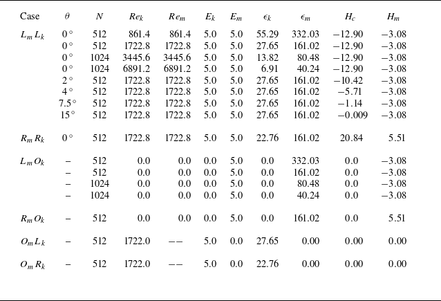
Table 1 provides the parameters and statistics for representative initial flux tubes, including the grid size
 $ N$
, which determines the simulation resolution. It also lists several dimensionless parameters, including the kinetic Reynolds number
 $ Re_{k} = \varGamma _{k} / \nu _k$
, which characterises the relative dominance of inertial forces over viscous dissipation in the kinetic field, and the magnetic Reynolds number
 $ Re_m = Re_k \boldsymbol{\cdot} Pr_m$
, which quantifies the relative importance of inertial versus diffusive effects in the magnetic field. Additionally, the table provides the kinetic energy
 $ E_{k} = \sum _k |\hat {\boldsymbol {u}}(\boldsymbol {k})|^2 / 2$
and magnetic energy
 $ E_{m} = \sum _k |\hat {\boldsymbol {b}}(\boldsymbol {k})|^2 / 2$
, calculated by using Fourier coefficients
 $ \hat {\boldsymbol {b}} = \mathcal {F}(\boldsymbol {b})$
and
 $ \hat {\boldsymbol {u}} = \mathcal {F}(\boldsymbol {u})$
. Additionally, it includes the kinetic dissipation rate
 $ \epsilon _{k} = \nu _k \sum _k (|\boldsymbol {k}| |\hat {\boldsymbol {u}}(\boldsymbol {k})|)^2$
and magnetic dissipation rate
 $ \epsilon _{m} = \nu _m \sum _k (|\boldsymbol {k}| |\hat {\boldsymbol {b}}(\boldsymbol {k})|)^2$
, which quantify the efficiency of the energy dissipation mechanisms in the fluid and magnetic fields. Helicity statistics are also provided, including cross-helicity
 $ H_c = \int _{\varOmega } \boldsymbol {u} \boldsymbol{\cdot} \boldsymbol {b} \, \mathrm {d}\varOmega$
and magnetic helicity
 $ H_{m} = \int _{\varOmega } \boldsymbol {a} \boldsymbol{\cdot} \boldsymbol {b} \, \mathrm {d}\varOmega$
, where
 $ \boldsymbol {a} = \mathcal {F}^{-1}(i \boldsymbol {k} \times \hat {\boldsymbol {b}} / |\boldsymbol {k}|^2)$
. Cross-helicity measures the correlation between the velocity and magnetic fields, while magnetic helicity provides insight into the twist and linkage of the magnetic field lines. For cases with vortex tubes, the initial vorticity flux,
 $\varGamma _k$
, is set to 17.228, while for cases with magnetic tubes, the initial magnetic flux,
 $\varGamma _m$
, is set to 1.036. This ensures that in simulations with both a magnetic tube and a vortex tube, the initial magnetic energy of the magnetic tube equals the initial kinetic energy of the vortex tube.
Parameters and statistics for the initial configurations of selected simulations. Here
 $ R$
and
 $ L$
denote right-handed and left-handed flux tubes with linking numbers +2 and −2, respectively. Subscripts
 $ m$
and
 $ k$
refer to magnetic and kinematic vortex tubes, with
 $ \theta$
specifying their angle. The initial fluxes are set to
 $ \varGamma _k = 17.228$
and
 $ \varGamma _m = 1.036$
, ensuring equal initial magnetic and kinetic energy in simulations with both types of tubes.

Splitting of the magnetic tube for case
 $L_{m}O_k$
with
 $Re_m = 414.4$
at
 $t = 0.0175$
. Integral curves of
 $\boldsymbol {b}$
are coloured by the scalar field
 $\boldsymbol {j} \boldsymbol{\cdot} \boldsymbol {b}$
. The right-hand subfigure provides a zoomed view of the dashed box area from the left-hand subfigure.

We investigate the evolution of magnetic tubes and their interactions with vortex tubes. As shown in figure 3, a phenomenon observed is the splitting of magnetic tubes during their evolution. This study systematically explores this process by integrating theoretical analysis of the governing equations with a quantitative assessment of numerical results. Specifically, vortex dynamics analysis is used to clarify the role of vortex tubes in magnetic tube splitting.
Additionally, we observe that, in our numerical simulations involving both magnetic and vortex tubes, the Lorentz force is substantially larger than the inertial force. This relationship can be characterised by the interaction parameter
 $ N_{I} = \varGamma _m^2 / [\rho \mu _0 Re_k \nu _k\nu _m (R_v)^2 ]=(\varGamma _m^2Re_k)/\rho \mu _0 (\varGamma _k R_v)^2$
, which quantifies the balance between Lorentz and inertial forces in the system (Kivotides Reference Kivotides2018, Reference Kivotides2019). In the simulations presented herein,
 $ N_I \gg 1$
, and in this regime, the morphologies of the vorticity and magnetic field structures exhibit notable similarity. This phenomenon is further explored in the following sections and aligns with the observations of Kivotides (Reference Kivotides2018).
3. Magnetohydrodynamic flows in the FS frame field
3.1. The FS frame fields
To facilitate the analysis of dynamic flow fields, we extend the FS frame throughout the flux tube domain. This FS frame is defined where the magnetic field and the curvature of the magnetic lines are both non-zero, although it is important to note that inflexion points may exist in realistic scenarios. Specifically, we define a FS coordinate system at each point along the magnetic field lines, establishing a unit frame field
 $[\boldsymbol {T}(\boldsymbol {x}), \boldsymbol {N}(\boldsymbol {x}), \boldsymbol {B}(\boldsymbol {x})]$
at locations where the magnetic field is non-zero, as depicted in figure 4. At each point
 $\boldsymbol {c}$
along these magnetic lines, the vectors
 $[\boldsymbol {T}(\boldsymbol {c}), \boldsymbol {N}(\boldsymbol {c}), \boldsymbol {B}(\boldsymbol {c})]$
follow the FS formulas:
 \begin{equation} {\boldsymbol {T}} \boldsymbol{\cdot} \boldsymbol \nabla {\boldsymbol {T}} = \kappa {\boldsymbol {N}},\quad {\boldsymbol {T}} \boldsymbol{\cdot} \boldsymbol \nabla {\boldsymbol {N}} = -\kappa {\boldsymbol {T}} + \tau {\boldsymbol {B}},\quad {\boldsymbol {T}} \boldsymbol{\cdot} \boldsymbol \nabla {\boldsymbol {B}} =-\tau {\boldsymbol {N}}. \end{equation}
Here,
 $\kappa$
and
 $\tau$
represent the curvature and torsion of the curve, respectively.
Frenet–Serret frames generated by magnetic field lines. The unit tangent, normal and binormal vectors are represented by black, blue and red arrows, respectively.

Let
 $\boldsymbol {T}$
,
 $\boldsymbol {N}$
and
 $\boldsymbol {B}$
be column vectors that form an orthogonal matrix
 $\mathcal {O} = [\boldsymbol {T}, \boldsymbol {N}, \boldsymbol {B}]$
. Utilising the properties of the matrix trace, for any matrix
 $\boldsymbol {A}$
, we have
 \begin{equation} \textrm {Tr}(\boldsymbol A)= \textrm {Tr}(\mathcal {O}^{-1}\boldsymbol A \mathcal {O})= \textrm {Tr}(\mathcal {O}^{T}\boldsymbol A \mathcal {O})= \boldsymbol T^T\boldsymbol A \boldsymbol T + \boldsymbol N^T\boldsymbol A \boldsymbol N + \boldsymbol B^T\boldsymbol A \boldsymbol B. \end{equation}
Since
 $\boldsymbol {T}$
,
 $\boldsymbol {N}$
and
 $\boldsymbol {B}$
are unit vectors, and applying (3.2) and
 $\boldsymbol {\nabla } \boldsymbol{\cdot} \boldsymbol {A} = \text {Tr}(\boldsymbol {\nabla } \boldsymbol {A})$
, we obtain
 \begin{equation} \begin{cases} \boldsymbol \nabla \boldsymbol{\cdot} \boldsymbol T = \boldsymbol T \boldsymbol{\cdot} \boldsymbol \nabla \boldsymbol T \boldsymbol{\cdot} \boldsymbol T + \boldsymbol N \boldsymbol{\cdot} \boldsymbol \nabla \boldsymbol T \boldsymbol{\cdot} \boldsymbol N + \boldsymbol B \boldsymbol{\cdot} \boldsymbol \nabla \boldsymbol T \boldsymbol{\cdot} \boldsymbol B= \boldsymbol N \boldsymbol{\cdot} \boldsymbol \nabla \boldsymbol T \boldsymbol{\cdot} \boldsymbol N + \boldsymbol B \boldsymbol{\cdot} \boldsymbol \nabla \boldsymbol T \boldsymbol{\cdot} \boldsymbol B , \\ \boldsymbol \nabla \boldsymbol{\cdot} \boldsymbol N = \boldsymbol T \boldsymbol{\cdot} \boldsymbol \nabla \boldsymbol N \boldsymbol{\cdot} \boldsymbol T + \boldsymbol N \boldsymbol{\cdot} \boldsymbol \nabla \boldsymbol N \boldsymbol{\cdot} \boldsymbol N + \boldsymbol B \boldsymbol{\cdot} \boldsymbol \nabla \boldsymbol N \boldsymbol{\cdot} \boldsymbol B =\boldsymbol T \boldsymbol{\cdot} \boldsymbol \nabla \boldsymbol N \boldsymbol{\cdot} \boldsymbol T + \boldsymbol B \boldsymbol{\cdot} \boldsymbol \nabla \boldsymbol N \boldsymbol{\cdot} \boldsymbol B, \\ \boldsymbol \nabla \boldsymbol{\cdot} \boldsymbol B =\boldsymbol T \boldsymbol{\cdot} \boldsymbol \nabla \boldsymbol B \boldsymbol{\cdot} \boldsymbol T + \boldsymbol N \boldsymbol{\cdot} \boldsymbol \nabla \boldsymbol B \boldsymbol{\cdot} \boldsymbol N + \boldsymbol B \boldsymbol{\cdot} \boldsymbol \nabla \boldsymbol B \boldsymbol{\cdot} \boldsymbol B =\boldsymbol T \boldsymbol{\cdot} \boldsymbol \nabla \boldsymbol B \boldsymbol{\cdot} \boldsymbol T +\boldsymbol N \boldsymbol{\cdot} \boldsymbol \nabla \boldsymbol B \boldsymbol{\cdot} \boldsymbol N. \\ \end{cases} \end{equation}
Additionally, for three-dimensional vectors
 $\boldsymbol f$
and
 $\boldsymbol g$
, using
 \begin{equation} \boldsymbol \nabla \times (\boldsymbol f \times \boldsymbol g) = -(\boldsymbol \nabla \boldsymbol{\cdot} \boldsymbol f)\boldsymbol g +(\boldsymbol \nabla \boldsymbol{\cdot} \boldsymbol g)\boldsymbol f +\boldsymbol g \boldsymbol{\cdot} \boldsymbol \nabla \boldsymbol f - \boldsymbol f \boldsymbol{\cdot} \boldsymbol \nabla \boldsymbol g \end{equation}
and (3.3), we obtain
 \begin{equation} \begin{aligned} \boldsymbol \nabla \times \boldsymbol T &= \boldsymbol \nabla \times (\boldsymbol N \times \boldsymbol B) = -(\boldsymbol \nabla \boldsymbol{\cdot} \boldsymbol N)\boldsymbol B +(\boldsymbol \nabla \boldsymbol{\cdot} \boldsymbol B)\boldsymbol N +\boldsymbol B \boldsymbol{\cdot} \boldsymbol \nabla \boldsymbol N - \boldsymbol N \boldsymbol{\cdot} \boldsymbol \nabla \boldsymbol B\\ &= ( \boldsymbol N \boldsymbol{\cdot} \boldsymbol \nabla \boldsymbol T \boldsymbol{\cdot} \boldsymbol B - \boldsymbol B \boldsymbol{\cdot} \boldsymbol \nabla \boldsymbol T \boldsymbol{\cdot} \boldsymbol N) \boldsymbol T +(\boldsymbol \nabla \boldsymbol{\cdot} \boldsymbol B+\boldsymbol N \boldsymbol{\cdot} \boldsymbol \nabla \boldsymbol N \boldsymbol{\cdot} \boldsymbol B)\boldsymbol N\\ & \quad +(\boldsymbol B \boldsymbol{\cdot} \boldsymbol \nabla \boldsymbol N \boldsymbol{\cdot} \boldsymbol B-\boldsymbol \nabla \boldsymbol{\cdot} \boldsymbol N)\boldsymbol B \\ &= ( \boldsymbol N \boldsymbol{\cdot} \boldsymbol \nabla \boldsymbol T \boldsymbol{\cdot} \boldsymbol B - \boldsymbol B \boldsymbol{\cdot} \boldsymbol \nabla \boldsymbol T \boldsymbol{\cdot} \boldsymbol N) \boldsymbol T +(\boldsymbol T \boldsymbol{\cdot} \boldsymbol \nabla \boldsymbol B \boldsymbol{\cdot} \boldsymbol T)\boldsymbol N -(\boldsymbol T \boldsymbol{\cdot} \boldsymbol \nabla \boldsymbol N \boldsymbol{\cdot} \boldsymbol T)\boldsymbol B. \end{aligned} \end{equation}
Similarly, we have
 \begin{equation} \begin{cases} \boldsymbol \nabla \times \boldsymbol N = -(\boldsymbol N \boldsymbol{\cdot} \boldsymbol \nabla \boldsymbol B \boldsymbol{\cdot} \boldsymbol N)\boldsymbol T+ ( \boldsymbol B \boldsymbol{\cdot} \boldsymbol \nabla \boldsymbol N \boldsymbol{\cdot} \boldsymbol T - \boldsymbol T \boldsymbol{\cdot} \boldsymbol \nabla \boldsymbol N \boldsymbol{\cdot} \boldsymbol B) \boldsymbol N +(\boldsymbol N \boldsymbol{\cdot} \boldsymbol \nabla \boldsymbol T \boldsymbol{\cdot} \boldsymbol N)\boldsymbol B ,\\ \boldsymbol \nabla \times \boldsymbol B = (\boldsymbol B \boldsymbol{\cdot} \boldsymbol \nabla \boldsymbol N \boldsymbol{\cdot} \boldsymbol B)\boldsymbol T -(\boldsymbol B \boldsymbol{\cdot} \boldsymbol \nabla \boldsymbol T \boldsymbol{\cdot} \boldsymbol B)\boldsymbol N + ( \boldsymbol T \boldsymbol{\cdot} \boldsymbol \nabla \boldsymbol B \boldsymbol{\cdot} \boldsymbol N - \boldsymbol N \boldsymbol{\cdot} \boldsymbol \nabla \boldsymbol B \boldsymbol{\cdot} \boldsymbol T) \boldsymbol B . \end{cases} \end{equation}
Substituting (3.1) into (3.3), (3.5) and (3.6) yields
 \begin{equation} \begin{cases} \boldsymbol \nabla \boldsymbol{\cdot} \boldsymbol T =\boldsymbol N \boldsymbol{\cdot} \boldsymbol \nabla \boldsymbol T \boldsymbol{\cdot} \boldsymbol N + \boldsymbol B \boldsymbol{\cdot} \boldsymbol \nabla \boldsymbol T \boldsymbol{\cdot} \boldsymbol B , \\ \boldsymbol \nabla \boldsymbol{\cdot} \boldsymbol N =-\kappa + \boldsymbol B \boldsymbol{\cdot} \boldsymbol \nabla \boldsymbol N \boldsymbol{\cdot} \boldsymbol B, \\ \boldsymbol \nabla \boldsymbol{\cdot} \boldsymbol B =\boldsymbol N \boldsymbol{\cdot} \boldsymbol \nabla \boldsymbol B \boldsymbol{\cdot} \boldsymbol N\\ \end{cases} \end{equation}
and
 \begin{equation} \begin{cases} \boldsymbol \nabla \times \boldsymbol T = ( \boldsymbol N \boldsymbol{\cdot} \boldsymbol \nabla \boldsymbol T \boldsymbol{\cdot} \boldsymbol B - \boldsymbol B \boldsymbol{\cdot} \boldsymbol \nabla \boldsymbol T \boldsymbol{\cdot} \boldsymbol N) \boldsymbol T +\kappa \boldsymbol B , \\ \boldsymbol \nabla \times \boldsymbol N =-(\boldsymbol N \boldsymbol{\cdot} \boldsymbol \nabla \boldsymbol B \boldsymbol{\cdot} \boldsymbol N)\boldsymbol T-( \tau + \boldsymbol B \boldsymbol{\cdot} \boldsymbol \nabla \boldsymbol T \boldsymbol{\cdot} \boldsymbol N ) \boldsymbol N +(\boldsymbol N \boldsymbol{\cdot} \boldsymbol \nabla \boldsymbol T \boldsymbol{\cdot} \boldsymbol N)\boldsymbol B, \\ \boldsymbol \nabla \times \boldsymbol B = (\boldsymbol B \boldsymbol{\cdot} \boldsymbol \nabla \boldsymbol N \boldsymbol{\cdot} \boldsymbol B)\boldsymbol T -(\boldsymbol B \boldsymbol{\cdot} \boldsymbol \nabla \boldsymbol T \boldsymbol{\cdot} \boldsymbol B)\boldsymbol N + (\boldsymbol N \boldsymbol{\cdot} \boldsymbol \nabla \boldsymbol T\boldsymbol{\cdot} \boldsymbol B- \tau ) \boldsymbol B. \\ \end{cases} \end{equation}
3.2. Lorentz force in the FS frame field
By aligning the FS frame with the magnetic field lines, the tangent vector
 $\boldsymbol {T}$
is made parallel to the magnetic field. Within this coordinate system, we investigate the Lorentz force acting on the magnetic tube and elucidate the mechanism underlying its splitting.
Using the FS frame field, the Lorentz force, as expressed in (2.2), can be represented as
 \begin{equation} {\boldsymbol {F}}_L =-\boldsymbol{\nabla} {\boldsymbol {b}} \boldsymbol{\cdot} {\boldsymbol {b}} + {\boldsymbol {b}} \boldsymbol{\cdot} \boldsymbol{\nabla} {\boldsymbol {b}} = -\tfrac {1}{2}\boldsymbol{\nabla} b^2 + b({\boldsymbol {T}} \boldsymbol{\cdot} \boldsymbol{\nabla} b){\boldsymbol {T}} +\kappa b^2 {\boldsymbol {N}}. \end{equation}
Here,
 $\kappa$
denotes the curvature of the magnetic lines. We remark that
 $(\boldsymbol {T}, \boldsymbol {B}, \boldsymbol {N})$
and
 $\kappa$
are computed for each magnetic field line considered as a parametrised curve. Consequently, these quantities define fields that are distributed throughout the flux tube. In Ricca (Reference Ricca2005), the Lorentz force is derived through the geometry of magnetic field lines, with a focus on their curvature and torsion. The study emphasises how the curvature of the magnetic field lines contributes to the instability of flux tubes, particularly when inflection points are present. Similarly, (3.9) provides a geometrical interpretation of the forces acting on the flux tubes, highlighting the role of curvature in destabilising the magnetic structures.
Given the divergence-free property of the vector field
 $\boldsymbol {b}$
in (2.1), we arrive at the following relation:
 \begin{equation} b \boldsymbol \nabla \boldsymbol{\cdot} {\boldsymbol {T}} + {\boldsymbol {T}} \boldsymbol{\cdot} \boldsymbol \nabla b=0. \end{equation}
Substituting (3.10) into (3.9) yields
 \begin{equation} {\boldsymbol {F}}_L =-\tfrac {1}{2}\boldsymbol \nabla b^2 + b^2\left [-(\boldsymbol \nabla \boldsymbol{\cdot} {\boldsymbol {T}}) {\boldsymbol {T}}+\kappa {\boldsymbol {N}} \right ]. \end{equation}
We focus on the influence of the Lorentz force on vorticity evolution to elucidate the vortex dynamics induced by MHD effects. To evaluate the vorticity evolution, we apply the curl operator to the first equation in (2.1), yielding
 \begin{equation} \frac {{\mathrm{D}} \omega }{{\mathrm{D}}t}=\omega \boldsymbol{\cdot} \boldsymbol \nabla {\boldsymbol {u}}+\nu _k\nabla ^2 \omega +\boldsymbol \nabla \times {\boldsymbol {F}}_L. \end{equation}
Here,
 $ {\mathrm{D}}/{\mathrm{D}}t= \partial /\partial t + \boldsymbol {u} \boldsymbol{\cdot} \boldsymbol {\nabla }$
represents the material derivative. This Lagrangian equation describes the dynamics of vorticity during the shearing process. The vorticity generation arises from the curl of the Lorentz force, which is induced by the magnetic field.
Taking the curl of (3.11) yields
 \begin{equation} \boldsymbol \nabla \times {\boldsymbol {F}}_L= \boldsymbol \nabla \times \left \{b^2\left [-(\boldsymbol \nabla \boldsymbol{\cdot} {\boldsymbol {T}}) {\boldsymbol {T}}+\kappa {\boldsymbol {N}} \right ]\right \}. \end{equation}
Equation (3.13) reveals that the curl of the Lorentz force splits into two components:
 $\boldsymbol {\nabla } \times {\boldsymbol {F}}_L = \boldsymbol {\omega }^{g} + \boldsymbol {\omega }^{b}$
. The first component,
 $\boldsymbol {\omega }^{g}$
, is defined as
 \begin{equation} \boldsymbol {\omega }^{g} = b^2 \boldsymbol \nabla \times \left [-(\boldsymbol \nabla \boldsymbol{\cdot} {\boldsymbol {T}}) {\boldsymbol {T}}+\kappa {\boldsymbol {N}} \right ] \end{equation}
and is sensitive to the geometric configuration of the magnetic field lines. On the other hand, the second component,
 $\boldsymbol {\omega }^{b}$
, is given by
 \begin{equation} \boldsymbol \omega ^{b}=(\boldsymbol \nabla b^2) \times \left [-(\boldsymbol \nabla \boldsymbol{\cdot} {\boldsymbol {T}}) {\boldsymbol {T}}+\kappa {\boldsymbol {N}} \right ] \end{equation}
and is sensitive to variations in magnetic intensity.
The splitting of the magnetic tube is noticeable in the early stages of its evolution. During this phase, the Lorentz force is largely influenced by the initial magnetic field configuration. Accordingly, we examine the initial condition described by (2.3), where the helicity of the vector field is influenced by the writhe of the tube axis (Xiong & Yang Reference Xiong and Yang2019a ). At this stage, the magnetic field lines have a relatively simple structure, which allows for a more straightforward decomposition of the Lorentz force.
Within the flux tube of radius
 $R_v$
, the flux lines corresponding to (2.3) are parallel, thus satisfying
 \begin{equation} \boldsymbol N \boldsymbol{\cdot} \boldsymbol \nabla \boldsymbol T = \boldsymbol B \boldsymbol{\cdot} \boldsymbol \nabla \boldsymbol T = \boldsymbol 0. \end{equation}
Since
 $\boldsymbol \nabla \boldsymbol T$
is a second-order tensor, its contraction with vectors yields a vector. From (3.1) and (3.16), we also derive the following system of equations:
 \begin{equation} \boldsymbol B \boldsymbol{\cdot} \boldsymbol \nabla \left (\boldsymbol T \boldsymbol{\cdot} \boldsymbol \nabla \boldsymbol T\right ) =\boldsymbol 0,\quad\boldsymbol N \boldsymbol{\cdot} \boldsymbol \nabla \left (\boldsymbol T \boldsymbol{\cdot} \boldsymbol \nabla \boldsymbol T\right ) =\kappa ^2 \boldsymbol N, \end{equation}
which leads to
 \begin{equation} \boldsymbol B \boldsymbol{\cdot} \boldsymbol \nabla \boldsymbol N \boldsymbol{\cdot} \boldsymbol B= \boldsymbol B \boldsymbol{\cdot} \boldsymbol \nabla \left (\frac {\boldsymbol T \boldsymbol{\cdot} \boldsymbol \nabla \boldsymbol T }{\kappa } \right ) \boldsymbol{\cdot} \boldsymbol B=0,\quad \boldsymbol N \boldsymbol{\cdot} \boldsymbol \nabla \boldsymbol B \boldsymbol{\cdot} \boldsymbol N= -\boldsymbol N \boldsymbol{\cdot} \boldsymbol \nabla \left (\frac {\boldsymbol T \boldsymbol{\cdot} \boldsymbol \nabla \boldsymbol T }{\kappa } \right ) \boldsymbol{\cdot} \boldsymbol B=0. \end{equation}
Using (3.16) and (3.18), the expressions represented by (3.7) and (3.8) can be simplified to the following results:
 \begin{equation} \boldsymbol \nabla \boldsymbol{\cdot} \boldsymbol T = 0,\quad \boldsymbol \nabla \boldsymbol{\cdot} \boldsymbol N =-\kappa , \quad \boldsymbol \nabla \boldsymbol{\cdot} \boldsymbol B =0 \end{equation}
and
 \begin{equation} \boldsymbol \nabla \times \boldsymbol T = \kappa \boldsymbol B , \quad \boldsymbol \nabla \times \boldsymbol N =- \tau \boldsymbol N, \quad \boldsymbol \nabla \times \boldsymbol B =- \tau \boldsymbol B. \end{equation}
Here,
 $\kappa$
and
 $\tau$
denote the curvature and torsion of the curve, respectively.
(a) Isosurface of
 $|{\boldsymbol {b}}|$
for the initial flux tube from (2.3), colour-coded by
 $-{\boldsymbol {B}} \boldsymbol{\cdot} \boldsymbol \nabla (b^2 \kappa )$
. Black lines are integrals of
 $-{\boldsymbol {B}} \boldsymbol{\cdot} \boldsymbol \nabla (b^2 \kappa ) {\boldsymbol {T}}$
. (b) Zoomed view of the flux tube near the region marked by the black square in (a), with black lines indicating the integral curves of
 $\boldsymbol {\nabla } \times (\boldsymbol {\nabla } \times {\boldsymbol {F}}_L)$
, illustrating the dipole structure induced by the magnetic field.

(a) Initial geometry of a single connected magnetic tube in the linked configuration
 $L_{m}O_{k}$
. The grey semi-transparent tube shows the isosurface of magnetic field strength, with curvature indicated by the colour-coded centreline. The vectors along the centreline represent the binormal vector
 $\boldsymbol {B}$
, with their length and colour corresponding to the torsion
 $\tau$
. Positions A, B and C correspond to the locations of maximum curvature, minimum curvature and maximum torsion, respectively. (b) Isosurface of
 $|\boldsymbol {b}| = 50$
at
 $t = 0.01$
, with red arrows indicating the direction of the binormal vector. Zoomed views of (b) are provided in (c) near A, (d) near B and (e) near C. The distance between the split tubes is denoted by
 $d$
.

We remark that both
 $\boldsymbol {B}$
and
 $\boldsymbol {N}$
in (3.20) are Beltrami vector fields (see Reed Reference Reed1995), which can be linked to chaotic magnetic lines in MHD flows (see Smiet et al. Reference Smiet, Candelaresi, Thompson, Swearngin, Dalhuisen and Bouwmeester2015). The analysis method used for this local frame field is similar to the approach of Gibbon et al. (Reference Gibbon, Holm, Kerr and Roulstone2006) for quaternions, as both involve differentiating the local frame to capture the fluid’s key dynamics.
Using (3.19) and (3.20), we simplify (3.13) to
 \begin{equation} \boldsymbol \nabla \times {\boldsymbol {F}}_L=\boldsymbol \nabla \times \left(b^2\kappa {\boldsymbol {N}}\right)=- \left[\boldsymbol B \boldsymbol{\cdot} \boldsymbol \nabla \left(b^2 \kappa \right)\right] \boldsymbol T - b^2 \kappa \tau \boldsymbol N + b^2 (\boldsymbol T \boldsymbol{\cdot} \boldsymbol \nabla \kappa ) {\boldsymbol {B}}. \end{equation}
In this study, dynamical interactions are observed within the elongated tubular structures where
 \begin{equation} \left|\left[\boldsymbol B \boldsymbol{\cdot} \boldsymbol \nabla \left(b^2 \kappa \right)\right] \boldsymbol T\right| \gg \left|b^2 \kappa \tau \boldsymbol N\right|\,\,\textrm {and}\,\, \left|\left[\boldsymbol B \boldsymbol{\cdot} \boldsymbol \nabla \left(b^2 \kappa \right)\right] \boldsymbol T\right| \gg \left| b^2 (\boldsymbol T \boldsymbol{\cdot} \boldsymbol \nabla \kappa ) {\boldsymbol {B}}\right|. \end{equation}
This dominance arises due to the typically large gradient of
 $ b$
. Consequently, the first term in (3.21) is the primary contributor to the evolution of the magnetic tube.
Figure 5 shows the distribution of the magnitude of the first term from (3.21) along the initial magnetic tube described by (2.3). The term
 $[- {\boldsymbol {B}} \boldsymbol{\cdot} \boldsymbol {\nabla } (b^2 \kappa )] {\boldsymbol {T}}$
dominates over the other terms, creating a vortex source along the tube’s axis. Additionally, this term varies in sign along the binormal direction, indicating opposing vortex sources, as illustrated in figures 5(a) and 5(b). The other terms,
 $|b^2 \kappa \tau \boldsymbol N|$
and
 $|b^2 ({\boldsymbol {T}} \boldsymbol{\cdot} \boldsymbol \nabla \kappa )\boldsymbol B|$
, reach their maxima where
 $\kappa \tau$
and
 $({\boldsymbol {T}} \boldsymbol{\cdot} \boldsymbol \nabla \kappa )$
are largest, respectively. However, these terms are generally much smaller than the first term (figures not shown).
Figure 6(a) shows the initial distributions of curvature
 $\kappa$
, torsion
 $\tau$
and binormal vector
 $\boldsymbol {B}$
along the central line of one of the flux tubes in the
 $L_{m}O_{k}$
case. The variations in curvature and torsion are relatively small. Positions A, B and C correspond to the locations of maximum curvature, minimum curvature and maximum torsion, respectively. Figure 6(b) indicates that the splitting direction is closely aligned with the binormal direction of the initial magnetic tube. At position A, where curvature is greater than that at B, the distance between the split tubes is larger, as shown in figures 6(c) and 6(d). It is observed that greater curvature intensifies the formation of vortex pairs, thereby accelerating the splitting of the tube. Figure 6(e) illustrates that twisting can hinder the magnetic tube’s splitting, in agreement with Xiong & Yang (Reference Xiong and Yang2020b
).
We remark that each term in (3.21) involves curvature. For instance, in a one-dimensional cylindrical magnetic tube with a flux distribution described by (2.3), where
 $\kappa = 0$
, the curl of the Lorentz force,
 $\boldsymbol \nabla \times {\boldsymbol {F}}_L$
, equals zero. Consequently, such a cylindrical magnetic tube does not act as a source of vorticity and thus does not lead to the splitting of the magnetic tube.
Isosurfaces of
 $|\boldsymbol {b}|$
for a flow with an initially toroidal magnetic tube of constant curvature
 $\kappa = 4$
for (a)
 $|\boldsymbol {b}| = 50$
at
 $t = 0$
and (b)
 $|\boldsymbol {b}| = 20$
at
 $t = 0.005$
. The isosurfaces are colour-coded by
 ${\boldsymbol {T}} \boldsymbol{\cdot} (\boldsymbol \nabla \times {\boldsymbol {F}}_L)$
, with streamlines integrated along
 $\boldsymbol {u}$
in (b).

If the initial magnetic tube possesses curvature, even if it remains constant along the magnetic field lines, tube splitting can still occur. For example, for a magnetic tube with its central line lying in a plane and under the conditions
 $\tau = 0$
and
 $\boldsymbol {T} \boldsymbol{\cdot} \boldsymbol {\nabla } \kappa = 0$
, the expression of (3.21) simplifies to
 $\boldsymbol \nabla \times {\boldsymbol {F}}_L = -(\kappa \boldsymbol {B} \boldsymbol{\cdot} \boldsymbol {\nabla } b^2) \boldsymbol {T}$
. This indicates that the vorticity source is aligned parallel to the magnetic tube.
Figures 7(a) and 7(b) illustrate the evolution of the
 $|{\boldsymbol {b}}|$
isosurface, coloured by
 $\boldsymbol {T} \boldsymbol{\cdot} (\boldsymbol \nabla \times {\boldsymbol {F}}_L)$
, at
 $t = 0$
and
 $0.005$
. The initial toroidal magnetic tube generates opposing vortex sources in the positive and negative
 $z$
directions, causing them to move apart. As they separate, the split tubes continue to produce opposing vortex sources, which may lead to sustained tube splitting. In this magnetic tube configuration, we further confirm that a larger curvature
 $\kappa$
leads to a greater separation between the split tubes, driven by the stronger vortex pairs induced by
 $-(\kappa \boldsymbol {B} \boldsymbol{\cdot} \boldsymbol {\nabla } b^2) \boldsymbol {T}$
.
3.3. Material properties of integral curves in vector fields
A key feature observed during the evolution is that the magnetic and vortex tubes exhibit quasi-Lagrangian characteristics, approximately following the fluid velocity field while interacting with each other. This behaviour leads to the vortex tubes induced by the magnetic field reflecting the motion of the magnetic tubes in the early stages, including similar splitting phenomena. We explore this behaviour through an analysis of the governing equations for the vorticity and magnetic fields.
Specifically, despite the effects of magnetic interactions, the flow field associated with the evolution of strong magnetic tubes closely follows the Helmholtz (Reference Helmholtz1858) vorticity conservation theorem and the Alfvén (Reference Alfvén1943) frozen-in field theorem. The near-preservation of these conservation laws underscores the robustness of Lagrangian dynamics, even under strong magnetic influences.
To analyse the temporal evolution of the vorticity field, we neglect viscosity and apply the approximation
 \begin{equation} \boldsymbol \nabla \times {\boldsymbol {F}}_L\approx -\left[{\boldsymbol {B}}\boldsymbol{\cdot} \boldsymbol \nabla \left(b^2\kappa \right)\right]{\boldsymbol {T}} \end{equation}
to (3.21). Consequently, (3.12) simplifies to
 \begin{equation} \frac {{\mathrm{D}} \omega }{{\mathrm{D}}t}\approx \omega \boldsymbol{\cdot} \boldsymbol \nabla {\boldsymbol {u}}-\left[{\boldsymbol {B}}\boldsymbol{\cdot} \boldsymbol \nabla \left(b^2\kappa \right)\right]{\boldsymbol {T}}. \end{equation}
For the temporal evolution of the magnetic field, we consider the second equation in (2.1). By substituting
 $ \boldsymbol {\nabla } \times (\boldsymbol {u} \times \boldsymbol {b})$
with
 $ (\boldsymbol {b} \boldsymbol{\cdot} \boldsymbol {\nabla } \boldsymbol {u} - \boldsymbol {u} \boldsymbol{\cdot} \boldsymbol {\nabla } \boldsymbol {b})$
and neglecting magnetic viscous dissipation, the equation simplifies to
 \begin{equation} \frac {{\mathrm{D}} \boldsymbol {b}}{{\mathrm{D}}t} \approx \boldsymbol {b} \boldsymbol{\cdot} \boldsymbol {\nabla } \boldsymbol {u}. \end{equation}
Thus, both the magnetic equation (3.25) and the vorticity equation (3.24) can be approximately reduced to a unified form:
 \begin{equation} \frac {{\mathrm{D}}{\boldsymbol {L}}}{{\mathrm{D}}t}={\boldsymbol {L}}\boldsymbol{\cdot} \boldsymbol \nabla {\boldsymbol {u}}+\lambda {\boldsymbol {L}}, \end{equation}
where
 $\lambda = 0$
for
 ${\boldsymbol {L}} = \boldsymbol {b}$
and
 $\lambda = -[\boldsymbol {B} \boldsymbol{\cdot} \boldsymbol \nabla (b^2 \kappa )] / |\boldsymbol {\omega }|$
for
 ${\boldsymbol {L}} = \boldsymbol {\omega }$
. We present Corollary 1, which shows that the integral curves of
 $\boldsymbol {L}$
in (3.26) correspond to material curves.
Corollary 1.
Assuming the vector field
 $\boldsymbol {L}$
satisfies (
3.26
), the integral curves of
 $\boldsymbol {L}$
are material curves.
Proof. Assume that
 $\phi (\boldsymbol {x}, t)$
is a scalar field that evolves over time, with its isosurfaces representing level sets of constant
 $\phi$
. Initially, these isosurfaces are aligned with the vector field
 $\boldsymbol {L}$
, implying that
 $\boldsymbol {L}$
lies tangentially along the isosurfaces, i.e.
 \begin{equation} \boldsymbol L \boldsymbol{\cdot} \boldsymbol \nabla \phi |_{t=0} = 0, \end{equation}
and that the isosurfaces of
 $\phi$
are material surfaces, satisfying
 ${\mathrm{D}}\phi /{\mathrm{D}} t =0$
, we have
 \begin{equation} \frac {{\mathrm{D}} (\boldsymbol L \boldsymbol{\cdot} \boldsymbol \nabla \phi )}{{\mathrm{D}} t} = \frac {{\mathrm{D}} \boldsymbol L}{{\mathrm{D}} t} \boldsymbol{\cdot} \boldsymbol \nabla \phi + \boldsymbol L \boldsymbol{\cdot} \frac {{\mathrm{D}} (\boldsymbol \nabla \phi )}{{\mathrm{D}} t} =\frac {{\mathrm{D}} \boldsymbol L}{{\mathrm{D}} t} \boldsymbol{\cdot} \boldsymbol \nabla \phi - \boldsymbol L \boldsymbol{\cdot} \boldsymbol \nabla \boldsymbol u \boldsymbol{\cdot} \boldsymbol \nabla \phi . \end{equation}
Substituting (3.26) into (3.28), we get
 \begin{equation} \frac {{\mathrm{D}} (\boldsymbol L \boldsymbol{\cdot} \boldsymbol \nabla \phi )}{{\mathrm{D}} t} = \lambda \boldsymbol L \boldsymbol{\cdot} \boldsymbol \nabla \phi . \end{equation}
Combining (3.27) and (3.29), we conclude
 $ \boldsymbol L \boldsymbol{\cdot} \boldsymbol \nabla \phi \equiv 0$
. This implies that the material surfaces initially parallel to
 $\boldsymbol L$
remain parallel to
 $\boldsymbol L$
during the evolution.
Since the integral curves of the vector field
 $\boldsymbol {L}$
represent the intersection lines of two independent material surfaces, these curves are material curves themselves.
We remark that the material properties of the vector field
 $\boldsymbol {L}$
in Corollary1 can also be interpreted through its Clebsch representation, as detailed in Tao et al. (Reference Tao, Ren, Tong and Xiong2021), Yang et al. (Reference Yang, Xiong, Zhang, Feng, Liu and Zhu2021) and Xiong et al. (Reference Xiong, Wang, Wang and Zhu2022). Additionally, when
 $\lambda = 0$
in (3.26), this corollary reduces to the classical Helmholtz (Reference Helmholtz1858) vorticity conservation theorem and the Alfvén (Reference Alfvén1943) frozen-in field theorem, both describing the conservation of vortex and magnetic surfaces, respectively.
Corollary1 confirms that both magnetic and vortex tubes in the MHD flow field exhibit similar quasi-Lagrangian properties. This result assumes the neglect of viscosity and uses the approximation of the Lorentz force given by (3.23). This approximation is valid in the early stages of evolution. However, in the later stages, the vortex tubes are affected by viscous dissipation, leading to deviations in the structures of the magnetic and vortex tubes.
We investigate instances of initial magnetic tubes, following the methodology set forth by Xiong & Yang (Reference Xiong and Yang2020a
). Figure 8 illustrates the evolution of isosurfaces for
 $ |{\boldsymbol {b}}|$
and
 $ |\mbox {$\omega $}|$
in the
 $L_{m}O_{k}$
case with
 $Re_m= 103.6$
. As the magnetic field evolves, flux tubes undergo rapid topological changes, transitioning from quadrilateral to octagonal structures. The initial splitting of the tubes is accompanied by a notable release of magnetic energy and the formation of induced vortex tubes. These vortex tubes initially resemble magnetic tubes but decrease in intensity as kinetic energy dissipates, leading to outward diffusion of vorticity.
Isosurfaces of
 $ |{\boldsymbol {b}}| = 50$
,
 $ 40$
and
 $ 20$
(a–c) and
 $ |\mbox {$\omega $}| = 800$
,
 $ 800$
and
 $ 300$
(d–f) for the
 $ L_{m}O_{k}$
case with
 $Re_{m}=1722.8$
at times (a,d)
 $ t = 0.005$
, (b,e)
 $ t=0.01$
and (c, f)
 $ t=0.05$
. All isosurfaces are colour-coded by
 $ {\boldsymbol {j}} \boldsymbol{\cdot} {\boldsymbol {b}}$
.

We further observe a phenomenon associated with the linkage of magnetic tubes, where the evolution of the isosurfaces
 $ |\boldsymbol {b}|$
and
 $ |\boldsymbol {\omega }|$
in the
 $ L_mO_k$
configuration is identical to that observed in
 $ R_mO_k$
. In the initial stages of evolution, the fluid velocity is induced by the Lorentz force. This behaviour is examined through the velocity equation in (2.1), where the motion is governed by the magnetic field via the Lorentz force (2.2). Reversing the orientation of the magnetic tube from
 $ \boldsymbol {b}$
to
 $ -\boldsymbol {b}$
does not affect
 $ \boldsymbol {F}_L$
or the induced velocity field. Consequently, the velocity fields in the
 $ R_mO_k$
and
 $ L_mO_k$
configurations are identical during the initial stage.
Taking the inner product of
 $\boldsymbol {b}$
with the second equation in (2.1), we obtain the Lagrangian equation for the magnetic energy density:
 \begin{equation} \frac {{\mathrm{D}}}{{\mathrm{D}}t}\frac {b^2}{2}=\mathcal {A}_m+\mathcal {B}_m, \end{equation}
where the right-hand-side components are defined as
 \begin{equation} \mathcal {A}_m = \alpha b^2\,\quad\textrm {and} \quad\mathcal {B}_m = \nu _m \left (\frac {\nabla ^2 b^2}{2} - \boldsymbol \nabla {\boldsymbol {b}} : \boldsymbol \nabla {\boldsymbol {b}} \right ). \end{equation}
The first term,
 $\mathcal {A}_m$
, represents the stretching effect, which is determined by the geometric evolution of the velocity field. The second term,
 $\mathcal {B}_m$
, accounts for the dissipation of magnetic energy. Here,
 $\alpha ={\boldsymbol {T}}\boldsymbol{\cdot} \boldsymbol \nabla {\boldsymbol {u}}\boldsymbol{\cdot} {\boldsymbol {T}}$
represents the stretching rate of an infinitely thin tube (Bajer & Moffatt Reference Bajer and Moffatt1997) and
 $\boldsymbol \nabla {\boldsymbol {b}} : \boldsymbol \nabla {\boldsymbol {b}}$
is the sum of the squares of each component of
 $\boldsymbol \nabla {\boldsymbol {b}}$
.
Equation (3.30) remains unchanged when
 $\boldsymbol {b}$
is replaced with
 $-\boldsymbol {b}$
, as both
 $\mathcal {A}_m$
and
 $\mathcal {B}_m$
are unaffected by the magnetic tube’s linkage. Thus, while the induced velocity interacts with the magnetic field, the linkage of the magnetic tube does not affect the evolution of magnetic strength. Additionally, as indicated by (3.11), it does not alter the magnitude or direction of the Lorentz force. Consequently, the velocity–vorticity field in the fluid remains unchanged during the second stage.
Figure 9 compares the magnetic and vorticity fields in the
 $L_{m}O_{k}$
and
 $R_{m}O_{k}$
cases. Figures 9(a) and 9(b) display contour plots of
 $b_x$
at
 $x = \unicode{x03C0}$
, along with semi-transparent isosurfaces of
 $|\boldsymbol b| = 20$
and integral trajectories of
 $\boldsymbol b$
at
 $t = 0.05$
for each case. Although there are variations in the magnetic field in regions
 $Q$
and
 $R$
between figures 9(a) and 9(b), the vorticity fields remain consistent, as shown in figure 9(c). Additionally, as previously analysed, while linkage alters the direction of the magnetic field, it does not affect the geometry of the isosurfaces and magnetic field lines shown in figures 9(a) and 9(b).
Magnetic and vorticity field comparison in the
 $L_{m}O_{k}$
and
 $R_{m}O_{k}$
cases. (a) Contour plots of
 $b_x$
at
 $x = \unicode{x03C0}$
, along with semi-transparent isosurfaces of
 $|\boldsymbol b| = 20$
and integral trajectories of
 $\boldsymbol b$
at
 $t = 0.05$
for the
 $L_{m}O_{k}$
case. (b) Same as (a) but for the
 $R_{m}O_{k}$
case. In both (a) and (b), the symbol
 $P$
and symbols
 $Q$
and
 $R$
denote regions of identical and opposite
 $b_x$
, respectively. (c) Contour plots of
 $\omega _x$
showing consistent patterns across both cases.

Temporal evolution of magnetic helicity
 $H_{m}$
for (a)
 $L_{m}O_{k}$
and
 $L_{m}L_{k}$
with
 $Re_m = 103.6$
, where different
 $\theta$
values represent varying angles between magnetic and vortex tubes for
 $L_{m}L_{k}$
; (b)
 $L_{m}O_{k}$
with varying magnetic Reynolds numbers.

3.4. The temporal evolution of helicity
Fluid statistics are influenced by the deformation of structural topology, as indicated by changes in helicity. Figure 10 presents the temporal evolution of magnetic helicity
 $ H_{m}$
for
 $ L_{m}O_{k}$
at different magnetic Reynolds numbers and for
 $ L_{m}L_{k}$
at various angles. Magnetic helicity initially increases rapidly before reaching a plateau, with the plateau value rising as the angle increases. This may be due to the reduced topological deformation when magnetic tubes and vortex tubes coincide. Additionally, the magnetic Reynolds number also affects the extent of helicity changes. The mechanism driving the evolution of helicity is analysed in further detail.
We assume that the calculated helicity is a scalar field
 $\mathcal F$
, defined as the dot product of the vectors
 ${\boldsymbol {G}}_i$
and
 ${\boldsymbol {H}}_j$
:
 \begin{equation} \mathcal F={\boldsymbol {G}}_i\boldsymbol{\cdot} {\boldsymbol {H}}_j, \end{equation}
where
 \begin{equation} {\boldsymbol {G}}_i=\boldsymbol \nabla \times {\boldsymbol {H}}_i,\,\, \boldsymbol \nabla \boldsymbol{\cdot} {\boldsymbol {G}}_i=0\quad (i=1,2). \end{equation}
Then,
 \begin{equation} \frac {\partial \mathcal F}{\partial t} =\frac {\partial {\boldsymbol {G}}_i}{\partial t}\boldsymbol{\cdot} {\boldsymbol {H}}_j+ (\boldsymbol \nabla \times {\boldsymbol {H}}_i)\boldsymbol{\cdot} \frac {\partial {\boldsymbol {H}}_j}{\partial t} =\boldsymbol \nabla \boldsymbol{\cdot} \left ({\boldsymbol {H}}_i\times \frac {\partial {\boldsymbol {H}}_j}{\partial t}\right )+\frac {\partial {\boldsymbol {G}}_j}{\partial t}\boldsymbol{\cdot} {\boldsymbol {H}}_i+\frac {\partial {\boldsymbol {G}}_i}{\partial t}\boldsymbol{\cdot} {\boldsymbol {H}}_j. \end{equation}
Here,
 ${\boldsymbol {G}}_i$
can be the vorticity field
 $\boldsymbol {\omega }$
or the magnetic field
 $\boldsymbol {b}$
. Their temporal evolution equations are
 \begin{equation} \frac {\partial {\boldsymbol {G}}_i}{\partial t}=\boldsymbol \nabla \times (\boldsymbol u\times {\boldsymbol {G}}_i)+\nu _i\nabla ^2{\boldsymbol {G}}_i+\boldsymbol \nabla \times {\boldsymbol {F}}_i. \end{equation}
When
 ${\boldsymbol {G}}_i$
is the vorticity field,
 ${\boldsymbol {F}}_i = \boldsymbol {j} \times \boldsymbol {b}$
; when
 ${\boldsymbol {G}}_i$
is the magnetic field,
 ${\boldsymbol {F}}_i = \boldsymbol {0}$
. Using the equation above, we have
 \begin{equation} \frac {\partial {\boldsymbol {G}}_i}{\partial t}\boldsymbol{\cdot} {\boldsymbol {H}}_j=\boldsymbol \nabla \times (\boldsymbol u\times {\boldsymbol {G}}_i)\boldsymbol{\cdot} {\boldsymbol {H}}_j+\nu _i\nabla ^2{\boldsymbol {G}}_i\boldsymbol{\cdot} {\boldsymbol {H}}_j+(\nabla \times {\boldsymbol {F}}_i)\boldsymbol{\cdot} {\boldsymbol {H}}_j. \end{equation}
The three terms on the right-hand side of (3.36) can be rewritten as
 \begin{equation} \begin{cases} \boldsymbol \nabla \times (\boldsymbol u \times {\boldsymbol {G}}_i)\boldsymbol{\cdot} {\boldsymbol {H}}_j=\boldsymbol \nabla \boldsymbol{\cdot} (\boldsymbol u\times {\boldsymbol {G}}_i\times {\boldsymbol {H}}_j)+{\boldsymbol {G}}_j \boldsymbol{\cdot} (\boldsymbol u \times {\boldsymbol {G}}_i),\\ \nabla ^2{\boldsymbol {G}}_i\boldsymbol{\cdot} {\boldsymbol {H}}_j=\boldsymbol \nabla \times (\nabla ^2{\boldsymbol {H}}_i)\boldsymbol{\cdot} {\boldsymbol {H}}_j=\boldsymbol \nabla \boldsymbol{\cdot} (\nabla ^2{\boldsymbol {H}}_i\times {\boldsymbol {H}}_j)-{\boldsymbol {G}}_j\boldsymbol{\cdot} (\boldsymbol \nabla \times {\boldsymbol {G}}_i),\\ (\boldsymbol \nabla \times {\boldsymbol {F}}_i)\boldsymbol{\cdot} {\boldsymbol {H}}_j=\boldsymbol \nabla \boldsymbol{\cdot} ({\boldsymbol {F}}_i\times {\boldsymbol {H}}_j)+{\boldsymbol {F}}_i\boldsymbol{\cdot} {\boldsymbol {G}}_j. \end{cases} \end{equation}
Substituting (3.37) into (3.36), we obtain
 \begin{equation} \frac {\partial {\boldsymbol {G}}_i}{\partial t}\boldsymbol{\cdot} {\boldsymbol {H}}_j=\boldsymbol \nabla \boldsymbol{\cdot} \boldsymbol W_{ij} +{\boldsymbol {G}}_j\boldsymbol{\cdot} (\boldsymbol u \times {\boldsymbol {G}}_i)-\nu _i{\boldsymbol {G}}_j\boldsymbol{\cdot} (\boldsymbol \nabla \times {\boldsymbol {G}}_i)+{\boldsymbol {F}}_i\boldsymbol{\cdot} {\boldsymbol {G}}_j \end{equation}
with
 \begin{equation} \boldsymbol W_{ij}=\boldsymbol u\times {\boldsymbol {G}}_i\times {\boldsymbol {H}}_j+\nu _i\nabla ^2{\boldsymbol {H}}_i\times {\boldsymbol {H}}_j+{\boldsymbol {F}}_i\times {\boldsymbol {H}}_j. \end{equation}
According to the control volume transport formula for a fixed volume, the time rate of change of the integral of a scalar field
 $\mathcal F$
over a fixed control volume
 $\varOmega$
is given by
 \begin{equation} \frac {\textrm {d}}{\textrm {d}t}\int _{\varOmega }\mathcal F\, {\mathrm{d}}V=\int _{\varOmega }\frac {\partial \mathcal F}{\partial t}\textrm {d}V+\int _{\partial \varOmega }\mathcal F{\boldsymbol u}\boldsymbol{\cdot} {\boldsymbol {n}}\, \textrm {d}S, \end{equation}
where
 $\boldsymbol {n}$
is the outward unit normal to the stationary boundary
 $\partial \varOmega$
and
 $\boldsymbol u$
is the fluid velocity. By substituting (3.34) and (3.38) into (3.40), we obtain
 \begin{equation} \begin{aligned} \frac {\textrm {d}}{\textrm {d}t}\int _{\varOmega }\mathcal F \,\textrm {d}V&= \int _{\partial \varOmega }{\boldsymbol {n}}\boldsymbol{\cdot} \left (\mathcal F\boldsymbol u+{\boldsymbol {H}}_i\times \frac {\partial {\boldsymbol {H}}_j}{\partial t}+\boldsymbol W_{ij}+ \boldsymbol W_{ji}\right ) \textrm {d}S\\ &\quad+\int _{\varOmega }[-\nu _i{\boldsymbol {G}}_j\boldsymbol{\cdot} (\boldsymbol \nabla \times {\boldsymbol {G}}_i)-\nu _j{\boldsymbol {G}}_i\boldsymbol{\cdot} (\boldsymbol \nabla \times {\boldsymbol {G}}_j) +{\boldsymbol {F}}_i\boldsymbol{\cdot} {\boldsymbol {G}}_j+{\boldsymbol {F}}_j\boldsymbol{\cdot} {\boldsymbol {G}}_i]\textrm {d}V. \end{aligned} \end{equation}
For the numerical simulation conducted in a periodic cubic domain, the first term on the right-hand side of (3.41) vanishes due to the periodic boundary conditions. These conditions ensure that the flux across each face is exactly cancelled by the flux through the corresponding opposite face. Consequently, the net surface integral over
 $\partial \varOmega$
reduces to zero.
The magnetic helicity is defined as
 $H_{m}=\int _{\varOmega } {\boldsymbol {a}}\boldsymbol{\cdot} {\boldsymbol {b}}\, \textrm {d}V$
, where
 ${\boldsymbol {b}}=\boldsymbol \nabla \times {\boldsymbol {a}}$
. Using this definition, (3.41) simplifies to
 \begin{equation} \frac {\textrm {d} H_{m}}{\textrm {d}t}= -2\nu _m\int _{\varOmega } b^2(\boldsymbol \nabla \times {\boldsymbol {T}})\boldsymbol{\cdot} {\boldsymbol {T}} \,\textrm {d}V, \end{equation}
where
 $\boldsymbol b = b \boldsymbol T$
. At the initial moment, the first equation in (3.20) shows that
 $(\boldsymbol \nabla \times {\boldsymbol {T}})\boldsymbol{\cdot} {\boldsymbol {T}} = 0$
, indicating that the rate of change of
 $H_{m}$
is zero. As time progresses, the magnetic field lines become chaotic. This change could be attributed to the Beltrami structure induced by the Beltrami field in the directions of
 $\boldsymbol {N}$
and
 $\boldsymbol {B}$
.
For the cross-helicity
 $H_c=\int _{\varOmega }{\boldsymbol {b}}\boldsymbol{\cdot} {\boldsymbol {u}}\, \textrm {d}V$
, (3.41) can be simplified to
 \begin{equation} \frac {\textrm {d}H_c}{\textrm {d} t}=-\int _{\varOmega }[\nu _k{\boldsymbol {b}}\boldsymbol{\cdot} (\boldsymbol \nabla \times \mbox {$\omega $})+\nu _m\mbox {$\omega $}\boldsymbol{\cdot} (\boldsymbol \nabla \times {\boldsymbol {b}})]\textrm {d}V+\int _{\varOmega }{\boldsymbol {F}}_L\boldsymbol{\cdot} {\boldsymbol {b}}\, \textrm {d}V, \end{equation}
where
 $\nu _k = \nu _m$
. Additionally, the term
 ${\boldsymbol {b}} \boldsymbol{\cdot} (\boldsymbol \nabla \times \mbox {$\omega $}) + \mbox {$\omega $} \boldsymbol{\cdot} (\boldsymbol \nabla \times {\boldsymbol {b}})$
can be rewritten as
 $\boldsymbol \nabla \boldsymbol{\cdot} (\mbox {$\omega $} \times {\boldsymbol {b}}) + 2 (\boldsymbol \nabla \times {\boldsymbol {b}}) \boldsymbol{\cdot} \mbox {$\omega $}$
, and
 ${\boldsymbol {F}}_L \boldsymbol{\cdot} {\boldsymbol {b}} = 0$
. Therefore, (3.43) can be further reduced to
 \begin{equation} \frac {\textrm {d}H_c}{\textrm {d} t}=-2\nu _m\left [\int _{\varOmega }\omega b(\boldsymbol \nabla \times {\boldsymbol {T}})\boldsymbol{\cdot} {\boldsymbol T_{\omega }} \,\textrm {d} V+ \int _{\varOmega }\omega \boldsymbol \nabla b \boldsymbol{\cdot} (\boldsymbol T \times \boldsymbol T_{\omega }) \textrm {d} V\right ] , \end{equation}
where
 $\boldsymbol {\omega } = \omega \boldsymbol {T_{\omega }}$
. This demonstrates the critical importance of the relative orientation of
 $\boldsymbol {T}$
and
 $\boldsymbol {T_{\omega }}$
. When they are parallel, the second term becomes ineffective.
For the kinetic helicity
 $H_k=\int _{\varOmega }\omega \boldsymbol{\cdot} {\boldsymbol {u}}\, {\mathrm{d}}V$
, (3.41) can be simplified to
 \begin{equation} \frac {\textrm {d}H_k}{\textrm {d}t}=-2\nu _k\int _{\varOmega }\omega ^2 \boldsymbol {T_{\omega }}\boldsymbol{\cdot} (\boldsymbol \nabla \times \boldsymbol {T_{\omega }}) \textrm {d}V+2\int _{\varOmega }\omega {\boldsymbol {F}}_L\boldsymbol{\cdot} \boldsymbol {T_{\omega }}\, \textrm {d}V. \end{equation}
The first term on the right-hand side represents the viscous dissipation of helicity. It involves the vorticity
 $ \boldsymbol {\omega }$
and the unit vector
 $ \boldsymbol {T}_{\omega }$
, which describe the geometry of vortex lines. This term indicates that viscous forces modify helicity by disrupting coherent vortex structures, with the dissipation rate proportional to the square of the vorticity magnitude
 $ |\boldsymbol {\omega }|^2$
. The second term represents the interaction between the vorticity field
 $ \boldsymbol {\omega }$
and the Lorentz force
 $ \boldsymbol {F}_L$
. It accounts for the mechanical work done by electromagnetic forces on the fluid, which may either increase or decrease the kinetic helicity, depending on the relative alignment of the vorticity and force fields.
In the limit of infinite conductivity (
 $\sigma _m \rightarrow \infty$
), where magnetic diffusivity
 $\nu _m = 0$
and the term
 $\nu _m \nabla ^2 \boldsymbol {b}$
vanishes, the MHD equations reduce to their ideal form. In this regime, magnetic helicity is conserved, and the magnetic field topology remains unchanged. To observe changes in magnetic field topology in this study, we use higher resistivity settings.
Figure 11 illustrates the evolution of (3.42), (3.44) and (3.45) over time, compared with numerical differentiation results. This comparison validates the accuracy of both the theoretical derivation and the numerical simulation. With the chosen initial conditions, the rates of change for magnetic, cross and kinetic helicity are initially zero. When only magnetic tubes are present in the flow field, the rate of change of magnetic helicity increases significantly. The cross-helicity remains zero in the absence of vortex tubes due to the source term (3.44) being zero because of symmetry. When both magnetic and vortex tubes are present, the rates of change for both magnetic helicity and cross-helicity initially peak before rapidly dropping to zero, consistent with the rapid flattening observed in the helicity evolution discussed above (figure 10). Additionally, the rate of change of kinetic helicity initially drops rapidly to a negative value, then rises sharply to a positive value, before returning to near zero. The flow field exhibits vortex lines that twist, reconnect and break apart, eventually forming stable small-scale structures.
Numerical verification of the theoretical formulas: (a) equation (3.42), (b) equation (3.44) and (c) equation (3.45). The black solid and green dashed lines represent the left-hand-side terms, while the blue squares and red circles correspond to the right-hand-side terms for cases I,
 $ L_{m}O_{k}$
, and II,
 $ L_{m}L_{k}$
, with
 $ \theta = 0^{\,\circ}$
and
 $ Re_m = 861.4$
.

Maximum magnetic energy release rate
 $(\textrm { d}E_{m}/\textrm { d}t)_{max }$
and maximum kinetic energy increase rate
 $(\textrm { d}E_{k}/\textrm {d}t)_{max }$
as a function of the initial angle
 $\theta$
between the vortex tube and magnetic tube for the
 $L_{m}L_{k}$
cases with
 $Re_m = 103.6$
. Insets A, B, C and D show isosurfaces of
 $|{\boldsymbol {b}}|$
(in blue) and
 $|\mbox {$\omega $}|$
(in red) at
 $t = 0$
for
 $\theta = 0^{\,\circ}$
,
 $2^{\,\circ}$
,
 $15^{\,\circ}$
and
 $45^{\,\circ}$
, respectively.

4. Vortex and magnetic tube interactions
4.1. Energy transfer in vortex and magnetic tube interactions
The angle between the structures is found to be highly sensitive, as illustrated by the evolution of helicity in figure 10. The effects of the relative orientation of the magnetic and vortex tubes on the dynamics is further investigated through the lens of energy and structural evolution. Figure 12 shows the variation in the maximum rate of magnetic energy release,
 $(\textrm {d}E_{m}/\textrm {d}t)_{max }$
, and the maximum rate of kinetic energy increase,
 $(\textrm {d}E_{k}/\textrm {d}t)_{max }$
, as functions of the initial angle
 $\theta$
between the magnetic and vortex tubes. A moderate Reynolds number of
 $Re_m = 103.6$
is considered in the
 $L_{m}L_{k}$
case. It is observed that
 $|(\mathrm {d}E_{m}/\mathrm {d}t)_{max }|$
increases rapidly with
 $\theta$
, reaching a peak at
 $\theta \approx 7.5^{\,\circ}$
. In contrast,
 $(\mathrm {d}E_{k}/\mathrm {d}t)_{max }$
attains its maximum at
 $\theta = 0^{\,\circ}$
and decreases more rapidly as
 $\theta$
increases, with a minimum around
 $\theta = 5^{\,\circ}$
. The most significant variations in these curves are observed at smaller values of
 $\theta$
, and thus the subsequent analysis is concentrated on this range.
The maximum value of energy change is not the only factor showing notable angular sensitivity; the temporal evolution of energy also exhibits considerable variation. Figure 13 illustrates the temporal evolution of magnetic energy
 $ E_b$
under different conditions:
 $ L_{m}L_{k}$
, where the angles between magnetic and vortex tubes vary, and
 $ L_{m}O_{k}$
, involving different magnetic Reynolds numbers. Magnetic energy decreases over time due to resistive dissipation or conversion into kinetic energy. The presence of vortex tubes affects this evolution, resulting in a reduced release of magnetic energy compared with systems with only initial magnetic fields. The impact of vortex tubes on magnetic energy release is dependent on the angle between the tubes; even small changes, such as a
 $2^{\circ}$
variation, can considerably alter the behaviour of the magnetic tube. Increasing the angle reduces mutual interaction, leading to more independent evolutions, while decreasing the angle enhances interaction, causing complex coupling effects that hinder magnetic energy release. Additionally, a reduction in magnetic viscosity slows the decay of magnetic energy, in line with expected viscous dissipation trends.
Temporal evolution of magnetic energy
 $ E_{m}$
for (a)
 $L_{m}O_{k}$
and
 $L_{m}L_{k}$
with
 $Re_m = 103.6$
, where different
 $\theta$
values represent varying angles between magnetic and vortex tubes for
 $L_{m}L_{k}$
; (b)
 $L_{m}O_{k}$
with varying magnetic Reynolds numbers.

Temporal evolution of magnetic dissipation rate
 $\epsilon _{m}$
for (a)
 $L_{m}O_{k}$
and
 $L_{m}L_{k}$
with
 $Re_m = 103.6$
, where different
 $\theta$
values represent varying angles between magnetic and vortex tubes for
 $L_{m}L_{k}$
; (b)
 $L_{m}O_{k}$
with varying magnetic Reynolds numbers.

Magnetic energy changes can be assessed through the magnetic dissipation rates shown in figure 14, where all curves display an initial rise followed by a subsequent decline over time. Although figure 13 depicts a similar evolution of magnetic energy for
 $L_{m}O_k$
without an initial vortex tube and
 $L_{m}L_{k}$
with a
 $4^{\circ}$
angle, figure 14 reveals differing dissipation rates between these scenarios. Specifically, the
 $L_{m}O_k$
case resembles the scenario with overlapping vortex and magnetic tubes more closely. This suggests that while overlapping vortex tubes do not markedly influence magnetic energy dissipation, they do reduce the conversion of magnetic energy into kinetic energy, leading to the slowest decrease in magnetic energy, as illustrated in figure 13. Moreover, in the later stages of evolution, the magnetic dissipation rate increases for configurations with overlapping magnetic and vortex tubes, contrasting with cases involving only magnetic tubes. This discrepancy is attributed to geometric and topological changes in the structure of the two cases during the later stages. Specifically, magnetic tubes undergo splitting during free evolution, whereas in the presence of vortex tube constraints, they do not. This results in behaviour that diverges from that of the initial phase.
The interaction between vortex and magnetic tubes has a substantial effect on the conversion of magnetic energy to kinetic energy and its subsequent dissipation. Overlapping vortex and magnetic tubes restrict the conversion of magnetic energy, leading to reduced peaks in kinetic energy dissipation, as illustrated in figure 15. In contrast, other configurations display more pronounced dissipation peaks. These peaks are associated with structural splitting in the flow, involving extensive topological reconnections and disconnections. Additionally, an increase in the Reynolds number delays both the dissipation peaks and the topological changes in the magnetic tubes, as shown in figure 15(b).
Temporal evolution of the kinetic dissipation rate
 $\epsilon _{k}$
for (a)
 $L_{m}O_{k}$
and
 $L_{m}L_{k}$
with
 $Re_m = 103.6$
, where different
 $\theta$
values represent varying angles between magnetic and vortex tubes for
 $L_{m}L_{k}$
; (b)
 $L_{m}O_{k}$
with varying magnetic Reynolds numbers.

We investigate the morphological evolution of flux tubes across four angles,
 $\theta = 0^{\,\circ}$
,
 $2^{\,\circ}$
,
 $15^{\,\circ}$
and
 $45^{\,\circ}$
, as depicted in figure 16. This examination reveals the development of isosurfaces
 $ |\boldsymbol {b}|$
, colour-coded by
 $\boldsymbol {b} \boldsymbol{\cdot} \boldsymbol {u}$
, and isosurfaces
 $ |\boldsymbol {\omega }|$
in light grey, captured at
 $ t = 0.05$
. The angle
 $\theta$
influences the morphological changes in magnetic tubes.
At small angles, such as
 $\theta = 0^{\,\circ}$
and
 $2^{\,\circ}$
, the vortex tube inhibits the splitting of the magnetic tube. While the magnetic tube initially undergoes partial splitting, this process is suppressed by the presence of the vortex tube. The vortex tube’s morphology remains largely unchanged, whereas the magnetic tube adapts to its evolution. We investigate the evolution of vortex tubes with different linkages undergoing free decay in viscous flows. Left-handed linkages elongate, interact strongly and dissipate viscously, generating vorticity gradients that drive reconnection and scale cascade processes. In contrast, right-handed linkages exhibit collective rotation, reconnection and disconnection, evolving into large-scale, unknotted vortex rings rather than small-scale structures that transition rapidly to turbulence (see Xiong & Yang Reference Xiong and Yang2019a
). In MHD flows with a non-trivial magnetic field, these effects further influence the late-stage evolution of magnetic flux tubes through nonlinear coupling. Conversely, at larger angles like
 $\theta = 45^{\,\circ}$
, the vortex tube does not obstruct the initial splitting of the magnetic tube for
 $ t \lt 0.01$
, leading to a rapid release of magnetic energy. However, it alters the structure of the magnetic tube, as evidenced by considerable transverse stretching at
 $\theta = 45^{\,\circ}$
. Additionally, after
 $ t \gt 0.05$
, as the vorticity field weakens, its effect on the interaction between the vortex and magnetic tubes diminishes.
Isosurfaces of
 $|{\boldsymbol {b}}| = 100$
and
 $|\mbox {$\omega $}| = 300$
for the
 $L_{m}L_{k}$
cases with
 $Re_m = 103.6$
at
 $t = 0.05$
for (a)
 $\theta = 0^{\,\circ}$
, (b)
 $\theta = 2^{\,\circ}$
, (c)
 $\theta = 15^{\,\circ}$
and (d)
 $\theta = 45^{\,\circ}$
. Magnetic tubes are rendered based on
 ${\boldsymbol {b}} \boldsymbol{\cdot} {\boldsymbol {u}}$
, with vortex tubes shown in light grey. Vortex tubes may be obscured by magnetic tubes at smaller angles but are visible separately at larger angles.

4.2. Annihilation of vortex dipoles
Based on the preceding analysis, we find that the Lorentz force generated by a magnetic tube induces the formation of counter-rotating vortices, leading to a self-splitting effect. Furthermore, the presence of initial vortex tubes can affect the evolution of magnetic tubes, especially when the initial vortex is aligned with the magnetic tube. In these instances, the magnetic tubes show minimal splitting, and their morphology evolves closely in alignment with that of the vortex tubes.
Figure 17 illustrates the flow field around magnetic flux tubes for the
 $L_{m}O_{k}$
and
 $L_{m}L_{k}$
cases, as shown by the streamlines. In the
 $L_{m}O_{k}$
set-up, vortex dipoles and tube splitting are observed. In contrast, in the
 $L_{m}L_{k}$
case, where the vortex tube is aligned with the magnetic tube, vortex dipole formation is suppressed, preventing splitting. This finding aligns with the mechanism described by Xiong & Yang (Reference Xiong and Yang2020a
), which posits that magnetic field line torsion inhibits magnetic tube splitting. In both scenarios, the local distribution of vortices is adjusted to reduce vortex dipole formation.
Streamlines colour-coded by the magnitude of
 $|{\boldsymbol {u}}|$
for two cases with
 $Re_m = 103.6$
: (a)
 $L_{m}O_{k}$
and (b)
 $L_{m}L_{k}$
with
 $\theta = 0$
at
 $t = 0.005$
.

Figure 18(a) presents plane cuts of the contour for
 $F_{L,y} = {\boldsymbol {e}}_y \boldsymbol{\cdot} {\boldsymbol {F}}_L$
at
 $t = 0$
and
 $z = 1.63$
, which corresponds to the magnetic tube’s symmetry plane in the
 $z$
direction. The contour shows positive values of
 $F_{L,y}$
in the upper part of the tube and negative values in the lower part. Likewise,
 $F_{L,x}$
(which is
 ${\boldsymbol {e}}_x \boldsymbol{\cdot} {\boldsymbol {F}}_L$
) is positive on the right-hand side of the tube and negative on the left-hand side (not shown). The streamline in figure 18(a) represents the projection of the Lorentz force onto the plane, extending outward from the centre, and contributes to the tube’s expansion and splitting. Figures 18(b) and 18(c) depict the projections of velocity streamlines and contours of
 $ F_{L,y}$
at
 $ t = 0.005$
for the
 $ L_{m}O_{k}$
and
 $ L_{m}L_{k}$
scenarios, as shown in figure 17. In the absence of the vortex tube, the magnetic tube undergoes splitting, resulting in a dipole-like velocity field. Conversely, when the initial vortex tube is present, the Lorentz force continues to drive the magnetic tube towards splitting; however, the tube remains intact. Consequently, the velocity field around the magnetic tube exhibits a point vortex configuration.
Velocity field and Lorentz force for MHD flows with
 $Re_m = 103.6$
within the dashed box in (a), with the isocontour at
 $z = 1.63$
showing
 $F_{L,y} = {\boldsymbol {e}}_y \boldsymbol{\cdot} {\boldsymbol {F}}_L$
. The lines in (a) represent the projection of the vector field
 ${\boldsymbol {F}}_L$
onto the plane at
 $z = 1.63$
at the initial stage for the
 $L_{m}O_{k}$
case. The lines in (b) and (c) represent the projection of the velocity field
 $\boldsymbol u$
onto the plane at
 $z = 1.63$
at
 $t = 0.005$
for the
 $L_{m}O_{k}$
and
 $L_{m}L_{k}$
cases, respectively. The colourbar for
 $F_{L,y}$
applies to (a–c), while the colourbar for
 $|\boldsymbol u|$
applies to (b,c).

Based on (3.30) and (3.31), we analyse the influence of energy transfer on MHD flow dynamics. Figure 19 illustrates the temporal evolution of the stretching term
 $\mathcal {A}_m$
and the dissipative term
 $\mathcal {B}_m$
across various configurations: pure magnetic tubes (
 $R_{m}O_{k}$
and
 $L_{m}O_{k}$
) and configurations with aligned magnetic and vortex tubes (
 $R_{m}R_{k}$
and
 $L_{m}L_{k}$
). For pure magnetic tubes,
 $\mathcal {A}_m$
and
 $\mathcal {B}_m$
initially exhibit no dependence on linkage, with notable changes occurring around
 $t = 0.005$
and a gradual decrease beyond
 $t \gt 0.02$
. Negative values of
 $\mathcal {A}_m$
are associated with tube splitting, which facilitates the conversion of magnetic energy into kinetic energy. In contrast, for the aligned configurations, particularly
 $L_{m}L_{k}$
,
 $\mathcal {A}_m$
is positive, indicating an energy transfer from the vortex to the magnetic tube. While the influence of the dissipative term is relatively minor in both scenarios, its effect is prolonged when both magnetic and vortex tubes are present compared with cases involving only magnetic tubes.
Temporal evolution of (a)
 $\mathcal {A}_m = \alpha b^2$
and (b)
 $\mathcal {B}_m = \nu _m (\nabla ^2 b^2/2- \boldsymbol \nabla {\boldsymbol {b}} : \boldsymbol \nabla {\boldsymbol {b}} )$
in the DNS of MHD flows with
 $Re_m = 103.6$
.

We present the magnitudes of the vorticity fields induced by both the magnetic tube and the additional vortex tube. This analysis reveals that an additional vortex tube with strength comparable to that of the magnetic tubes can prevent the formation of vortex dipoles, thereby inhibiting magnetic tube splitting. For the magnetic tube described by the initial condition in (2.3), we take
 $ R_v = 5\sigma \approx 0.125$
as the characteristic length. The characteristic magnitude of
 $\boldsymbol {b}$
is given by the maximum value
 $ b_{\textit{max}} = \varGamma _{m}/(2\unicode{x03C0} \sigma ^2) \approx 265$
, measured at
 $\varrho = 0$
. The characteristic time interval for rapid magnetic energy release is set to
 $ T_c = 0.005$
, as indicated in figures 13 and 14.
In the
 $L_{m}O_{k}$
case, the linearised vorticity equation at the initial time is given by
 \begin{equation} \frac {\partial \mbox {$\omega $}}{\partial t}-\nu \nabla ^2\mbox {$\omega $}=\boldsymbol \nabla \times {\boldsymbol {F}}_L. \end{equation}
The magnitude of
 $\boldsymbol \nabla \times {\boldsymbol {F}}_L$
can be estimated using (3.21) as
 $O(|\boldsymbol \nabla \times {\boldsymbol {F}}_L|) \sim O(|{\boldsymbol {B}} \boldsymbol{\cdot} \boldsymbol \nabla (b^2 \kappa )|) \approx \textrm {max}(b^2 \kappa ) / R_v \approx 8.4\times 10^5$
. Consequently, the magnitude of vorticity induced by the magnetic tube is approximately
 $T_c \boldsymbol{\cdot} O(|\boldsymbol \nabla \times {\boldsymbol {F}}_L|) \approx 4.2\times 10^3$
. Thus, the initial magnetic tubes generate dipole vortex tubes with a magnitude of
 $4.2 \times 10^3$
and opposite directions. For an initial vortex tube of the form
 $\omega _r = \varGamma _{k}/(2 \unicode{x03C0} \sigma ^2) \exp [-r^2/(2 \sigma ^2) ]$
, the vorticity magnitude is also approximately
 $\varGamma _{k}/(2 \unicode{x03C0} \sigma ^2) \approx 4.4 \times 10^3$
. Therefore, introducing a vortex tube aligned with the initial magnetic tube enhances the vorticity of the same sign while diminishing the vorticity of the opposite sign, thereby inhibiting splitting.
5. Conclusion
We analyse MHD flows using DNS, concentrating on the interaction between magnetic and vortical flux tubes. Our study elucidates how the linkages and angles between these tubes influence the release, dissipation and conversion of magnetic and kinetic energies. We emphasise the critical impact of geometric factors on the system’s evolution.
In the absence of an initial magnetic field, vortices with different linkages exhibit distinct behaviours: left-handed linkage vortices experience considerable viscous dissipation and fragmentation at smaller scales, while right-handed linkage vortices exhibit collective rotational motion, forming larger, cohesive structures. Without initial vorticity, both magnetic and induced vorticity fields evolve consistently, displaying quasi-Lagrangian material properties (see figure 8). The rapid changes in helicity occur only in the early stages of evolution (see figure 11), during which magnetic flux tubes generate dipole vortices via Lorentz forces (see figure 18), leading to the splitting of magnetic tubes into finer structures. This process involves conversion and release of magnetic energy, influenced by the curvature geometry of the magnetic tubes (see figure 6).
The presence of vortex tubes can hinder the formation of induced vortex dipoles within magnetic tubes, thereby preventing their splitting (see figure 17). Furthermore, even small misalignments of
 $1^{\circ}{-}2^{\,\circ}$
between vortex and magnetic tubes can result in markedly different energy release mechanisms (see figure 12). The strongest interactions occur when magnetic and vortex tubes coincide; in such cases, vortex tubes inhibit both the topological splitting and energy release of the magnetic tubes. These results align with earlier experimental observations by Spruit & Roberts (Reference Spruit and Roberts1983).
We also introduce the FS frame field analysis method in § 3.1, which allows for a streamlined expression of the Lorentz force (see (3.11)) and its curl field (see (3.13)). This approach enables a detailed quantitative analysis of magnetic tube splitting mechanisms and isolates the primary mechanism of induced splitting, namely the alignment of the curl of Lorentz force with the tangent direction of the magnetic field lines, which is related to the curvature of these lines. This method can be extended as a general vector field analysis technique, especially in cases where field helicity is dependent solely on writhe, providing a concise formulation of frame divergence and curl (see (3.19) and (3.20)).
Future research may focus on examining additional parameters, such as varying viscosities or magnetic diffusivities, to gain a deeper understanding of the interplay between dissipation and energy transfer in MHD flows. Exploring different initial configurations and spatial scales could provide further insights into the dynamics of magnetic and vortical structures. Additionally, investigating the effects of external perturbations or constraints on flux tube behaviour may offer new strategies for controlling or manipulating these flows, with potential applications in engineering and astrophysics. Integrating experimental data with computational simulations could also enhance our understanding of these complex fluid dynamics systems.
Acknowledgements
The authors acknowledge support from the National Natural Science Foundation of China (grant nos. 12302294, 12102365 and 12432010).
Declaration of interests
The authors report no conflict of interest.
Appendix A. Grid convergence analysis
Previous studies have demonstrated that a
 $ 512^3$
grid resolution is sufficient to obtain accurate results under moderate conditions, as shown in Hao et al. (Reference Hao, Xiong and Yang2019). To evaluate the numerical accuracy of our simulations under more extreme conditions, we conduct a grid convergence study of the magnetic and kinetic energy for the
 $ L_{m}O_{k}$
case with the minimum
 $ \nu _m$
from the examples calculated in this study. A DNS is performed on grids with resolutions of
 $ 256^3$
,
 $ 512^3$
,
 $ 768^3$
and
 $ 1024^3$
. As shown in figure 20, the energy profiles converge at the
 $ 1024^3$
grid resolution, confirming that the grid resolution used in our simulations, as specified in table 1, is adequate.
Temporal evolution of (a) magnetic energy
 $ E_m$
and (b) kinetic energy
 $ E_k$
for the
 $ L_{m}O_k$
case with the minimum
 $ \nu _m$
from the examples calculated in this study at various grid resolutions. The legend in (b) is omitted as it duplicates that in (a).