I. INTRODUCTION
Hexagonal close packed (hcp) materials, such as magnesium (Mg), zirconium (Zr), and titanium (Ti), due to their low densities and high strength in systems subjected to high strains, strain-rates, and temperatures, have numerous applications in aerospace, automotive and nuclear systems. Mg with its high strength to weight ratios can be used in automotive applications. Reference Lévesque, Inal, Neale and Mishra1–Reference Ziaei and Zikry5 Ti has been used for aerospace and military applications, Reference Gey and Humbert6–Reference Suwas and Ray8 and Zr's corrosion resistance and low absorption of neutrons can make it attractive for high temperature mechanical, chemical, and nuclear applications. Reference Williams and Lutjering9–Reference Schemel11
Zr-based alloys, such as zircaloy-2 and zircaloy-4, have desirable high temperature corrosion resistance and mechanical properties, and they have been widely used in applications related to fuel cladding for light and heavy water reactors and automotive and structural applications. Reference Sarkar, Boopathy, Eapen and Murty12–Reference Motta, Yilmazbayhan, Gomes da Silva, Comstock, Was, Busby, Gartner, Peng, Jeong and Park14 Hydrogen embrittlement and cracking are dominant damage mechanisms for these zircaloys in water reactors. Reference Alam and Hellwig15–Reference Kearns18 During in reactor service, the fuel cladding tubes are subjected to the combined effect of neutron irradiation, corrosion, and hydrogen absorption that lead to the precipitation of Zr hydrides. The mechanical strength and ductility of Zr-based alloys can be significantly affected by the formation of these hydrides because they have lower fracture strength than pure Zr, and they can be sites of fracture initiation.
Mechanisms of crack growth in these high temperature environments can include the stress diffusion of hydrogen in Zr to local regions near existing cracks, and the precipitation of excess hydrogen leads to hydride formation. The subsequent brittle fractures of these hydrides lead to crack propagation. Reference Qin, Kiran Kumar, Szpunar and Kozinski19–Reference Arsene, Bai and Bompard24 Understanding and predicting these fracture mechanisms are further exacerbated by the crystallographic structure of the hydrides, since the hydrides are face centered cubic (fcc), and the matrix is hcp Furthermore, hydrides are more brittle than the ductile hcp Zr matrix, which can lead to the embrittlement of these zircaloys. Reference Puls20–Reference Puls22,Reference Puls25,Reference Puls, Shi and Rabier26
Significant incompatibilities also exist due to the different crystallographic structures of the zircaloy and the hydrides. A coherent interface occurs when the two crystal systems match at the interface plane so that two lattices are continuous. This can only be achieved if the interfacial plane has the same atomic configuration and lattice parameters in both phases, and this requires that the two crystals are oriented relative to each other in specific orientations to maintain phase coherency. When the two crystals are joined along their close packed planes with close packed directions, the resultant interface is completely coherent, and this necessitates physically representing orientation relations (ORs) between the two phases of the fcc and hcp systems. Reference Motta, Yilmazbayhan, Gomes da Silva, Comstock, Was, Busby, Gartner, Peng, Jeong and Park14,Reference Gu and Zhang27–Reference Porter, Easterling and Sherif30 ORs can be also useful for the accurate representation of the coherency between twins, which are a microstructural feature of hcp materials. Reference Abdolvand, Daymond and Mareau31
Hence, in this study, we used an approach that we introduced and validated in Ref. Reference Ziaei and Zikry5 and we couple that approach with a new formulation that account for ORs that represent the coherency between the fcc and hcp interfaces. We use these ORs with a dislocation-density crystalline plasticity formulation, and a high strain-rate fracture approach that accounts for crack nucleation and propagation within a nonlinear finite-element framework. We then investigated how these ORs affect crack nucleation and propagation, dislocation density and inelastic slip evolution, stress accumulation, lattice rotation, and adiabatic thermal increases in hcp zircaloy aggregates with fcc hydrides. This study is organized as follows: the multiple-slip crystalline plasticity formulation and derivation of dislocation-density evolution equations and mobile and immobile dislocation-density evolution are presented in Sec. II; orientation relationships calculations explained in Sec. III; the computational approach and microstructural failure method are outlined in Sec. IV; the results with fracture and without fracture in high strain-rate are presented and discussed in Sec. V; a summary of the results and conclusions are given in Sec. VI.
II. MULTIPLE-SLIP CRYSTAL PLASTICITY DISLOCATION-DENSITY BASED FORMULATION
In this section, the multiple-slip crystal plasticity rate-dependent constitutive formulation and the derivation of the mobile and immobile dislocation-densities are briefly outlined.
The dislocation-density crystal plasticity constitutive framework used in this study is based on the formulation developed by Zikry. Reference Zikry32,Reference Wu, Shanthraj and Zikry33 It is assumed that the velocity gradient is decomposed into a symmetric deformation rate tensor, D ij, and an antisymmetric spin tensor, W ij. D ij and W ij can then be additively decomposed into elastic and inelastic components Reference Asaro and Rice34 as
 $${D_{{\rm{ij}}}} = D_{{\rm{ij}}}^* + D_{{\rm{ij}}}^{\rm{p}}\quad ,$$
 $${W_{{\rm{ij}}}} = W_{{\rm{ij}}}^* + W_{{\rm{ij}}}^{\rm{p}}\quad .$$
The inelastic parts are defined in terms of the crystallographic slip-rates as
 $$D_{{\rm{ip}}}^{\rm{p}} = P_{{\rm{ij}}}^{\left( \alpha \right)}{\dot \gamma ^{\left( \alpha \right)}}\quad ,$$
 $$W_{{\rm{ij}}}^{\rm{p}} = \omega _{{\rm{ij}}}^{\left( \alpha \right)}{\dot \gamma ^{\left( \alpha \right)}}\quad ,$$
where α is summed over all slip systems, and
 $P_{{\rm{ij}}}^{\left( \alpha \right)}$
and
 $\omega _{{\rm{ij}}}^{\left( \alpha \right)}$
are the symmetric and antisymmetric parts of the Schmid tensor in the current configuration, respectively.
A power law relation can characterize the rate-dependent constitutive description on each slip system as
 $${\dot \gamma ^{\left( \alpha \right)}} = \dot \gamma _{{\rm{ref}}}^{\left( \alpha \right)}\left[ {{{{\tau ^{\left( \alpha \right)}}} \over {\tau _{{\rm{ref}}}^{\left( {\rm{\alpha }} \right)}}}} \right]{\left[ {{{\left| {{\tau ^{\left( \alpha \right)}}} \right|} \over {\tau _{{\rm{ref}}}^{\left( \alpha \right)}}}} \right]^{\left( {{1 \over m} - 1} \right)}}\quad ,$$
where
 $_{ref}{\dot \gamma^{(\#)}$
is the reference shear strain-rate which corresponds to a reference shear stress
 $\tau _{{\rm{ref}}}^{\left( \alpha \right)}$
, and m is the rate sensitivity parameter. τ(α) is the resolved shear stress on slip system α. The reference stress used is a modification of widely used classical forms
Reference Franciosi, Berveiller and Zaoui35
that relate reference stress to immobile dislocation-density ρim as
 $$\tau _{{\rm{ref}}}^{\left( \alpha \right)} = \left( {\tau _{\rm{y}}^{\left( \alpha \right)} + G{\mathop\sum\nolimits}_{\beta = 1}^{{\rm{nss}}} {{b^{\left( \beta \right)}}\sqrt {{a_{\alpha \beta }}\rho _{{\rm{im}}}^{\left( \beta \right)}} } } \right){\left( {{T \over {{T_0}}}} \right)^{ - \xi }}\quad ,$$
where
 $\tau _y^{\left( \alpha \right)}$
is the static yield stress on slip system α, G is the shear modulus, nss is the number of slip systems, b
(β) is the magnitude of the Burgers vector, and a
αβ are Taylor coefficients, which are related to the strength of interactions between slip systems [Devincre et al., 2008 (Ref. Reference Devincre, Hoc and Kubin36); Kubin et al., 2008a, 2008b
Reference Kubin, Devincre and Hoc37,Reference Kubin, Devincre and Hoc38
], T is the temperature, T
0 is the reference temperature, and ξ is the thermal softening exponent. It is assumed, since the loading conditions are high strain-rate that the thermal accumulation is due to adiabatic heating, and the rate of change of temperature is obtained from the balance of energy as
 $$\rho {c_{\rm{p}}}\dot T = \chi {\mathop \sigma \limits^\prime _{{\rm{ij}}}}D_{{\rm{ij}}}^{\rm{p}}\quad ,$$
where ρ is the mass density, c p is the specific heat capacity, and χ is the fraction of plastic work transformed to heat energy and is chosen as unity, which indicates that all plastic work transforms into heat energy.
A. Mobile and immobile dislocation-density evolution
Following the method of Zikry and Kao
Reference Zikry and Kao39
and Shanthraj and Zikry,
Reference Shanthraj and Zikry40
it is assumed that, for a given deformed state of the material, the total dislocation-density, ρ(α), can be additively decomposed into a mobile and an immobile dislocation-density,
 $\rho _{\rm{m}}^{\left( \alpha \right)}$
and
 $\rho _{{\rm{im}}}^{\left( \alpha \right)}$
. During an increment of strain on a slip system, a mobile dislocation-density rate is generated and an immobile dislocation-density rate is annihilated. Furthermore, the mobile and immobile dislocation-density rates can be coupled through the formation and destruction of junctions as the stored immobile dislocations act as obstacles for evolving mobile dislocations. This is the physical basis for taking the evolution of mobile and immobile dislocation densities as
 $$\dot \rho _{\rm{m}}^{\left( \alpha \right)} = \dot \rho _{{\rm{generation}}}^{\left( \alpha \right)} - \dot \rho _{{\rm{interaction}} - }^{\left( \alpha \right)}\quad ,$$
 $$\dot \rho _{{\rm{im}}}^{\left( \alpha \right)} = \dot \rho _{{\rm{interaction}} + }^{\left( \alpha \right)} - \dot \rho _{{\rm{annihilation}}}^{\left( \alpha \right)}\quad ,$$
where
 $\dot \rho _{{\rm{generation}}}^{\left( \alpha \right)}$
is the mobile dislocation-density rate that is generated and
 $\dot \rho _{{\rm{annihilation}}}^{\left( \alpha \right)}$
is the immobile dislocation-density rate that is annihilated.
 $\dot \rho _{{\rm{interaction + }}}^{\left( \alpha \right)}$
is the interaction rate related to the formation of junctions, and
 $\dot \rho _{{\rm{interaction}} - }^{\left( \alpha \right)}$
is related to the annihilation of junctions.
III. ORs BETWEEN fcc AND hcp PHASES
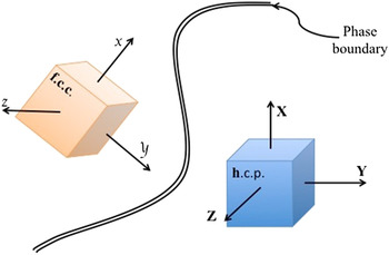
The polycrystalline zircaloy-2 aggregate consists of the hcp matrix and the fcc hydrides. Hence, For 24 slip systems in hcp and 12 slip systems in fcc (Tables I and II), ORs are needed to account for the coherency between the crystalline phases. The lattice parameters of these two phases are such that the (111) fcc plane is identical to the (0001) hcp plane.
Reference Porter, Easterling and Sherif30
When the two crystalline phases are along their close packed planes and directions, the resultant interface is fully coherent. This coherency results in ORs between the two crystalline phases, such that the slip planes and directions are parallel for the systems of
 $\left( {111} \right)_\alpha //\left( {0001} \right)_\kappa$
and
 $\left[ {\bar 110} \right]_\alpha //\left[ {11\bar 20} \right]_\kappa$
, where α denotes a fcc system and κ denotes an hcp system.
Reference Pilania, Thijsse, Hoagland, Lazic, Valone and Liu29,Reference Porter, Easterling and Sherif30,Reference Zhang, Chen, Ren and Kelly41
Based on this, 36 unique ORs can be obtained for the parallel directions and planes between the fcc and hcp phases. Furthermore, the hydride fcc orientations have to be related to the global orientation, and, therefore, two transformations are needed. The first transformation, [T]1, relates the hydride fcc (α) OR to the parent hcp (κ) Euler grain orientations (Table III). The second transformation, [T]2, relates the hcp Euler grain orientation to the global coordinates. These transformations are given by [X]Global = [T]2 [T]1[X]κ.
24 parent slip systems in hcp zircaloy-2.

12 slip systems in fcc.

ORs between fcc (α) and hcp (κ).

To calculate the transformation for the first ORs (Fig. 1), we define two 3 × 3 matrices, which are related to the fcc and hcp parallel slip systems as follows. One matrix, which is the fcc
 ${\left( {111} \right)_\alpha }{\left[ {\bar 101} \right]_\alpha }$
slip system is given by the 3 × 3 fcc matrix related to the
 ${\left( {111} \right)_\alpha }{\left[ {\bar 101} \right]_\alpha }$
slip system as
 $$\left[{\matrix{1 \hfill & {\bar 1} \hfill & 1 \hfill \cr 1 \hfill & 0 \hfill & {\bar 2} \hfill \cr 1 \hfill & 1 \hfill & 1 \hfill \cr}} \right]\quad .$$
Phase boundaries between fcc and hcp

The first column is related to the normal of the plane, the second column is the slip direction, and the third column is the cross product of the first and second columns.
We perform a similar operation for the hcp systems, where we assumed a ratio of c/a = 1.594 because this is a physically realistic value for Zr.
Reference Niewczas42
We then transformed the hexagonal system to a Cartesian system, and we also obtained a 3 × 3 matrix hcp slip system. So for example, slip system
 ${\left( {0001} \right)_\kappa }{\left[ {\bar 2110} \right]_\kappa }$
in the hexagonal system with c/a = 1.594 is (000.6274)κ[100]κ in the Cartesian system (see Ref. Reference Ziaei and Zikry5 for how the hexagonal system is transformed to a Cartesian system).
 $$A = \left[ {\matrix{0 & 1 & 0 \cr 0 & 0 & {0.6274} \cr {0.6274} & 0 & 0 \cr}}\right]\quad .$$
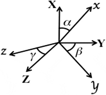
Now to relate the two crystalline phases, we calculate the three angles, for each x, y, z component, between the two crystalline phases (Fig. 2) as
 $$k = \cos \left( {∡{\rm{between}}\,{\rm{f}}{\rm{c}}{\rm{c}}{\rm{.}}/{\rm{h}}{\rm{c}}{\rm{p}}{\rm{.}}\,{\rm{normal}}\,{\rm{planes}}} \right) = 0.3622\quad ,$$
 $$g = \cos \left( {∡{\rm{between}}\,{\rm{f}}{\rm{c}}{\rm{c}}{\rm{./h}}{\rm{c}}{\rm{p}}{\rm{.}}\,{\rm{directions}}} \right) = 0.7071\quad ,$$
 $$n = \cos \left( {∡{\rm{between}}\,{\rm{f}}{\rm{c}}{\rm{c}}./{\rm{h}}{\rm{c}}{\rm{p}}{\rm{.}}\,z\,{\rm{axis}}} \right) = 0.2561\quad .$$
Angles between the fcc and hcp axes, where the lowercase symbols are for the fcc system and the uppercase symbols are for the hcp system.

The fcc phase is then projected to the hcp phase by defining a matrix B as
 $$B = \left[ {\matrix{{0.3622} & { - 0.7071} & {0.2561} \cr {0.3622} & 0 & { - 0.5123} \cr {0.3622} & {0.7071} & {0.2561} \cr} } \right]\quad .$$
The transformation relation between matrix A, the hcp system, and the matrix B, the fcc projection onto the hcp system is then given by
 $$\left[ T \right]_1 = {\rm{transformation}}\,{\rm{matrix}} = B \times A^{ - 1} = \left[ {\matrix{{ - 0.7071} & {0.4082} & {0.5774} \cr 0 & { - 0.4082} & {0.5774} \cr {0.7071} & {0.4082} & {0.5774} \cr} } \right]\quad ,$$
and this is the OR between the
 ${\left( {111} \right)_\alpha }//{\left( {0001} \right)_\kappa }$
and
 ${\left[ {\bar 101} \right]_\alpha }//{\left[ {\bar 2110} \right]_\kappa }$
.
IV. COMPUTATIONAL APPROACH
The total deformation rate tensor D
ij and the plastic deformation rate tensor
 $D_{{\rm{ij}}}^{\rm{p}}$
are needed to update the material stress state. The method used here is that developed by Zikry
Reference Zikry32
for rate-dependent crystalline plasticity formulations, and only a brief outline will be presented here. For quasi-static deformations, an implicit finite element (FE) method with Broyden, Fletcher, Goldfarb, and Shanno iteration is used to obtain the total deformation rate tensor D
ij. To overcome numerical instabilities associated with stiffness, a hybrid explicit–implicit method is used to obtain the plastic deformation rate tensor
 $D_{{\rm{ij}}}^{\rm{p}}$
. This hybrid numerical pattern is also used to update the evolutionary equations for the mobile and immobile densities. The hybrid approach is based on using explicit Runge Kutta, and an implicit Euler method, when numerical stiffness is encountered. Numerical stiffness can be encountered when due to different rate changes along slip systems, slip-rates, resolved shear-stresses, and dislocation-densities can vary widely.
A. Microstructural failure criterion and numerical implementation of overlapping element method
The inherent fracture mode in hcp material would be cleavage fracture on the basal planes. Reference Musienko and Cailletaud43 To account for this as a microstructural failure criterion, the orientation of the cleavage planes for each variant in the global coordinate system is obtained by applying the series of transformations as
 $${n_{{\rm{cleave}}}} = {\left[ T \right]_2}{\left[ T \right]_1}{n_{{\rm{cleave}},\mathop \kappa \limits^\prime }}\quad ,$$
where [T]1 relates the fcc ORs to the parent hcp Euler grain orientation, and the second transformation, [T]2, relates the parent hcp Euler grain orientation to the global coordinates.
The global orientation of the cleavage planes in the current configuration is then obtained by updating, at every time-step, the lattice rotations as
 ${\dot n_{{\rm{cleave}}}} = W{n_{{\rm{cleave}}}}$
. The normal component of the traction acting on each cleavage plane has a direct influence on fracture along that plane.
Reference Musienko and Cailletaud43,Reference Pouillier, Gourgues, Tanguy and Busso44
Therefore, the maximum normal component of the traction on cleavage planes is monitored and compared with a critical fracture stress σfrac to determine failure. The failure criterion is then given by
 $${t_{{\rm{cleave}}}} > {\sigma _{{\rm{frac}}}}\quad ,$$
where
 ${t_{{\rm{cleave}}}} = {\rm{ma}}{{\rm{x}}_{\left( {0001} \right),{\rm{planes}}}}\left\langle {n_{{\rm{cleave}}}^{\rm{T}}\left[ \sigma \right]{n_{{\rm{cleave}}}}} \right\rangle$
.
For the fracture analysis, we want to physically represent the nucleation and propagation of failure surfaces. We follow the approach of Wu and Zikry Reference Wu and Zikry45 and Hansbo and Hansbo, Reference Hansbo and Hansbo46 and consider one element with a crack defined implicitly by f(X) = 0. This divides the element domain into two subdomains with areas A e1 and A e2. The direction of crack propagation would be along the most favorable cleavage plane. Reference Morris47,Reference Wang, Wang, Shi, Hui and Dong48 Adding phantom nodes on top of the existing nodes, the original cracked element is replaced by two overlapping elements. The two overlapping elements do not share nodes and therefore can have independent displacement fields. For each overlapping element, only the subdomain with area A e1 or A e2, corresponding to one of the two subdomains for the original cracked element, is considered as active. Details for the implementation of overlapping element method are given in Wu and Zikry. Reference Wu and Zikry45
V. RESULTS AND DISCUSSION
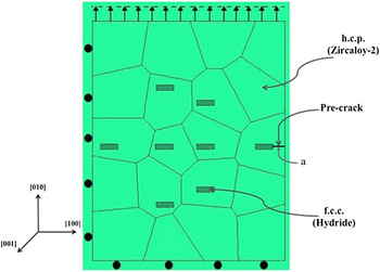
The multiple-slip dislocation-density-based crystal plasticity formulation and the overlap fracture method were used to investigate the microstructural failure behavior of Zircaloy-2. The parent hcp zircaloy-2 grains and the fcc hydrides are assumed to have random low angle misorientations, where the maximum misorientation was assumed to be less than 5°. In this investigation, it is assumed that the hydride volume fraction is approximately 3%, which is physically representative of zircaloys. Reference Alam and Hellwig15,Reference Arsene, Bai and Bompard24,Reference Chen, Li, Zheng, Wang and Lu49,Reference Arsene, Bai and Bompard50 A convergent plane strain FE mesh of 6000 elements, with a model size of 4 mm × 5 mm, with symmetric boundary conditions, was subjected to tensile loading for a dynamic nominal strain rate of 5000 s−1 (Fig. 3). The material properties that are used for zircaloy-2 and the hydrides are given in Tables IV and V. Reference Kubo, Kobayashi and Uchikoshi51–Reference Mareau and Daymond54 For computational purposes, the four-index Miller-Bravais indices of the hexagonal crystallographic planes and directions are recast in terms of a three-index Cartesian coordinate system, and this approach has also been used by Hofmann and Lubarda, Reference Hofman and Lubarda55 Niewczas, Reference Niewczas42 and Ziaei and Zikry. Reference Ziaei and Zikry5
Microstructural model of zircaloy-2 (hcp) and the hydrides (fcc).

Properties of Zircaloy-2.

Properties of the hydrides.

A. Dynamic behavior with no fracture
We investigated the behavior of zircaloy-2 and the hydrides at a strain rate of 5000 s−1 for a case without existing cracks. We wanted to understand how the ORs would affect behavior by examining two cases, one case with ORs and one case without ORs between the coherent hcp zircaloy parent and the fcc hydrides.
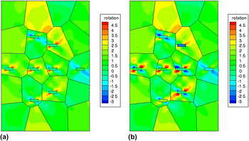
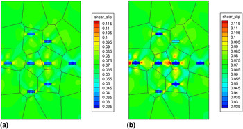
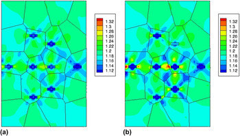
The effects of the ORs can be clearly seen by examining the local behavior through spatial contours. At a nominal strain of 10%, the maximum lattice rotation without ORs was 4.5° and with ORs was 7°, which occurred at the interfaces of the fcc hydrides and the hcp. parent material [Figs. 4(a) and 4(b)]. The accumulated plastic slip due to activity on all the active hcp slip systems, at a nominal strain of 10%, is shown in Figs. 5(a) and 5(b) with and without the ORs. The maximum accumulated slip is 0.16 with the ORs and without the ORs, was 0.12 [Figs. 5(a) and 5(b)]. Almost all the inelastic deformation is in the zircaloy matrix, with the hydrides being essentially brittle as indicated by the insignificant shear slip accumulation. Furthermore, for the ORs case, most of the inelastic accumulation is at the interface of the different crystalline phases, which is consistent with experimental observations. Reference Puls25,Reference Chen, Li, Zheng, Wang and Lu49,Reference Une, Nogita, Ishimoto and Ogata56 The maximum normalized (the temperatures were normalized by the initial room temperature) temperature with OR had a maximum value of 1.47 and without ORs, the maximum was 1.32. [Figs. 6(a) and 6(b)], and these maximum thermal values occurred at the fcc/hcp interfaces. These differences between aggregates with and without ORs are significant, and they underscore the need for the accurate ORs representation of the different crystalline phases and interfaces.
Lattice rotation (a) no ORs (b) with ORs at 10% nominal strain.

Shear slip (a) no ORs (b) with ORs at 10% nominal strain.

Temperature (a) no ORs (b) with ORs at 10% nominal strain.

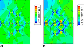
The effects of the ORs can also be clearly seen in the distribution of the normal stresses [Figs. 7(a) and 7(b)]. At a nominal strain of 10%, the maximum normalized (the stresses were normalized by the static yield stress), occurred at the fcc/hcp interfaces with a maximum normalized value of approximately 8. For the case without ORs, in the same locations, the maximum stress value was 5. These effects can also be seen in the distribution of the dislocation-densities [Figs. 8(a) and 8(b)]. At a nominal strain of 10%, with the ORs, the most active immobile dislocation density slip system is the pyramidal
 $\left( {0\bar 111} \right)\left[ {\bar 12\bar 13} \right]$
system. For the case with ORs, the maximum dislocation density is at the fcc/hcp interface, and without the ORs, the dislocation-densities are lower with no accumulation at the interfaces. The dominance of the pyramidal slip system in the system with hydrides is also consistent with experimental observations.
Reference Perovic and Weatherly57,Reference Tournadre, Onimus, Béchade, Gilbon, Cloué, Mardon and Feaugas58
Normal stress (a) no ORs (b) with ORs at 10% nominal strain.

Most active immobile density for pyramidal system
 $\left( {0\bar 111} \right)\left[ {\bar 12\bar 13} \right]$
(a) no ORs (b) with ORs.

B. Dynamic fracture behavior
We then investigated how a crack in an aggregate subjected to a nominal strain-rate of 5000 s−1. We, again, examined two cases, one case with the ORs and one case without the ORs. The crack length was taken as a/w = 0.1, and it is an edge crack as shown in Fig. 3. As noted earlier, the crack is allowed to dynamically propagate when the maximum fracture stress is exceeded on the cleavage basal plane [Eq. (15)].
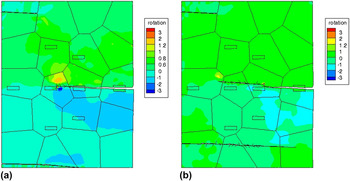
At a nominal strain of 4%, the maximum lattice, with and without the ORs, is shown in Figs. 9(a) and 9(b). As it can be clearly seen, the fracture behavior is different for both cases. For the case with ORs, the propagating crack is nonplanar, and it deviated around the hydrides. Furthermore, cracks also nucleated at the bottom and at the top for both cases, and these cracks nucleate due to the reflecting inelastic waves. For the case without the ORs, the crack is planar, and the lattice rotations were significantly higher by approximately 60%. These higher lattice rotations were due to not physically representing ORs. Furthermore, the deviation of the cracks, for the case with ORs, is consistent with experimental observations pertaining to zircaloys with hydrides that show that cracks deviate around the hydrides. Hence, these results clearly indicate the necessity of accurately accounting for fcc/hcp interfaces.
Lattice rotation at 20% (a) no ORs (b) with ORs at 4% nominal strain.

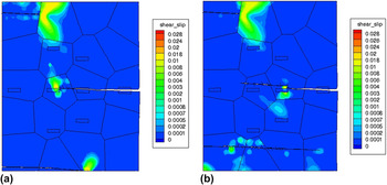
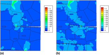
The accumulated plastic slip due to all hcp active slip systems, at a nominal strain of 4%, is shown in Figs. 10(a) and 10(b) with and without the ORs. The maximum accumulated slip was 0.032 with the ORs, and without the ORs, the maximum plastic slip was 0.042. For the temperatures, with the ORs, and the maximum normalized temperature was 1.12 without the ORs [Figs. 11(a) and 11(b)], and these maximum thermal values occurred at the hcp/fcc interfaces.
Shear slip-rate (a) no ORs (b) with ORs at 4% nominal strain.

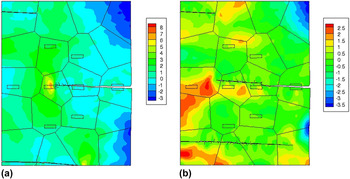
The effects of the ORs can also be clearly seen in the distribution of the normal stresses [Figs. 12(a) and 12(b)]. At a nominal strain of 4%, the maximum normalized stress occurred ahead at the crack front with a maximum normalized value of approximately 4. For the case without ORs, the maximum value was 8 in the same region, which is twice the value of the ORs case. These effects can also be seen in the distribution of the dislocation-densities [Figs. 13(a) and 13(b)]. At a nominal strain of 4%, with the ORs, the most active immobile dislocation density slip system was the pyramidal
 $\left( {0\bar 111} \right)\left[ {\bar 12\bar 13} \right]$
system with a normalized immobile dislocation density of approximately 1700, and this is consistent with the experimental results.
Reference Tournadre, Onimus, Béchade, Gilbon, Cloué, Mardon and Feaugas58,Reference Yoo, Agnew, Morris and Ho59
Without the ORs, the immobile dislocation-densities are lower, and the maximum normalized immobile dislocation density was approximately 1400. These differences in the evolution of the immobile densities at the interfaces were due to the ORs, which clearly affected crack propagation and orientation. For the case with ORs, the cracks deviated around the hydrides, and this results in higher dislocation densities due to the more active and ductile hcp aggregate.
Temperature (a) no ORs (b) with ORs at 4% nominal strain.

Normal stress at (a) no ORs (b) with ORs at 4% nominal strain.

Most active immobile density, pyramidal system
 $\left( {0\bar 111} \right)\left[ {\bar 12\bar 13} \right]$
(a) no ORs (b) with ORs at 4% nominal strain.

VI. CONCLUSION
We have presented a dislocation density based multiple-slip crystal plasticity formulation that accounts for ORs between fcc and hcp systems. We investigated the effects of ORs for an aggregate with and without cracks subjected to dynamic loading conditions. We obtained 36 unique ORs between parallel directions and planes between the relevant fcc and hcp systems. The ORs significantly affected local behavior, in aggregates without cracks, such as shear slip accumulation, dislocation-density evolution, lattice rotation, thermal and stress buildup.
For the case with a preexisting crack, the ORs had a significant effect on crack paths and orientations. The edge crack curved around the hydrides for the aggregate with ORs, and for the cases without ORs, the crack path was planar. This crack deviation and nonplanar behavior were due to the ORs and the higher stresses ahead of the crack front. For the aggregates with ORs, there was higher dislocation-density accumulation along the pyramidal plane due to lattice rotation in comparison with the case without ORs. These crack orientations are also consistent with experimental observations. This study underscores the need to represent the coherency between fcc and hcp interfaces in heterogeneous crystalline systems for accurate predictions of local behavior.
ACKNOWLEDGMENTS
A Support from the Consortium for Advanced Simulation of Light Water Reactors an Energy Innovation Hub for Modeling and Simulation of Nuclear Reactors under U.S. Department of Energy Contract No. DE-AC05-00OR227 and partial support from ARO grant W911NF-12-1-0329 are gratefully acknowledged.