Introduction
In recent years, flexible antennas have gained popularity in wearable communication devices due to their adaptability and simplicity of installation. Flexible antennas work well in a variety of applications, including smart homes, patient tracking, military, and health care monitoring. The substrates of traditional planar antennas, including the FR4, Rogers 3006, and RT Duroid 5880, are rigid and unfitting for wearable applications. These substrates can be replaced by polymers, textiles, carbon nanotube, and microfluidic-based components to create wearable antennas [Reference Chaya Devi, Angadi and Mahesh1–Reference Simorangkir, Kiourti and Esselle7]. These flexible substrates have their own advantages and disadvantages. Polydimethylsiloxane (PDMS) is one of the most widely utilized polymer-based dielectric substrates for wearable antenna due to its flexibility, hydrophobic nature, and altered dielectric property with suitable impurities [Reference Simorangkir, Kiourti and Esselle8–Reference Fu, Lei, Zou and Guo10]. Over the years, several types of materials have been used to create the conductive layers on the PDMS. Copper plates, metal-based, graphene-based, conductive silicones, and indium tin oxide nanoparticles are employed as conductive layers, and there has been substantial research into how to increase the adhesion between the PDMS and the conducting layers [Reference Elmobarak, Rahim, Abedian, Soh, Vandenbosch and Lo11–Reference Khan, Ali, Bae and Lee13].
The primary goal of any wearable antenna design is to minimize the effects of antenna radiation on the human body while maintaining the basic antenna parameters. The radiated energy absorbed by the body is specified in terms of specific absorption rate (SAR) and it should be maintained within an acceptable limit. Each nation adheres to its own SAR guidelines. According to FCC regulations, SAR values under 1.6 W/kg over a volume of 1 g of tissue are permitted in India and the USA. European nations are permitted to use SAR value of 2 W/kg over tissues weighing less than 10 g in accordance with the International Electrotechnical Commission (IEC) standards.
Meta-surfaces have been effective for enhancing gain by either absorbing energy in a certain direction or reflecting energy due to their unique properties. A number of attempts have been made in recent years to incorporate these metasurface (MS) based structures, such as artificial magnetic conductors, electromagnetic band gap structures, partial reflecting surfaces, and frequency-selective surfaces to redirect backward radiation of antennas [Reference Abirami and Sundarsingh14–Reference Najumunnisa, Sastry, Madhav, Das, Hussain, Ali and Aslam27]. The metamaterial acts as a filter at the designed frequency. The backward radiation from the antenna is redirected by the MS, which eventually reduces the energy absorption by the body thus scaling down the SAR value. The presence of MS also improves the gain performance of the antenna. The proposed work consists of a flexible unique geometry antenna with PDMS substrate and copper conductors integrated with a metamaterial of same substrate for gain enhancement and SAR reduction.
Metamaterial antenna design
The geometry of the proposed metamaterial integrated monopole antenna is shown in Fig. 1. The antenna consists of two layers with one layer as radiator and the second layer is 2 × 2 array of metamaterial. The antenna and the metamaterial are fabricated on a 1 mm-thick flexible and hydrophobic PDMS substrate of a dielectric permittivity of 2.7 and a loss tangent of 0.0314. The conducting layer of the antenna and the metamaterial is a 0.035 mm-thick copper foil. The proposed radiator is coined from the alphabets “K”, “I”, and “T” indicating the institute name. The angle of K is kept at 60° with a depth of 0.5 L 1. The antenna has a partial ground plane below the dielectric substrate. Lateral dimension of the radiating element is 0.253λ 0 × 0.144λ 0 at 2.45 GHz. Total length of the radiator is quarter wavelength at 2.45 GHz frequency. Unit cell of dual-sided metamaterial consists of an open square ring top and a thin strip at the bottom of the dielectric substrate. Period of the metamaterial unit cell is 24.5 mm. The overall dimension of the proposed metamaterial antenna is 49 × 49 × 19 mm3. Dimensions of the proposed antenna after parametric optimization are listed in Table 1.
Proposed antenna structure. (a) Antenna with metamaterial. (b) Top and bottom view of antenna geometry. (c) Top and bottom view of metamaterial unit cell. (d) Side view.

Antenna geometric parameters

Geometrical optimization of antenna
The designed antenna is simulated and optimized using Ansys HFSS 2022 electromagnetic software. Understanding the influence of the antenna's geometrical parameters on its performance is typically aided by the parametric analysis. The application and the performance of the antenna depend on the operating frequency, which is mainly influenced by the geometry of the antenna. The reflection performance of the antenna indicating return loss versus frequency curve can be optimized for a particular geometry with a parametric study. In this case, length and width of the radiating strip and ground are optimized to operate at 2.45 GHz frequency. This section presents the study of the effect of frequency variation in return loss performance for various geometric parameters of the proposed antenna. Figures 2–7 depict the result of optimized geometric parameters. As L, the base length of K, increases, the resonance frequency decreases, and at L = 7 mm, return loss is maximum at a designed frequency of 2.45 GHz. Height of K is represented by L 1, whose resonance increases and decreases with an increase in the value of L 1. Optimal height is at L 1 = 7 mm with a return loss of 40 dB at 2.45 GHz. The spacing between K and I is L 2 and the return loss is good for L 2 = 4 mm. The length of T and K is maintained uniformly at 7 mm. The width of the strip is varied from 1mm to 3mm in steps of 0.5 mm. s = 2 mm shows return loss maximum at 2.45 GHz. Feed length Lf and ground length Lg are optimized to 7 and 6.5 mm, respectively. The antenna performance for conformal placement is also verified by bending the antenna along x and y direction with bend radii r and r 1 varying from 50 to 100 mm as depicted in Figs 8 and 9. Bending of antenna along both axes does not affect the reflection performance of the antenna indicating its flexibility and conformal nature. All parametric studies are done by strictly keeping the remaining parameters constant in accordance with the dimensions in Table 1. Figure 10 shows the VSWR performance of the proposed antenna. The VSWR value at designed frequency is 1.39:1.
Effect of S 11 performance for varying length L.

Effect of S 11 performance for varying length L 1.

Effect of S 11 performance for varying length L 2.

Effect of S 11 performance for varying strip width s.

Effect of S 11 performance for varying feed length Lf.

Effect of S 11 performance for varying feed width wf.

Effect of S 11 performance for varying bend radius r along x direction.

Effect of S 11 performance for varying bend radius r 1 along y direction.

VSWR performance of the proposed antenna.

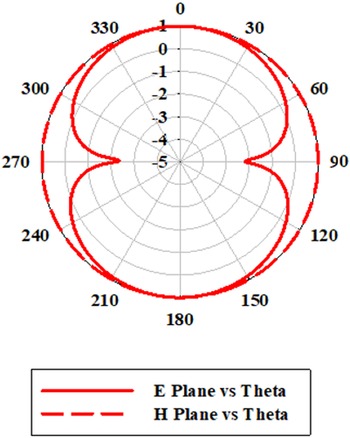
Simulated radiation performance of the proposed antenna in E- and H-planes is plotted in Fig. 11. The E-plane pattern at a designed frequency shows the figure of 8 pattern while the H-plane is omnidirectional. The antenna gain is plotted in Fig. 12. Peak gain of the antenna is 1.88 dBi at 2.415 GHz, and at 2.45 GHz the gain is 1.874 dBi. The SAR value of the antenna analyzed with an arm phantom model is 7.13, 5.62, and 3.07 W/kg, respectively, at 2, 5, and 10 mm from the hand phantom model. The antenna gain and SAR performance are improved using a dual-sided MS discussed in the following sections.
E- and H-plane radiation performance of the proposed antenna.

Gain performance of the proposed antenna.

Metamaterial unit cell
The metamaterial unit cell consists of a square split ring and a metal strip printed on the top and bottom of a PDMS substrate of thickness 1 mm as shown in Fig. 1c. The simulation setup of the metamaterial unit cell is shown in Fig. 13. Simulation is done by assigning proper boundary condition with perfect E and H on opposite faces along x and y axes. Excitation to the unit cell is provided using Floquet port mode on opposite sides along z-axis. S parameters in terms S 11 and S 21 at ports 1 and 2 are analyzed in terms of magnitude and phase.
Simulation setup of designed unit cell.

The period of the unit cell is 24.5 mm. The design parameters of the proposed unit cell are included in Table 1. Magnitude and phase response of reflection and transmission performance of the metamaterial unit cell are shown in Figs 14 and 15. The permittivity and permeability of the metamaterial unit cell are extracted from S parameters using Matlab code. Extracted impedance, refractive index, permittivity, and permeability of the proposed unit cell in real and imaginary forms are plotted in Figs 16–19. The plots indicate the negative reflection property of MS.
Unit cell S parameter magnitude.

Unit cell S parameter phase.

Real permittivity and permeability.

Imaginary permittivity and permeability.

Real impedance and refractive index.

Imaginary impedance and refractive index.

Antenna with metamaterial
Proposed KIT monopole antenna has back radiation which increases the SAR value. Placing an MS at appropriate distance from the antenna can improve the gain performance of the antenna while minimizing the SAR. The antenna is placed above the MS supported by foam which has a dielectric permittivity closer to air. Height between the antenna and MS is optimized to have maximum gain.
Figure 20 shows the antenna placed on the male right arm. When the antenna is placed on the body, the resonance shifted due to variation in dielectric of the body. Return loss performance of the antenna is optimized by varying the height between the antenna and the metamaterial. The antenna performance with various array combinations of metamaterial unit cells like 2 × 1, 2 × 2, and 2 × 3 elements as in Fig. 21 is also analyzed.
Proposed antenna on the arm.

Antenna with metamaterial arrays (a) 2 × 1 array, (b) 2 × 2 array, (c) 2 × 3 array.

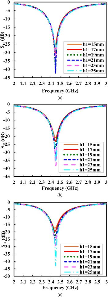
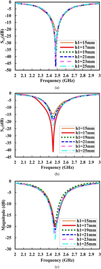
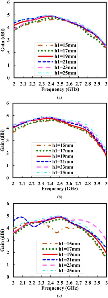
Simulations are carried with h 1 varying from 1 to 25 mm, and show good return loss performance below 10 mm in all three array combinations, but the SAR performance was better only above 17 mm spacing. Thus, S 11 performance graphs are plotted with different arrays of the metamaterial with the antenna on and off body as shown in Figs 22 and 23. The on body antenna return loss with the metamaterial for 2 × 1, 2 × 2, and 2 × 3 arrays are maximum at h 1 = 21, 23, and 25 mm, respectively, below −10 dB reference. In off body condition, maximum return loss is obtained for h 1 = 21, 17, and 25 mm for 2 × 1, 2 × 2, and 2 × 3 unit cell arrays. On body gain of the antenna with metamaterial arrays are plotted in Fig. 24. The gain increases with the number of metamaterial unit cells. Gain maximum at a designed frequency of 2.45 GHz is 4.87 dBi at h 1 = 24 mm for 2 × 1 array, 4.84 dBi at h 1 = 25 mm for 2 × 2 array, and 4.97 dBi at h 1 = 25 mm for 2 × 3 array metamaterial surface inferring maximum gain is obtained for larger size metamaterial array. Maximum peak gain is 4.986 dBi and is obtained for 2 × 3 array at a distance h 1 = 25 mm at a frequency of 2.48 GHz. Gain of antenna at 17 mm height is 4.73, 4.61, and 4.64, respectively, for 2 × 1, 2 × 2, and 2 × 3 array unit cell combinations.
Effects on S 11 performance with various array combinations of metamaterial antenna on body (a) 2 × 1 array, (b) 2 × 2 array, (c) 2 × 3 array.

Effects on S 11 performance with various array combinations of metamaterial antenna off body (a) 2 × 1 array, (b) 2 × 2 array, (c) 2 × 3 array.

On body gain performance of antenna with various array combinations of metamaterial unit cell (a) 2 × 1 array, (b) 2 × 2 array, (c) 2 × 3 array

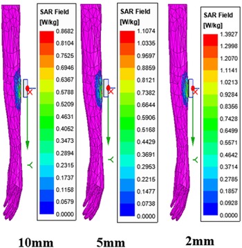
The biomedical application of any antenna requires lower SAR performance. Thus, SAR analysis is done with different metamaterial array antennas at different h 1 values with 100 mW as input power and 2 mm spacing from the body on male arm and the results are tabulated in Table 2. At 17 mm height, the SAR performance for 2 × 2 array metamaterial is below the acceptable level of 1.6 W/kg. The SAR is also tested by placing the antenna at 2, 5, and 10mm spacing from the body as in Fig. 25. The obtained SAR values are 1.392, 1.107, and 0.868 W/kg, respectively, for 2, 5, and 10 mm and are less than the acceptable SAR of 1.6 W/kg.
SAR performance of the 17 mm height 2 × 2 array metamaterial antenna at different spacing from the male right arm.

SAR performance of proposed antenna

Considering gain, return loss, and SAR performance of the antenna, the optimal one is with 2 × 2 array metamaterial placed at 17 mm spacing. The optimization is further performed and the resonance is achieved at L 1 = 6.82 mm which is depicted in Fig. 26.
Effects on S 11 performance for varying length L.

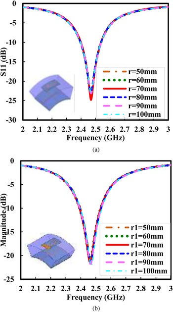
Bending analysis is performed for the metamaterial antenna with 17 mm foam as a spacer between the metamaterial and the antenna. Magnitude plots with different radii from 50 to 100 mm along x and y directions are shown in Figs 27(a) and (b) and indicate that bending of the antenna does not affect the stability performance and is flexibly suited for wearable application.
Effect of S 11 performance for varying bend radius r and r 1 (a) r along x–axis, (b) r 1 along y-axis.

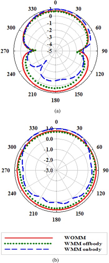
Radiation patterns of the antenna in E- and H-planes with and without metamaterial placed on and off body are simulated and plotted in Figs 28(a) and (b). E-plane patterns of the antenna without metamaterial is bidirectional and with metamaterial the back lobe is reduced in on and off body condition. Maximum reduction of 8 dB in the back lobe is shown in on body due to dielectric variation. The H-plane shows omni patterns with a smaller change in the on body performance.
Simulated radiation patterns of antenna with and without metamaterial (a) E–plane. (b) H-plane.

Fabrication and measurement setup
The antenna with optimal dimension is fabricated by initially preparing a PDMS substrate of required dimension. The metallic layer of the antenna and MS is extracted separately as Gerber file or dxf file and the PCB layout is created to enable wire cutting. Copper foils of required geometry and size are cut using an electric wire cutting machine of high precision and glued to the PDMS to get the required metamaterial antenna geometry. The PDMS layer is prepared by combining Sylgard 184 silicon elastomers base and curing agent in the portion of 10:1 ratio. The air bubbles of the liquid PDMS are removed by vacuum desiccation and poured in a glass mold of required size. The PDMS gel is constantly rotated to make even distribution in the mold and placed in the oven for slow annealing for 8–10 hours at a temperature of 50 °C. If air gaps and misalignment are not prevented throughout the process, the antenna's performance may be negatively impacted, hence utmost care is taken for antenna fabrication utilizing PDMS substrate.
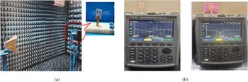
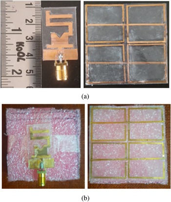
The reflection performance of the antenna is measured using network analyzer and the radiation performance in terms of pattern and gain is measured using standard horn antenna in an anechoic chamber of size 5 × 3 × 2.6 mm3. The horn antenna is a double-ridge broadband antenna operating upto 18 GHz. The test antenna is placed on a turn table capable of rotating in 360֯° and capable of moving in horizontal and vertical directions. Figure 29(a) shows the measuring setup of the antenna in anechoic chamber and Fig. 29(b) the vector network analyzer. Photograph of the fabricated prototype of the antenna with 2 × 2 array of metamaterial unit cell is shown in Figs 30(a) and (b). Gain of the antenna is measured using Friis transmission equation.
Measuring setup of the antenna. (a) Anechoic chamber. (b) Network analyzer.

Fabricated antenna prototype with metamaterial. (a) Antenna and metamaterial without foam. (b) Top and bottom of metamaterial antenna with foam spacer.

Results and discussion
The simulated results are compared with the measured results for validation. Figure 31 depicts the comparative results of return loss of the proposed antenna. The measured antenna resonates at 2.42 GHz with a return loss of 21.93 dB while the simulated return loss is 40 dB at 2.45 GHz. The antenna when placed at a height of 17 mm from the metamaterial with foam in between shows a shift in resonance with S 11 magnitude as −45.3 dB at 2.4 GHz frequency during measurement and −35.45 dB at 2.48 GHz on simulation.
Simulated and measured off body return loss of the proposed antenna with and without metamaterial.

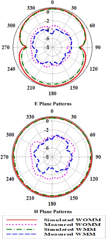
Measured radiation patterns in E- and H-planes at 2.45 GHz are plotted in Fig. 32. E-plane pattern shows the figure of 8 pattern and the H-plane has an omni pattern with radiation distributed equally in all directions. Gain of the antenna with and without metamaterial is plotted in Fig. 33. Gain of the antenna with metamaterial is 4.61 dBi during simulation and 4.38 dBi during measurement at the designed frequency of 2.45 GHz. Thus, the use of metamaterial has an improvement of 40.1% gain from 1.88 dBi of basic KIT monopole. Comparative performance of the antenna with few existing similar antennae is tabulated in Table 3. The proposed antenna shows lower SAR and considerable gain with smaller lateral cross-section.
Simulated and measured off body radiation patterns of the antenna with and without metamaterial.

Simulated and measured off body gain performance of the proposed antenna with and without metamaterial.

Performance comparison of proposed antenna with existing literature

Conclusion
The designed monopole antenna has a unique geometry coined with alphabets K, I, and T. The antenna is fabricated on a 1 mm thick PDMS substrate of lateral dimension 31 × 17.64 mm2. The antenna resonates at 2.45 GHz with a return loss of 40 dB and gain 1.88 dBi, but with higher SAR value of 7.13 W/kg. The SAR value is reduced with a 2 × 2 array MS of period 24 mm below the antenna at 17 mm spacing. MS improved the SAR and gain performance of the antenna. Obtained gain is 4.61 dBi with SAR reduced to 0.868 W/kg at 10 mm from the body. The proposed antenna is a good choice for biomedical application.
Acknowledgement
This work is funded by All India Council for Technical Education, under research promotion scheme. File No.8-122/FDC/RPS/POLICY-1/2021-2022. The authors acknowledge RF laboratory, Karunya University for fabrication.
Competing interest
The authors declare none.
 K. Ramasamy was born in Sivakasi, India, on 10 March 1966. He obtained B.E. in electronics and communication engineering from Madurai Kamaraj University, India, an M.E. in applied electronics from Bharathiar University, India, and a Ph.D. in communication engineering from Multimedia University, Malaysia, in 1988, 1993, and 2006, respectively. He is a senior member of IEEE, fellow in IETE, nominee member in CSI, and a member in ISTE. He has more than 34 years of experience in academics and administration in different engineering colleges in India and abroad. Currently, he is working as a professor and dean (academics and research) in KalaignarKarunanidhi Institute of Technology, Coimbatore since December 2019. He has published more than 150 papers in international journals and conferences. His research interests include error-correcting codes, design of microstrip patch antenna, and wireless communications. He guided three Ph.D. scholars. He visited many countries such as Malaysia, Singapore, Oman, Kuwait, Qatar, Dubai, Italy, UK, etc. He is a recipient of National Merit Scholarship Award by the Government of India, and EMC2 Academic Leader Award 2015. He is also awarded the silver medal in KERIE 2006, conducted by the Faculty of Engineering, International Islamic University Malaysia, for the best Ph.D. work “Asymmetric Turbo Code for Enhanced Performance of JPEG Coded Image Transmission over 3 G Systems.”
 B. A. Sapna obtained her B.E. in electronics and communication engineering from Madras University, India in 2000, an M.E. in communication systems from Anna University, India in 2007, and a Ph.D. in electronics and communication engineering from Anna University, Chennai, India in 2022. Currently, she is working as an assistant professor at KIT-KalaignarKarunanidhi Institute of Technology, Coimbatore, India. She is a life member of ISTE. Her research interests include microstrip antenna, UWB antenna, wearable antennas, frequency-selective surface (FSS), and metamaterials.
 M. Jayasheela obtained her B.E. in electronics and communication engineering from Bharathiar University in 1995. She obtained her Master's degree in communication systems from Anna University, Chennai in 2005. She obtained her Ph.D. in the Department of Electronics and Communication Engineering, from Anna University, Chennai during the year 2014. She worked as a quality engineer in Vee-Jay Lakshmi Engineering Works Ltd, Coimbatore from1995 to1997. She then worked as a lecturer/assistant professor from 1997 to 1998 and from 2002 to 2006 in Electronics and Communication Engineering Department of Karunya Institute of Technology and Sciences, Coimbatore, India. She worked as an associate professor in the Department of Electronics and Communication Engineering, SNS College of Technology, Coimbatore from 2007 to 2013. Presently, she is working as a professor in the Department of Electronics and Communication Engineering at KIT-KalaignarKarunanidhi Institute of Technology. Her fields of interest include antenna and design, signal processing, body area network, mobile communication, wireless cognitive radio, and satellite navigation. She has published several research papers in reputed international journals, presented papers in conferences and filed patent. She is guiding seven Ph.D. scholars. She is a life member of ISTE, IEICE, and IAENG Society of Wireless Networks.