1. Introduction
Cable-driven parallel robots (CDPRs) utilize cables instead of conventional rigid links to control the end-effector (EE) position, which is a moving platform (MP), serving as the orthosis in rehabilitation applications. CDPRs provide numerous advantages over traditional serial and parallel robots. These advantages include reduced weight and inertia, extended operational distances, high-speed motion capabilities, modular geometry, reconfigurability, and heightened dynamics [Reference Tang1, Reference Lamine, Romdhane, Saafi and Bennour2]. CDPRs are classified as over-constrained (m>n) when the number of cables (m) exceeds the degrees of freedom (DOF) (n) of the EE with respect to the base [Reference Zarebidoki, Dhupia and Xu3]. A primary limitation of CDPRs derives from the unilateral nature of cables, necessitating to be constantly kept under tension, allowing only pulling actions and requiring redundant actuation for full constraint [Reference Qian, Zi, Shang and Xu4]. CDPRs offer major advantages [Reference Idà and Mattioni5–Reference Zhang, Shao and Wang8]. Therefore, CDPRs have been employed in medical rehabilitation [Reference Zeghloul, Laribi and Gazeau9–Reference Venkata Sai Prathyush, Ceccarelli and Russo11]. In the field of rehabilitation, cable-driven actuation has been successfully utilized in various robots such as CAREX [Reference Mao and Agrawal12]. CDPRs emerge as promising tools for assisting individuals in rehabilitation following injuries, strokes, neurological disorders, or other medical conditions. These robots facilitate targeted physical exercises to restore muscular function and mobility. Specifically, functional rehabilitation tasks for the legs contribute to improving strength, flexibility, balance, and coordination post-injury or surgery ensuring effective and targeted rehabilitation exercises tailored to individual patient needs [Reference Shoaib, Asadi, Cheong and Bab-Hadiashar13]. CDPRs employ distinct control strategies, as highlighted in ref. [Reference Shoaib, Asadi, Cheong and Bab-Hadiashar13], aiming to minimize complexity and cost by focusing on a limited number of controlled DOFs.
The principal limitation of CDPRs is their low accuracy. There are many approaches in the literature to overcome this drawback. Creating an accurate CDPR model is challenging due to the flexible nature of cables, which necessitates accounting for other factors such as elongation pulley kinematics and cable sag [Reference Riehl, Gouttefarde, Krut, Baradat and Pierrot14]. Although the encoder provides feedback on joint movement, the use of direct kinematic model (DKM) was avoided in refs. [Reference Zake, Chaumette, Pedemonte and Caro15, Reference Zake, Chaumette, Pedemonte and Caro16] by roughly estimating the MP pose. The flexible nature of the cables in the CDPR control system presents a significant challenge, as they can only apply one tensile force. This flexibility makes it more complex to control MP position, which results in reduced accuracy [Reference Jung, Piao, Park, Park and Ko17]. Due to cable slackness, the encoder feedback is not sufficient to determine the MP position, when cables lose tension, they fail to generate the intended MP movement. Consequently, the error in estimating the MP pose increases, and the precision of its estimation is dependent on the slackness of the cables. This is equally applicable to the DKM calculation based on cable length for a simplified CDPR model as in ref. [Reference Ramadour, Chaumette and Merlet18].
Existing CDRRs targeting rehabilitation movements are investigated with respect to control scheme strategy, actuator type, controllers, and sensors [Reference Shoaib, Asadi, Cheong and Bab-Hadiashar13]. CDPR control strategy can be classified according to joint space or workspace, dynamic or inverse kinematics (IK), as well as trajectory planning. Controller performance is generally evaluated in the literature on the basis of Cartesian error for workspace tracking, position tracking error, or joint angle tracking error. The principal control strategy employed to control CDRRs is the task space, which refers to the MP’s pose and orientation in Cartesian space [Reference Shoaib, Asadi, Cheong and Bab-Hadiashar13].
To achieve a good control process, the researchers explored various control systems and robots in the literature [Reference Kong, Tian, Qiu, Wu and Yu20] to understand specific robot parameters. For instance, angular sensors can measure the cable angle [Reference Kong, Tian, Qiu, Wu and Yu20]. Additionally, color sensors can detect color marks on cables, enhancing the accuracy to determine cable length [Reference Do, Choi, Park and Kyung21]. Cable tension sensors determine the center of gravity and can evaluate the current payload mass [Reference Miller, van den Berg, Fritz, Darrell, Goldberg and Abbeel22]. Inertial Measurement Units to estimate Cartesian velocity of the MP [Reference Begey, Cuvillon, Lesellier, Gouttefarde and Gangloff23]. During the design of automated systems, the implementation of vision systems is increasing, given its role as an effective source of information, as noted in ref. [Reference Martinez-Martin and del Pobil24]. Using vision-based data correctly, the camera identifies, localizes, and computes position of any object, and responds to accomplish its tasks [Reference Garcia-Fidalgo and Ortiz25]. Many CDPR systems are controlled via visual servoing [Reference Zake, Chaumette, Pedemonte and Caro16, Reference Bayani, Masouleh and Kalhor26, Reference Pramujati, Syamlan, Nurahmi and Tamara27]. For example, in ref. [Reference Kemp and Edsinger28], four cameras are utilized to accurately determine the MP pose of the CDPR. In addition, extra pairs of stereo cameras were employed to monitor cable sag at their exit points from the CDPR base structure. Another study employed a system of six infrared cameras to identify the position of MP [Reference Edsinger29].
The researchers opted to use a depth camera to obtain 3D data on the environment. Among various depth cameras commercially accessible, Microsoft Kinect [Reference Pop, Ulinici, Pisla, Carbone and Nysibalieva30, Reference Melchiorre, Scimmi, Mauro and Pastorelli31], RGB depth camera [Reference Cio, Raison, Leblond Menard and Achiche32], and RealSense [Reference Jia33, Reference You, Sukkar, Fitch, Karkee and Davidson34] are mostly used and utilized by the researchers. These devices combine data from depth information with 2D RGB image, resulting in the generation of a depth map. Recent studies have explored the metrological characterization of depth cameras [Reference Lachat35], including comparative studies evaluating accuracy and precision [Reference Lourenço and Araujo36]. These studies utilized depth cameras and focused on assessing their resolution, frame rate, and range performances [Reference Lachat35, Reference Lourenço and Araujo36]. A recent study stated that, while many instrumented solutions offer good performances, they are expensive and often restricted to specialist assessment centers, which limits their applicability in large-scale clinical trials [Reference Siena, Byrom, Watts and Breedon37]. Consequently, Intel RealSense is preferred as it presents a good tradeoff between cost and efficacy [Reference Siena, Byrom, Watts and Breedon37]. This camera is used in applications requiring high frame rates with compact size and is a budget-friendly 3D coordinate measurement system, characterized by large acquisition volumes and low costs [Reference Siena, Byrom, Watts and Breedon37].
The aim of this work is to propose a visual servoing algorithm that deals with forward kinematic. Unlike other approaches in the literature, the proposed algorithm is based on tracking the MP’s Cartesian pose and not on complex modeling of the cable [Reference Dallej, Gouttefarde, Andreff, Dahmouche and Martinet38]. This study presents the development of closed-loop camera-based position control system for our CDPR prototype [Reference Ghrairi39] designed for functional rehabilitation tasks using a Depth Camera. Acknowledging the findings of the mentioned studies, Intel RealSense is employed for motion tracking as well as CDPR control correction. Three trajectories are selected, a comparison between desired and actual trajectories is carried out, as well as error analysis of the results. This document is structured as follows: Section 2 delves into CDPR modeling, presents the IK problem, and introduces three different trajectories. Section 3 describes the controller design containing open-loop and closed-loop control systems, and introduces a motion tracking system for MP movements via IntelRealsense. Section 4 details the process of tracking algorithm utilizing the depth camera as well as the control algorithm. Finally, Section 5, results and discussions, presents the experimental outcomes of joint control system, as well as, the experimental and analysis results of Cartesian trajectories for both control strategies applied on the control system before and after PD correction.
Structure of our cable-driven parallel robot.

2. Kinematic control of CDPR
2.1. Kinematic model
CDPRs are comprised of an MP with dimensions c ×d and a base frame with dimensions h ×w, with embedded actuators. These actuators are connected to an MP through four cables. The Cartesian position and orientation of the MP are controlled by adjusting the cable lengths exiting the pulleys. The geometric model CDPR involves four servomotors mounted at the corners of a vertical surface on the robot’s chassis.
 $\mathcal{F}_{0}$
{O,
x
0
,y
0
,z
0
}: Fixed frame of the planar CDPR centered on the four motors, with the horizontal x
0
-axis and the vertical y
0
-axis. C: Exit point of the cable from the pulley. M: Center of the pulley. G: Center of the MP, b: The vector represents the Cartesian position of the center of MP in the frame
 $\mathcal{F}_{0}$
, this parameter depends on the movement executed by the MP.
 $\boldsymbol{\theta }$
: The angle at point M between the horizontal axis and the direction vector from M to point C.
 $\boldsymbol{\rho }$
: Vector between the center of the pulley M and its corresponding corner B of the MP.
 ${\boldsymbol{a}}_\boldsymbol{i}^{T}=\left[\begin{array}{cc} \frac{w}{2} & \frac{h}{2} \end{array}\right]$
for i = 1, The vector defines the center of the pulley in the fixed frame
 $\mathcal{F}_{0}$
.
 $\boldsymbol{R}_{\boldsymbol{\alpha }}$
: The rotation matrix represents the orientation, denoted by α, of the MP in the fixed frame
 $\mathcal{F}_{0}$
.
 $\boldsymbol{r}_\boldsymbol{i}^{T}=\left[\begin{array}{cc} \frac{-c}{2} & \frac{-d}{2} \end{array}\right]$
: Vector between G the center of the MP to the corresponding corner B.
Figure 1 illustrates the kinematic model of our planar cable robot. Equation (1) is applied to calculate the distance
 $\| \boldsymbol{\rho }_\boldsymbol{i}\|$
between the center of the pulley and the cable attachment point on the MP:
 \begin{align} \left\| \boldsymbol{\rho}_\boldsymbol{i}\right\| ^{2}=\left\| \textbf{a}+ \textbf{b} + {\textbf{R}_{\boldsymbol{\alpha}}\textbf{r}_{\textbf{i}}}\right\| ^{2} \\[-25pt] \nonumber \end{align}
The cable winds around the pulley with a radius
 $r$
and exits from point C. By neglecting the diameter of the cable relative to that of the pulley, we assume in the subsequent discussions that
 $r$
is the effective radius, including both the actual radius of the pulley and the cable. The cable departs from the pulley at point C, and the angle between vector from M to C and the horizontal is denoted as
 $\theta$
. Referring to Figure 1, the total length of the cable, accounting for the stretched part
 $L_{S}$
and the part wound on the pulley
 $L_{P}$
, is expressed as follows in Equation (2):
 \begin{align} L=L_{S}+L_{P}=L_{S}+r\theta \end{align}
where
 $r$
is the radius of the pulley, as illustrated in the figure.
 $\theta$
is the angle where the cable is wound around the pulley.
 $L_{S}$
is the stretched part of the cable starting from point C to point B. Taking into consideration the two right-angled triangles, we can calculate the length through Equation (3):
 \begin{align} {L_{S}}^{2}={\boldsymbol{\rho }_\boldsymbol{i}}^{2}-r^{2} \end{align}
where
 $\boldsymbol{\rho }^{T}=[\rho _{x} \rho _{y}]$
,
 $\rho _{x}, \rho _{y}$
are the vector
 $\boldsymbol{\rho }$
coordinates with respect to frame
 $\mathcal{F}_{0}$
. To solve the IK, to determine the angle
 $\beta_{u}$
we consider the tetragonal CMDB, noting that two angles at points C and D of the tetragonal are right angles, we can conclude that the desired complementary angle
 $\beta _{u}$
at point M is equal to the enclosed angle
 $\beta _{1}+\beta _{2}$
at point B. Using elementary trigonometric functions, we obtain Equation (4):

To determine the rate of change of the motor angle with respect to time, it is necessary to calculate the variation in length of each cable as a function of time. This rate corresponds to the servomotor angle variation for each actuator, and it is derived from the variation in the position of the MP over time, using Equation (5).
 \begin{align} V=\dot{L}= \frac{dL}{dt} \end{align}
2.2. Trajectory
In order to assess the performance of the control method, three desired trajectories describing typical kinematic applications were generated. The trajectories consist of:
-
• Circle Movement: The center of the circle coincides with the planar CDPR center, with a radius of 50 cm. Equation (6) is applied to calculate the variation in cable length over time with a radius
 $\psi$
and frequency
$\omega$
.
-
• Square Movement: Four vertical and horizontal displacements extend linearly over 1000mm, over a square of a 25 cm width, passing through the points A (50, 50, 0), B (−50, 50, 0), C (−50, −50, 0), and D (50, −50, 0) in the fixed frame
$\mathcal{F}_{0}$
. Equation (7) is applied for each displacement. -
• Triangle Movement: Three linear movements over an equilateral triangle, passing through the points E (50, 0), F (50cos(2π/3), 50cos(2π/3)), and G (50cos(−2π/3), 50cos(−2π/3)) in the fixed frame
$\mathcal{F}_{0}$
.


For linear motions in the triangle and square movements, Equation (7) is utilized, with
 $\eta$
and
 $\mu$
representing the velocity along the x and y axes, respectively.

 \begin{align} \textbf{X}^{T}=\left[\begin{array}{c@{\quad}c@{\quad}c} X_{p1}+\eta t & Y_{p1}+\mu t & 0 \end{array}\right] \end{align}
3. System overview
3.1. CDPR prototype
Figure 2 illustrates our CDPR prototype configured such that all cable exit points are positioned at the four corners of the fixed platform. Cables in this study are supposed to be rigid and massless. The robot frame is a 2.1 m × 1.7 m rectangle. The size of the MP is 0.2 m × 0.2 m. A depth camera is positioned 2.5 m in front of the MP and CDPR plane. To simplify the vision part, two AprilTags are placed as objects on MP and the reference frame. An algorithm was developed for AprilTags recognition and localization, allowing the robot to be controlled by tracking MP through a depth camera.
Cable-driven parallel robot prototype located at ENISO, Sousse. The components are: (1): Pulley mounted on the Servomotor, (2): Cables, (3): AprilTag attached to the Moving Platform, (4): AprilTag attached to the Fixed frame.

3.2. CDPR prototype control system
Figure 3 shows the hardware architecture of the CDPR control system. A programmable logic controller (PLC) with high-speed pulse output and supporting four hardware 200 kHz high-speed counters is used. This PLC controls the servomotors using a Proportional-Derivative (PD) control. Kinematic data are computed on a PC and then transmitted to the PLC, which commands the actuators based on the desired position and velocity. Each actuation chain, from the servomotors to the cables, has its own controller that takes desired and measured motor position and velocity as input. The output is the corresponding desired motor torque. Each cable will be driven by a servomotor. The specification of the servomotor and encoder is shown in Table I below.
Characteristics of the actuators.

3.3. Motion tracking system
This research aims to implement a tracking system that covers the robot’s workspace as well as the movements performed by the mobile platform. The RealSense D435i, a depth camera widely utilized in current applications, is employed for data collection. During this process, both RGB and depth images are acquired simultaneously. D435i offers stereo depth resolution up to 1280 × 720@90 fps and depth field of view 87° × 58°, in a range from 0.2 m to over 3 m, which varies with lighting conditions. It is also proficient in capturing RGB frames with resolution up to 1920 × 1080@30 fps and RGB field of view 69° × 42°. The camera is well-suited to the dimensions of our robot, exhibiting an root mean square error (RMSE) subpixel depth error of less than 0.12 pixels [Reference Sonoda, Sweetser and Khuong40].
The hardware architecture of the cable-driven parallel robot control system.

After capturing depth maps and color images from each frame, the subsequent step involves calculating their 3D point clouds and aligning them. Various methods are available for this purpose. In our case, we found it adequate to rotate the point cloud data from both RGB and depth images using a 3D transform that would both rotate and shift the point clouds, creating one large composite point cloud.
AprilTag, introduced in 2011 by Olson [Reference Olson41], is a robust and adaptable visual fiducial system. It employs a 2D code style, as illustrated in Figure 4, facilitating full 6-DOF feature localization from an image. The system comprises two primary components: the coding system and the tag detector. The tag detector’s function is to identify potential tag positions in the image using a graph-based algorithm for image segmentation, followed by estimating the tag’s pose relative to the camera, and finally calculating the Euclidean transformation. By meticulously following these steps, one can accurately delineate the kinematic motion of the MP relative to a fixed reference frame.
Flow chart of the moving platform tracking process.

4. Overview of the position correction system
4.1. Motion tracking process
To determine the kinematic movement of a tag on the MP relative to a tag on a fixed CDPR platform using a D435i depth camera, a systematic sequence of steps is described, as illustrated in Figure 5. The process begins with initialization of the configuration and calibration of the depth camera. Then, a colorization configuration is implemented by creating a colorizer object, which improves the visual representation of depth data for better analysis. Point cloud object is initialized to store the 3D depth information captured by the camera. The streaming process is launched by aligning the depth images with the color images to facilitate accurate data fusion.
Motion tracking process of the moving platform.

Reshaping and scaling the depth data involves adjusting the depth vector to match the resolution of the color images, and scaling the depth values to represent distances in meters. Once data has been converted into an image format suitable for viewing, AprilTag detection algorithm is applied, identifying and locating the corners and centers of AprilTags in the captured color and depth images. Next, the 3D Cartesian coordinates of the fixed and moving markers are calculated. Two transformation matrices are presented: one determines the fixed frame relative to the camera frame
 $T _{R_{C}}^{R_{F}}$
, and the other defines the MP frame relative to the camera frame
 $T _{R_{C}}^{R_{M}}$
. Each transformation matrix includes translation and rotation information of the frame relative to the other, as shown in Equation (8).

Where the
 $R_{3\times 3}$
is a rotation matrix and
 $\boldsymbol{t}_{3\times 1}$
is a translation vector. The translation vector represents the position of the tag’s center, and the rotation matrix is obtained from the corners of the tag. Using the Euclidean transformation and Equation (9), the geometric parameters of both the fixed and moving frames are derived through the multiplication of the Euclidean transformation matrices:
 \begin{align} T _{R_{F}}^{R_{M}}=T _{R_{C}}^{R_{M}}\times T _{R_{F}}^{R_{C}}=T _{R_{C}}^{R_{M}}\times \left(T _{R_{C}}^{R_{F}}\right)^{-1} \end{align}
While
 ${T _{R_{F}}^{R_{C}}=(T _{R_{C}}^{R_{F}})^{-1}}=\left[\begin{array}{c@{\quad}c} R_{R_{C}}^{R_{F}} & t_{R_{C}}^{R_{F }}\\[3pt] 0_{1\times 3} & 1 \end{array}\right]_{4\times 4}$
4.2. Servomotor control algorithm
The test trajectory described in section 2.2 gives the desired MP pose, i.e., MP position and orientation as well as the motion velocity, which are converted into desired servomotor angles position
 $\theta$
through Equation (10) and servomotor angular velocities using the inverse CDPR geometric and kinematic models. To illustrate, all kinematic results computed by our model are transmitted to the PLC overseeing our CDPR, as depicted in the Data Flow diagram of the control system in Figure 6. Then, the data is transmitted to the servodrives to process the signals, and then send appropriate commands to the servomotors. Simultaneously, feedback is collected from the encoder to ensure control precision and accurate positioning of the system.
 \begin{align} \theta =\Delta L/n_{m}r_{i} \end{align}
Data flow diagram of the control system.

4.3. Closed-loop position correction algorithm
The closed-loop system computes the IK of the MP’s position using data from the depth camera, as depicted in Figure 7 illustrating the architecture of the controller. Here, a vision system is integrated with a PD position controller to set a closed-loop controller for our CDPR.
Flowchart of closed-loop camera-based control scheme of our cable-driven parallel robot.

The vision system block, 3D reconstruction, computation of the current position X c from RGB, and depth images are discussed in section 4.1. The position of the MP is determined through Equation (9). The presented control system is primarily based on real-time correction of the MP’s position towards the targeted position X d using the current position X c . Where Equation (12) and Equation (13) illustrate these two positions. The error matrix e between these positions, presented in Equation (11), is calculated, followed by the implementation of a PD system to optimize the position control. Equation (14) represents the PD calculating process. Consequently, the values of K p and K d are adjusted to find the optimal values of Cartesian displacement X r of the MP to be sent as a command to the CDPR controller.
The Inverse Kinematics block, introduced in section 2, alongside the conversion of motor pulses from Equation (10) based on the position X r , focuses on correcting the MP’s trajectory as well as real-time IK computing. Operating at a frequency of 10 Hz, the program demonstrates its acceptable-speed processing capabilities. This frequency significantly exceeds the relatively low Cartesian speed of the MP, which is 0.05 m/s. The program’s execution rate enables precise monitoring and adjustment of the MP’s trajectory. After performing the IK calculation, the program transfers the data continuously to the PLC to be processed by a PLC program that controls the CDPR in position and speed. Transmission is performed in parallel for all four servodrivers, each one is equipped with PID control and auto-tuning capabilities for PID gains. This ensures precise control of system movements. Meticulously refined instructions are then rapidly transmitted to the servomotors, facilitating smooth and precise task execution. This control system allows precise and rapid adjustments to be made in order to maintain the MP’s trajectory with high accuracy.
The tracking process outlined in section 4.1 is performed to calculate the real Cartesian position X
C
of the MP and to rectify the error
 $\boldsymbol{e}$
with respect to the desired position X
d
, where:
X d , X c , and X r are vectors (3 × 1), which include both position and orientation of the MP.
θ r , θ i are vectors (4 × 1), which include joint angle pulses to command the servomotors.
 \begin{align} \boldsymbol{e}=\boldsymbol{X}_\boldsymbol{d}-\boldsymbol{X}_\boldsymbol{c} \\[-25pt] \nonumber \end{align}
 \begin{align} {\boldsymbol{X}}_\boldsymbol{d}^{T}=\left[\begin{array}{c@{\quad}c@{\quad}c} x_{d} & y_{d} & \alpha _{d} \end{array}\right] \\[-25pt] \nonumber \end{align}
 \begin{align} {\boldsymbol{X}}_\boldsymbol{c}^{T}=\left[\begin{array}{c@{\quad}c@{\quad}c} x_{c} & y_{c} & \alpha _{c} \end{array}\right] \\[-25pt] \nonumber \end{align}

X r : Vectors (3 × 1) representing the Cartesian displacement X r of the MP to be sent as a command to the CDPR controller.
X c : vectors (3 × 1) presenting current MP position computed by the depth camera during the motion.
X d : vectors (3 × 1) the desired position of the MP, computer
 $\boldsymbol{e}$
: vectors (3 × 1), the error matrix between the desired position and the current position.
K p , K d are (3 × 3), matrices representing the proportional, and derivative gains respectively, where each element of these matrices corresponds to the corresponding gain for each parameter (x, y, α).
In addition to processing feedback from the camera, the closed-loop control scheme for the CDPR incorporates PD correction to further enhance performance. The PD controller adjusts the Cartesian displacement X r based on the error e between the desired and actual positions of the robot’s MP continuous fine-tuning of the control signals, PD correction ensures that the system responds rapidly to minimize error of the MP trajectory in the x and y axes on the plane, and improving overall tracking accuracy as well as ensuring that MP is in a stable position and orientation α.
The integration of PD correction into the closed-loop control system is synchronized with camera feedback, which collectively contributes to the accuracy enhancement of CDPR control. The proposed CDPR control algorithm was programed in MATLAB employing the RealSense support package for camera management and data acquisition. The Computer Vision Toolbox is utilized for AprilTag detection and tracking. MATLAB support for TCP/IP is employed to communicate with the PLC.
Comparative analysis of theoretical kinematic joint curves with encoder feedback. (a): Circular trajectory, (b): Square trajectory, (c): Triangle trajectory.

5. Results and discussion
5.1. Results of robot joint trajectories
In this section, the encoder feedback of the four actuators is evaluated and compared with the theoretical command transmitted to the servomotors, enabling us to accurately evaluate the control of the CDPR.
As mentioned in Section 4.2, the IK calculation and the data computing of the variation in cable lengths and the speed variation are converted into motor angle pulses and the operating speed of these actuators over the trajectories generated. In order to evaluate this control optimally, a high-resolution 17-bit encoder feedback with 100,000 pulses per revolution is used, and the acceleration time is 10 ms. Thus, the response frequency is up to 550 Hz and the settling time is below 1 ms. The comparative analysis of the motor angle variation commanded during the three motions (circular, square, and triangular) and the encoder feedback over time is shown in Figure 8.
The aim of this analysis is to evaluate the performance of the control scheme and the actuator behavior, as well as kinematic response of the joints, throughout the motions, without delving into cable behavior and Cartesian motion.
Table II concludes this analysis by presenting the errors observed during the comparison process. Notably, the minimum value of the coefficient of determination R-squared (R 2) recorded is 0.999 for all servomotors for the linear trajectories of the square and circular trajectories, showing a slight error between the theoretical command and motor response.
R-squared of kinematic joints angles performed.

Errors are slightly greater for circular movements, which present non-linear motion. This is likely due to the variation in angles. However, even in the case of circular movements, where the R 2 value declines slightly to 0.998, the error remains minor and is unlikely to have a significant impact on motor response. It’s worth mentioning that among the sources of error, a delay in control response has been identified, but its effect on the overall system performance is negligible. This analysis highlights the accuracy of the servomotor control, which does not impact the control of our CDPR. The error recorded at the servomotor control is equivalent to an RMSE at the control angle of 2°, which is equivalent to 1 mm at the cable length level.
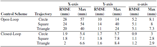
Error analysis of moving platform position correction system.

5.2. Results of MP Cartesian motion tracking for control robot system and camera-based Closed-Loop system
In this section, the motion of the MP is monitored using a 3D depth camera to evaluate motion errors tracked during open-loop control. These errors are then corrected, tracked, and compared using vision-based closed-loop control, all facilitated by Realsense camera. In order to optimize and rectify motion errors, an analysis is carried out comparing the theoretically calculated desired Cartesian trajectories for circular, square, and triangular motions with the trajectories executed in the plane tracked by the depth camera for both control schemes. The curves captured by the camera reveal errors due to various factors. To help analyze these errors, Table III presents the errors obtained for each trajectory. The evaluation metrics include RMSE and the maximum error to assess the reduction in error achieved by the closed-loop compared to open-loop control. These metrics provide insights into the accuracy and effectiveness of the closed-loop control system in minimizing motion errors. The values in Table III for X, Y, and α axes were measured by the experiment, as well as the error of the trajectory reference values.
Comparison of circular cartesian trajectory tracking in the X-Y plane: Open-loop robot control vs. camera-based closed-loop correction with circular trajectory steps executed by the moving platform of our cable-driven parallel robot.

Figure 9 illustrates a comparison between both open-loop and closed-loop results with the desired trajectory for the circular motion achieved for the two control schemes. The MP follows a circular path, and the depth camera tracks its positions, which is shown in the figure from the starting point to the final destination, passing through different points. Notably, the open-loop trajectory exhibits a curve that takes on a circular shape with a variable radius, offset from the center compared to the desired trajectory, and reveals high RMSE values. Based on the results presented in Table III, as the MP moves in a circular path, the RMSE values for the open-loop were 28 mm for the X-axis and 10 mm for Y-axis. These results are displayed in Figure 10, illustrating the MP displacement in the X and Y axes over time evolution for the closed-loop and open-loop control methods as well as their deviation from the desired trajectory. In contrast, the closed-loop trajectory showed RMSE values decrease to 1.9 mm and 1.7 mm for the X and Y axes, respectively. By the same measure, the maximum error across the entire range of planar parameters decreased significantly, from 57, 14 mm and 8.1° to 5.4, 5.7 mm and 3° for the X and Y axes, respectively.
Furthermore, as depicted in Figure 11, the orientation of the MP exhibits instability, manifesting left and right shifts, resulting in 5.2° RMSE for α and maximum error reaching 8.1°. This Cartesian behavior is attributed to the cable’s influence during the movement and corrected via the correction scheme to reduce the RMSE value to 0.9° and maximum error by 82% to 3°.
Circle cartesian trajectory variation for both closed-loop and open-loop robot control as a function of time (a) moving platform (MP) displacement in the X-axis, (b) MP displacement in the Y-axis, (c) MP displacement error in the X-axis, and (d) MP displacement error in the Y-axis.

Moving platform orientation variation as a function of time during circle trajectory for both closed-loop and open-loop robot control.

Introducing an error compensation scheme led to an 88% reduction in Y-axis error and an 88% decrease in X-axis error. Furthermore, there was a noticeable improvement in MP rotation, with error decreasing by 38.4%. The position curve oscillates relative to the reference curve, alternating between values above and below the reference position. This oscillation is attributed to the PD correction applied to the robot control.
The same analysis strategy for the square MP motion in Figure 12 is applied. We observe a comparison of the square motion trajectories achieved through two control schemes: open-loop and closed-loop, compared with the desired trajectory. The figure also depicts the tracking of the MP as it traverses a square path, capturing its positions at each of the four corners.
Comparison of square cartesian trajectory tracking in the X-Y plane: Open-loop robot control vs. camera-based closed-loop correction with steps executed by our cable-driven parallel robot, and the moving platform tracked at the four corners of the path.

Square cartesian trajectory variation for both closed-loop and open-loop robot control as a function of time (a) moving platform (MP) displacement in the X-axis, (b) MP displacement in the Y-axis, (c) MP displacement error in the X-axis, and (d) MP displacement error in the Y-axis.

The open-loop trajectory represents a square-shaped trajectory but shows a very significant deviation at the corners of the square as the MP is inclined and exhibits an RMSE of 23.1 mm.
The results indicate that during the motion of the MP in a square pattern, the RMSE values for the open-loop were 24 mm for X-axis, 14 mm for Y-axis, respectively, as shown in Figure 13 we can see the curves as function of time as well as the recorded error of the two systems in relation to the desired trajectory, and 5.1° for α, while in contrast, for the visual servoing the RMSE values of the trajectory were 1.8 mm for X, 1.8 mm for Y, and 1.1° for α, respectively.
Moving platform orientation variation as a function of time during square trajectory for both closed-loop and open-loop robot control.

Utilizing the error compensation scheme resulted in a 92% reduction in error on the X-axis, while there was a high increase of 87% for the Y-axis. Additionally, as shown in Figure 14, the error reduction is evident in the rotation of the MP, with a decrease of 78% in the RMSE value, from 5.1° to 1.1°.
Also, the effect of this correction system is even more obvious through the maximum error recorded for all these planar parameters, these values have significantly decreased the MP, from 54, 40 and 8° to 7.1, 7.8 mm and 2.8° for the X, Y, and α axes, respectively.
Similar results were obtained in planar triangular Cartesian trajectory as shown in Figure 15, which compares camera-based open-loop correction and closed-Loop CDPR control to the reference trajectory. The figure also illustrates the trajectory of the MP as it follows a triangular path, tracking its positions from the starting point to the final destination, passing through each of the three corners.
Comparison of triangle cartesian trajectory tracking in the X-Y plane: Open-loop robot control vs. camera-based closed-loop correction with steps executed by our cable-driven parallel robot, and the moving platform tracked at the three corners of the path.

Triangle cartesian trajectory variation for both closed-loop and open-loop robot control as a function of time (a) moving platform (MP) displacement in the X-axis, (b) MP displacement in the Y-axis, (c) MP displacement error in the X-axis, and (d) MP displacement error in the Y-axis.

Besides, Figures 16 and 17 present Cartesian Trajectory and the orientation Variation of the MP as a Function of Time as well as their errors to reference to the desired trajectories during triangle Trajectory. Despite the linear nature of motions in open-loop control, the behavior of the cables, as well as the imprecise starting position of the MP, introduces errors in the angle of each rectilinear motion direction, and significant deviations occur at the corners of the triangle. This results in RMSE values of 20, 11 mm and 5.1° at X, Y, and α axes, respectively. Thanks to closed-loop scheme, these errors are reduced to RMSE values of 2, 1.6 mm and 1.2° at X, Y, and α, respectively.
Moving platform orientation variation as a function of time during triangle trajectory for both closed-loop and open-loop robot control.

Similarly, the maximum error covering all planar parameters in the error curves shown in Figs. 16 and 17 has been significantly reduced, from 40, 24 mm and 7.3° to 6.6, 8.4 mm and 2.9° along the X, Y, and α axes, respectively.
The implementation of the visual servoing scheme produced a complete elimination of errors on the Y-axis, alongside a minor increase ranging between 0.2% and 2% on the X-axis. Furthermore, a noticeable decrease in error rates was observed in the rotation of the MP, with a reduction of 38.4% from the initial 32.5% to 20.5%. The curve also oscillates in these motions for closed-loop control and the shapes of the trajectories are closer to reality.
5.3. Discussion
In the results shown, the open-loop control strategy exhibits greater errors than the closed-loop control strategy, indicating that multiple factors contribute to these errors. Visual servoing minimizes these errors in our planar CDPR, demonstrating that the algorithm we implemented improves the accuracy.
Firstly, in the open-loop scheme performed by the CDPR, the errors occurred due to the starting position, making it difficult to follow the reference path. The initial position is one of the primary factors identified which can cause significant errors in the desired trajectories. There is a disparity between the desired and actual poses on both axes, with the Y-axis generally outperforming the X-axis. Errors on the horizontal X-axis are greater than those on the vertical Y-axis. The RMSE for the X-axis ranges from 20 to 30 mm, while for the Y-axis it is between 10 and 15 mm. This can be attributed to the starting position of the coordinate path, which is offset by 500 mm to the left of the center on the X-axis. In contrast, for the closed-loop system, the overall error is extremely close for both axes, with an RMSE of 1.8 mm for the X and Y axes for the square trajectory. Based on these results, we can conclude that initial position correction through visual servoing improves the accuracy of the trajectory.
Furthermore, in open-loop control, the orientation of the MP also deviates during the trajectory, reaching an RMSE of 5° and a maximum error exceeding 7°. For all trajectories, the orientation curve of the MP increases and then decreases. The α value varies with y, showing positive values when y > 0 and as the MP approaches the upper motors, and negative values when y < 0 and as the MP approaches the lower motors. The displacement of the MP along the X-axis shows larger deviations than those along the Y-axis. The error is lower for the triangular trajectory because the MP remains farther from the corners, in comparison with other motions, resulting in less orientation deviation. In the square trajectory, the α error is higher due to the proximity of the corners to the motors, leading to significant orientation deviations. The relationship between the Cartesian position of the MP and the cable lengths is evident, so the orientation of the MP changes based on its position along the trajectory and is influenced by the forces exerted by the cables. When the MP approaches a particular motor, the corresponding cable shortens and becomes tighter, exhibiting less elasticity, greater rigidity, and higher tension. Conversely, longer cables show more elasticity and flexibility, resulting in lower rigidity and tension. These cables exert less influence on the orientation of the MP. When the MP is closer to the upper motors, it rotates in the direct direction; when it is closer to the lower motors, it rotates in the reverse direction. Thus, the tighter cables have higher tension and exert greater forces on the MP, directing its movement toward the motor.
The closed-loop system controls the orientation of the MP in the opposite direction to its rotation in order to rectify it, which explains the MP’s stability. As a result, the recorded RMSE is around 1°, with a reduction of over 75% and a maximum orientation of 3° for all trajectories. Contrary to the assumptions of the CPPR model, the cables are not rigid, but rather flexible and elastic. This flexibility, which is not taken into account in our model, leads to additional errors in the system’s performance.
Overall, the cable’s behavior creates uncertainties and perturbations in the MP’s motion, as well as the initial position error for open-loop control, which can directly impact the accuracy of the trajectory performed. The visual servoing control strategy is implemented to ameliorate these results, and a real-time PD correction algorithm improves system performance. The closed-loop system, based on feedback from the depth camera, maintains correction of the calculated IK with respect to the trajectory followed by the camera. The error compensation obtained is high, exceeding 85% for all generated trajectories: triangle, square, and circle, and reaching up to 95%. The error values recorded by the correction scheme showed interesting results. RMSE remains below 2 mm and the maximum error is less than 8 mm. Closed-loop control system also improves MP orientation, which has become more stable with an orientation RMSE of less than 1.2°. This is considered a suitable accuracy for functional rehabilitation applications. This improvement in control accuracy is due to the correction of the starting position and the reduction in trajectory error. This correction implicitly affects the cable’s behavior.
6. Conclusion
A closed-loop visual control system for a planar cable robot has been addressed and investigated. The previous control scheme, which relied on encoder feedback, has been refined by incorporating closed-loop visual control through depth/RGB camera tracking in the Cartesian space, alongside error compensation and PD correction. Control of the robot’s MP via the actuators’ encoders proved insufficient due to cable behavior and initial position estimation, resulting in high errors in the open-loop control of Cartesian motion. Specifically, the RMSE exceeded 20 mm on the X-axis and 10 mm on the Y-axis, with the maximum orientation of the MP exceeding 20°, thereby reducing system accuracy. The integration of visual feedback into the control strategy aimed to obtain the absolute and true Cartesian position of the MP. Both control schemes were evaluated on three trajectories: circular, square, and triangular. Overall, the open-loop control scheme exhibited reduced performance, with errors reaching an RMSE of 30 mm during runtime. In contrast, the error correction with closed-loop visual control demonstrated superior performance, substantially reducing errors for all trajectories. The RMSE value was significantly lower, measuring less than 2 mm. Error reduction percentages were 92%, 88%, and 85% for circular, square, and triangular trajectories, respectively.
Abbreviations
- MP:
Moving Platform
- EE:
End-Effector
- PD:
Proportional-Derivative
- CDPR:
Cable-driven Parallel Robot
- IK:
Inverse Kinematic
- PLC:
Programmable Logic Controller
- DOF:
Degrees of freedom
- DKM:
Direct Kinematic Model
- RMSE:
Root Mean Square Error
- R2:
R-squared
Author contributions
Kaiss Ghrairi developed the trajectory correction, control, and command algorithms for the robot, implemented the applications, and wrote the article. Houssein Lamine contributed to supervision, technical correction, and verification of the robot’s algorithms and control, as well as the analysis of the results. Sami Bennour and Abdelbadiâ CHAKER conceived and led the robot development project, secured funding, and contributed to the revision of the article. All authors have read and approved the final version of the manuscript.
Financial support
This work was supported by the Programme d’Encouragement des Jeunes Chercheurs under grant number 18PJEC12-07: "Development of a robotic platform for the diagnosis and functional rehabilitation of lower limbs."
Competing interests
The authors declare no conflicts of interest.
Ethical approval
Not applicable.