1. Introduction
In recent years, various underwater engineering structures, such as bridges, offshore oil and gas platforms, and port docks, have experienced rapid development and widespread application. During their prolonged service life, these facilities are susceptible to issues such as component loosening and corrosion, necessitating regular inspection and maintenance [Reference Yang, Liu, Su, Zhang, Xia and Chen36]. However, the high-pressure and low-temperature conditions of underwater environments constrain the operational time and range of divers. Consequently, underwater robotic technology has garnered extensive attention and application as a substitute for manual operations, with the aim of reducing operational costs and risks while enhancing efficiency [Reference Sivčev, Coleman, Omerdić, Dooly and Toal30].
Autonomous obstacle avoidance is a fundamental capability for autonomous operation of underwater robots. Robots equipped with autonomous obstacle avoidance can perceive their surrounding environment in real time, intelligently plan their trajectories, and avoid collisions and damage, thereby extending the lifespan of equipment and reducing maintenance costs. Underwater engineering maintenance robots [Reference Chen, Liu, Zhang, Zheng and Yang2, Reference Fan, Yang, Chen, Wang, Huang, Shou, Jiang and Wei6, Reference Hong, Chung, Kim, Kim, Kim and Yoon15] are required to transition between multiple operational points within structurally complex underwater infrastructures. The ability to autonomously avoid obstacles enhances the efficiency and precision of task execution, particularly by increasing the robots’ autonomy in extreme or hazardous environments, reducing reliance on human intervention, and improving overall operational safety.
An ideal autonomous obstacle avoidance method must operate reliably in unknown and dynamic environments and adapt to various structural types of operational settings, as demonstrated in recent studies on path-finding controllers for marine vehicles using neural network techniques and intelligent hybrid stochastic methods [Reference Hussein and Al-Araji18, Reference Hussein and Al-Araji19]. Existing optimal obstacle avoidance strategies typically depend on predefined path planning algorithms and sensor feedback, such as LiDAR, sonar, and depth sensors, to perceive the surrounding environment and make real-time adjustments through obstacle avoidance algorithms [Reference Yu, Qiao and Shen39]. Reinforcement learning (RL)-based autonomous obstacle avoidance approaches construct agent models that enable robots to autonomously learn optimal avoidance strategies through continuous environmental interactions, thereby offering a novel solution to real-time obstacle avoidance challenges faced by engineering maintenance robots in unknown environments with nonlinear and high-dimensional perceptual inputs. Mnih et al. [Reference Mnih, Kavukcuoglu, Silver, Rusu, Veness, Bellemare, Graves, Riedmiller, Fidjeland, Ostrovski, Petersen, Beattie, Sadik, Antonoglou, King, Kumaran, Wierstra, Legg and Hassabis27] were the first to integrate deep learning into the RL domain, establishing an end-to-end training framework with strong generalizability. Currently, research on robot motion based on deep reinforcement learning (DRL) has been widely applied to terrestrial robots with positive results [Reference Kashyap, Parhi and Kumar20, Reference Yadav, Nagar and Shah35, Reference Yu, Fu, Tian, Yang and Yang38, Reference Zhang, Ju and Cao40], and relevant studies have also emerged in the field of underwater mobile robotics [Reference Chen, Tu, Zhang, Zhou and Yang3, Reference Zhang, Miao, Li, Jia, Wei, Gong and Wen41]. Chu et al. [Reference Chu, Wang, Lei and Luo4] applied DRL to enhance the anti-interference capabilities of autonomous underwater vehicles (AUVs) in ocean currents, achieving effective path planning through the implementation of dynamic reward functions. Hadi et al. [Reference Hadi, Khosravi and Sarhadi12] utilized DRL for target tracking and adaptive motion planning in AUVs, guiding simulated AUVs to accurately navigate toward targets. Additionally, the efficacy of DRL in obstacle avoidance for underwater robots has been demonstrated. He et al. [Reference He, Dong, Sun and Wang13] employed a DRL -based path planning algorithm that transformed online computational processes into offline training processes, enabling robots to learn autonomous planning, tracking, and emergency obstacle avoidance. Sun et al. [Reference Sun, Ran, Zhang, Xu and Wang31] developed an end-to-end DRL method that maps sensor inputs to control commands, facilitating collaborative guidance and swarm dynamic obstacle avoidance in unknown environments. Liu et al. [Reference Liu, Huang and Zhao23] proposes an AUV obstacle avoidance control algorithm using offline RL, specifically conservative Q-learning based on the soft actor-critic framework, demonstrating effective navigation in complex marine environments. Wu et al. [Reference Wu, Song, Hsu, You and Wu34] designed an end-to-end learning architecture based on DRL algorithms, allowing AUVs to perform sonar-based obstacle avoidance and visual sensor pipeline tracking tasks in unknown simulated environments. These research results confirm the feasibility of DRL methods; however, they are predominantly established within simulated environments. Given the complex hydrodynamic models inherent to underwater robots, the discrepancies between simulation validation and real-world applications persist. The ultimate objective of simulation research is to facilitate its application in the control of real-world robotic systems.
The application of DRL algorithms in real-world robot obstacle avoidance is limited primarily due to the uncontrollable nature of the training process. In the early stages of training the avoidance strategy, the robot inevitably experiences numerous collisions, which are costly and slow the training progress. A potential feasible solution is to train the robot’s strategy in a simulation environment and transfer the matured strategy to the real robot for deployment [Reference Ma, Wang, Tang, Wang and Wang25]. However, the deployment of the transferred strategy requires high consistency between the virtual and real robots, including perceptual inputs, system models, and output responses, which is particularly important for nonlinear, strongly coupled underwater robot systems. Therefore, it is necessary to establish a high-fidelity simulation system. Such a simulation system can test the vehicle’s code before high-risk deployment. Although real-world validation is still required, it can greatly reduce failure risks and debugging time during the verification process [Reference Player, Chakravarty, Zhang, Raanan, Kieft, Zhang and Hobson28]. In this context, the modeling process plays a crucial role in accurately replicating the physical entities [Reference Tao, Xiao, Qi, Cheng and Ji32]. Currently, most research on underwater simulation models focuses on the design and development stages. For example, Hu et al. [Reference Hu, Liang, Huang and Yang17] constructed a simulation model of underwater vehicles, describing the modeling process from geometric, physical, environmental, and behavioral aspects. Kutzke et al. [Reference Kutzke, Carter and Hartman21] framed the design process of unmanned underwater vehicles (UUVs) as a multi-objective optimization problem, improving system and subsystem reliability through simulation-based development. The use of high-fidelity simulation systems to facilitate the transfer of control strategies to real robots holds significant research value. X. Yang et al. [Reference Yang, Gao, Wang, Long and Fu37] combined simulation systems with RL to achieve real-time underwater grasping capabilities for robotic arms. Liu et al. [Reference Liu, Xu, Liu and Wang24] proposed a digital twin approach for industrial assembly scenarios, enabling the effective transfer of DRL-trained strategies to physical robots. However, due to the nonlinear, strongly coupled, and multi-interference characteristics of underwater systems, training obstacle avoidance strategies for underwater robots in simulation and transferring them to real robot applications remains a challenge.
In summary, traditional obstacle avoidance strategies designed for specific scenarios struggle to meet the increasingly diverse application requirements of underwater robots. DRL algorithms offer a viable solution for developing generalized avoidance strategies; however, these robust policies require extensive training that would be prohibitively costly in real environments. Regarding existing simulation-based training approaches, two significant challenges remain: first, current simulation training strategies face deployment difficulties on real robots due to the sim-to-real gap; second, existing simulation environments typically lack hydrodynamic configurations, making them unsuitable and inefficient for underwater robot training.
Overall structure of the underwater robot.

Autonomous exploration and obstacle avoidance for underwater robots have become a future development trend. As various novel underwater robots are developed, their autonomous obstacle avoidance strategies and parameters need to be validated through numerous high-cost, repetitive experiments. High-fidelity simulation models can train obstacle avoidance strategies in a virtual environment and facilitate their transfer to real-world applications. Based on these needs, this paper investigates the Sim-to-Real pipeline for RL-based autonomous obstacle avoidance in underwater robots. The main contributions of this paper are as follows:
-
1. This paper analyzes the kinematic and dynamic models of underwater robots and constructs a simulation system, optimizing the potential gap between simulation and reality through comprehensive input, modeling, and output processes, effectively replicating the robot’s motion and control responses in real underwater conditions.
-
2. The paper trains and validates an obstacle avoidance strategy based on a high-fidelity simulation system, proposing a DRL-based obstacle avoidance strategy that ensures safe autonomous exploration in operational environments.
-
3. The proposed obstacle avoidance strategy is transferred to a real underwater robot system, where pool-based obstacle avoidance experiments were conducted. The robot successfully explored the environment and autonomously avoided obstacles in three underwater environments, demonstrating the effectiveness of the Sim-to-Real pipeline for RL-based autonomous obstacle avoidance in underwater robots.
2. Underwater robot modeling
2.1. System overview
The underwater robot used in this study is a typical open-frame ROV structure, as shown in Figure 1. The high openness of the structure allows for the accommodation of additional equipment, with all electronic components centralized within a cylindrical hull. This hull serves as the core of the system, providing stability to the robot in multiple degrees of freedom during underwater operation. The design parameters of the underwater robot are listed in Table I.
Physical parameters of the UMR.

To achieve autonomous obstacle avoidance functionality, the robot is equipped with stereo cameras and an inertial measurement unit (IMU) as its primary sensors. The stereo cameras use the principle of disparity to determine the distance to obstacles in the robot’s path. The cameras have a maximum horizontal field of view of
 $90^{\circ}$
and a vertical field of view of
 $60^{\circ}$
. The maximum frame rate can reach 100 FPS, with a CMOS sensor having approximately 12.3 million effective pixels, offering high resolution and a wide dynamic range. Let
 $f$
represent the focal length of the camera, and
 $T$
denote the baseline, which is the distance between the optical centers of the left and right cameras. A spatial point
 $P$
produces images at positions
 $x^{l}$
and
 $x^{r}$
on the left and right camera image planes, respectively, with the disparity
 $d=x^{l}-x^{r}$
which corresponds to the distance between the two points on the image plane. The distance
 $Z$
of the spatial point
 $P$
relative to the stereo camera can be calculated as [Reference Trucco and Verri33]:
 \begin{equation} Z=\frac {fT}{x^{l}-x^{r}}=\frac {fT}{d} \end{equation}
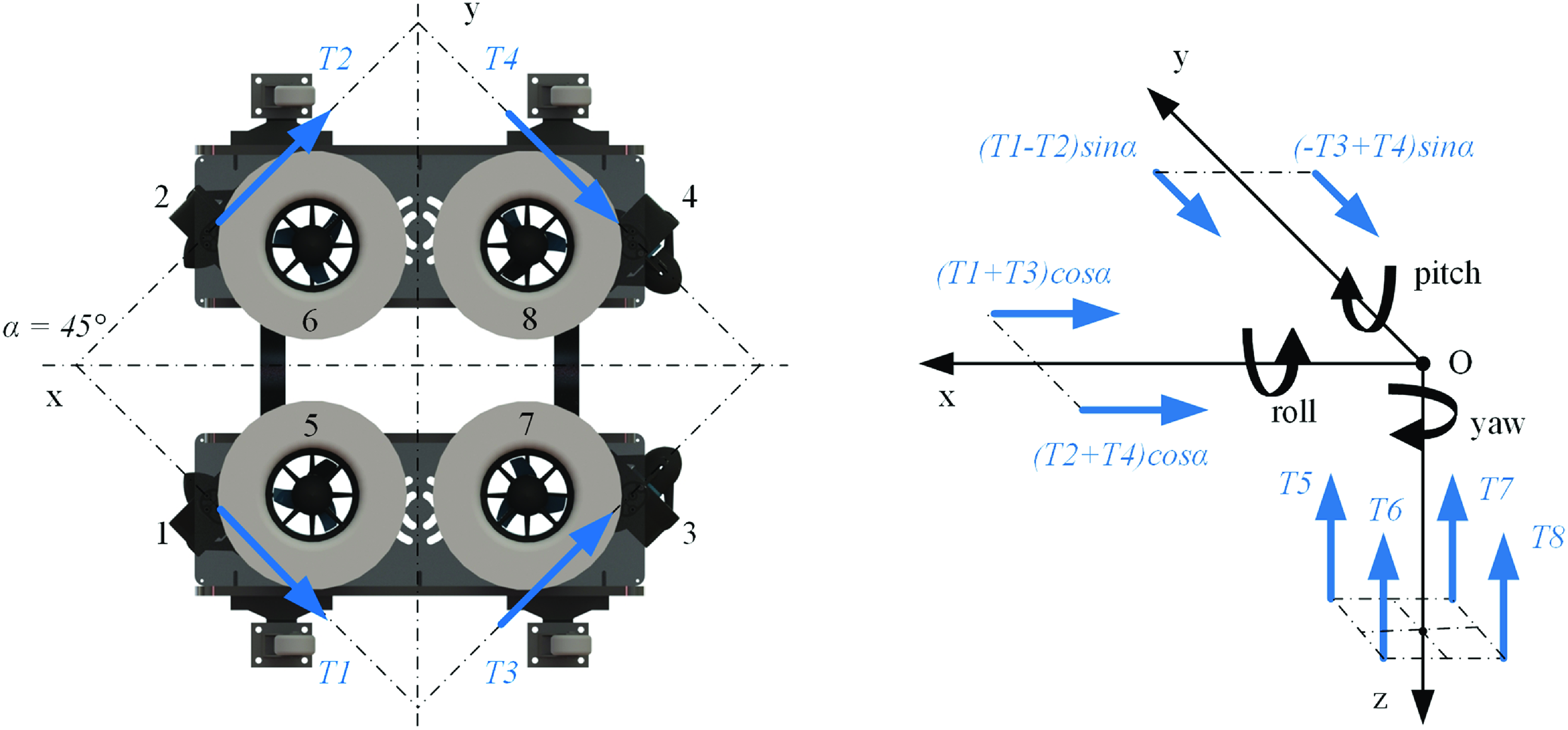
In order to enhance the robot’s maneuverability, an 8-thruster layout is designed, as shown in Figure 2. Here,
 $T_{i}$
(
 $i=1,2\ldots ,8$
) represents the forces and directions of the horizontal thrusters when the robot moves forward. Four horizontal thrusters are arranged along the horizontal axis at an angle
 $\alpha =45^{\circ}$
to meet both steering and translation requirements, while four vertical thrusters ensure the robot’s depth control.
Underwater robot propeller arrangement and thrust distribution diagram.

2.2. Kinematic modeling
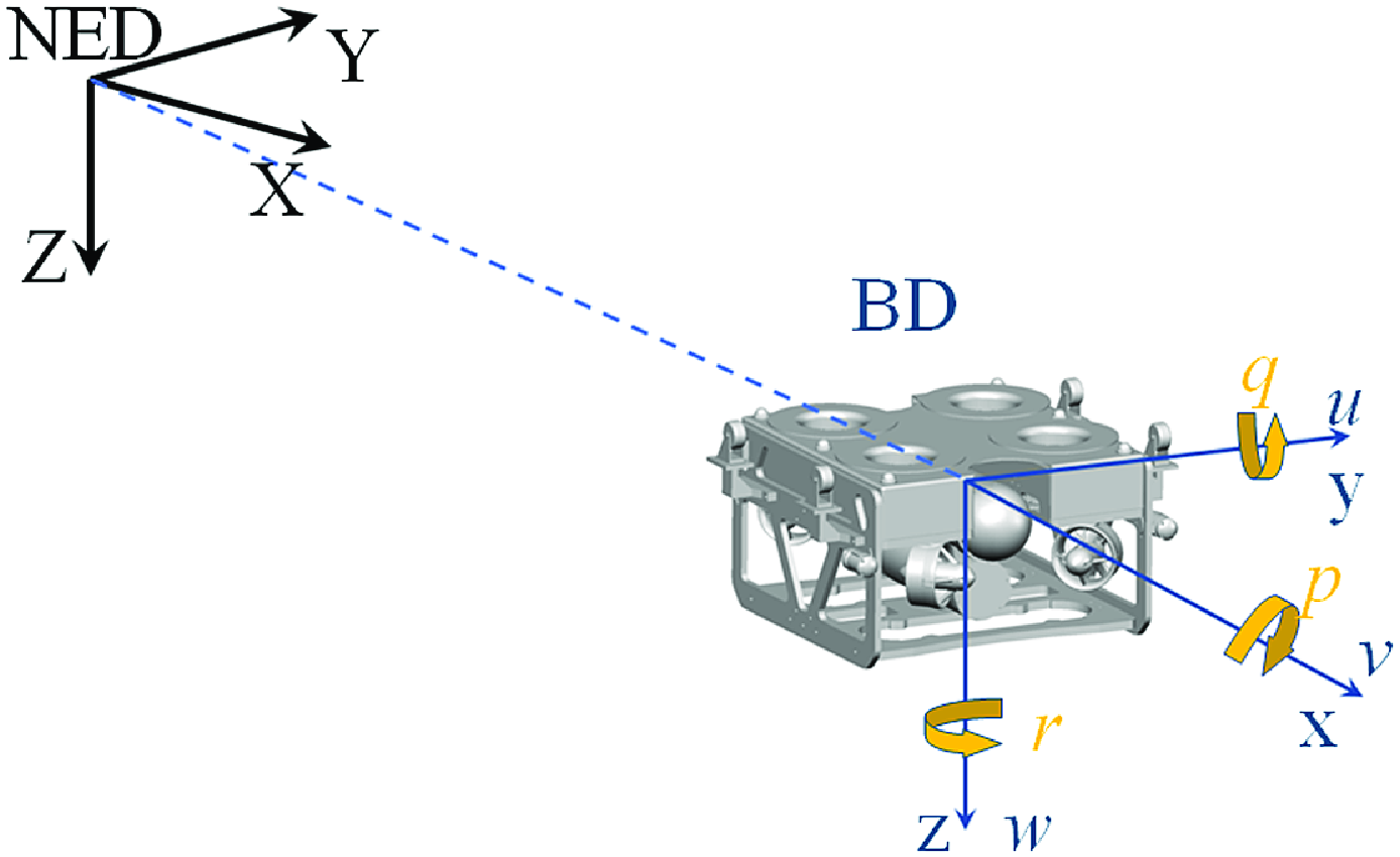
To accurately replicate the motion behavior of the underwater robot in the simulation environment, this paper analyzes the motion model of the underwater robot, providing a theoretical foundation for the subsequent establishment and optimization of the simulation environment. As shown in Figure 3, the North East Down (NED) coordinate system is established as the fixed spatial reference frame, and the Body Down (BD) coordinate system is established as the robot’s moving reference frame relative to the fixed coordinate system. These two coordinate systems form the basis for establishing the kinematic model.
Robot motion coordinate system.

Let
 $x$
,
 $y$
,
 $z$
represent the robot’s BD distances relative to NED, and
 $\phi$
,
 $\theta$
,
 $\psi$
represent the BD rotation angles relative to NED. The robot’s position and orientation in NED can thus be expressed as follows [Reference Fossen7]:
 \begin{equation} \eta = \begin{bmatrix} \eta _1 \\ \eta _2 \end{bmatrix} = \begin{bmatrix} x & y & z & \phi & \theta & \psi \end{bmatrix}^T \end{equation}
The UMR uses four horizontal thrusters to achieve translation along
 $x$
,
 $y$
, and yaw. Four vertical thrusters work together to achieve translation along
 $z$
, roll, and pitch. The robot’s velocity in BD is expressed as follows:
 \begin{equation} v = \begin{bmatrix} v_1 \\ v_2 \end{bmatrix} = \begin{bmatrix} u & v & w & p & q & r \end{bmatrix}^T \end{equation}
where
 $v_1$
represents linear velocity, with the transformation matrix between NED and BD given by
 \begin{equation} J_1(\eta _2) = \begin{bmatrix} \cos \theta \cos \psi &\quad \sin \phi \sin \theta \cos \psi - \cos \phi \sin \psi &\quad \cos \phi \sin \theta \cos \psi + \sin \phi \sin \psi \\ \cos \theta \sin \psi &\quad \sin \phi \sin \theta \sin \psi + \cos \phi \sin \psi &\quad \cos \phi \sin \theta \sin \psi - \sin \phi \cos \psi \\ -\sin \theta &\quad \sin \phi \cos \theta &\quad \cos \phi \cos \theta \end{bmatrix} \end{equation}
and
 $v_2$
represents angular velocity, with the transformation matrix between NED and BD given by
 \begin{equation} J_2(\eta _2) = \begin{bmatrix} 1 &\quad \sin \phi \tan \theta &\quad \cos \phi \tan \theta \\ 0 &\quad \cos \phi &\quad -\sin \phi \\ 0 &\quad \sin \phi /\cos \theta &\quad \cos \phi /\cos \theta \end{bmatrix} \end{equation}
The robot’s kinematic equation is ultimately expressed as follows:
 \begin{equation} \begin{bmatrix} \dot {\eta }_1 \\ \dot {\eta }_2 \end{bmatrix} = \begin{bmatrix} J_1(\eta _2) &\quad O_{3\times 3} \\ O_{3\times 3} &\quad J_2(\eta _2) \end{bmatrix} \begin{bmatrix} v_1 \\ v_2 \end{bmatrix} \end{equation}
2.3. Dynamic modeling
The robot is considered an ideal rigid body, and its underwater dynamics, taking damping into account, can be modeled as follows [Reference Fossen and Sagatun8]:
 \begin{equation} M\dot {v} + C(v)v + D(v)v + g(\eta ) = \tau \end{equation}
where
 $M$
is the inertia matrix,
 $C(v)$
is the Coriolis and centripetal force matrix,
 $D(v)$
is the damping matrix due to the fluid viscosity and surface drag,
 $g(\eta )$
is the restoring force matrix due to gravity and buoyancy, and
 $\tau$
is the thrust matrix generated by multiple thrusters. The inertia matrix
 $M$
consists of the rigid-body inertia matrix
 $M_R$
and the added mass inertia matrix
 $M_A$
. Let the robot’s center of gravity in the BD frame be
 $r_g = \begin{bmatrix} x_g & y_g & z_g \end{bmatrix}^T$
and the center of buoyancy be
 $r_b = \begin{bmatrix} x_b & y_b & z_b \end{bmatrix}^T$
. The moment of inertia matrix is
 $I_0$
. The rigid-body inertia matrix
 $M_R$
can be expressed as
 \begin{equation} M_R = \begin{bmatrix} mI_{3\times 3} &\quad -mS(r_g) \\ mS(r_g) &\quad I_0 \end{bmatrix} = \begin{bmatrix} m &\quad 0 &\quad 0 &\quad 0 &\quad mz_g &\quad -my_g \\ 0 &\quad m &\quad 0 &\quad -mz_g &\quad 0 &\quad mx_g \\ 0 &\quad 0 &\quad m &\quad my_G &\quad -mx_G &\quad 0 \\ 0 &\quad -mz_g &\quad my_g &\quad I_{xx} &\quad -I_{xy} &\quad -I_{xz} \\ mz_g &\quad 0 &\quad -mx_g &\quad -I_{xy} &\quad I_{yy} &\quad -I_{yz} \\ -my_g &\quad mx_g &\quad 0 &\quad -I_{xz} &\quad -I_{yz} &\quad I_{zz} \end{bmatrix} \end{equation}
Considering the symmetrical structure of the robot, the added mass matrix can be reasonably simplified, focusing only on the diagonal elements’ influence. The added mass inertia matrix
 $M_a$
can be represented as
 \begin{equation} M_a = \begin{bmatrix} X_{\dot {u}} & Y_{\dot {v}} & Z_{\dot {w}} & K_{\dot {p}} & M_{\dot {q}} & N_{\dot {r}} \end{bmatrix} \end{equation}
The Coriolis and centripetal force matrix
 $C(v)$
consists of the rigid-body Coriolis and centripetal force matrix
 $C_R(v)$
and the added mass Coriolis and centripetal force matrix
 $C_A(v)$
. Viscous damping
 $D(v)$
arises from the medium’s flow caused by the robot’s motion. Underwater damping forces mainly include quadratic and linear damping. At low speeds, the primary consideration is the diagonal elements’ effect. The viscous damping matrix can be expressed as
 \begin{equation} \begin{split} D(v) = -\text{diag}\{ & X_u + X_{u|u|}|u|, Y_v + Y_{v|v|}|v|, Z_w + Z_{w|w|}|w|, \\[6pt] & K_p + K_{p|p|}|p|, M_q + M_{q|q|}|q|, N_r + N_{r|r|}|r|\} \end{split} \end{equation}
The restoring force
 $g(\eta )$
allows the robot to maintain an initial attitude in water and return to this attitude once external forces are removed. Gravity
 $W=mg$
and buoyancy
 $B=\rho gV$
. The restoring force matrix is expressed as
 \begin{equation} g(\eta ) = \begin{bmatrix} (W-B)\sin \theta \\[2pt] -(W-B)\cos \theta \sin \phi \\[2pt] -(W-B)\cos \theta \cos \phi \\[2pt] -(y_gW-y_bB)\cos \theta \cos \phi +(z_gW-z_bB)\cos \theta \sin \phi \\[2pt] (z_gW-z_bB)\sin \theta +(x_gW-x_bB)\cos \theta \cos \phi \\[2pt] -(x_gW-x_bB)\cos \theta \sin \phi -(y_gW-y_bB)\sin \theta \end{bmatrix} \end{equation}
The thrust matrix
 $\tau$
is related to the arrangement of the thrusters. The positions of the eight thrusters on the robot are shown in Figure 2. Assume the robot’s center of gravity coincides with its geometric center, and each thruster produces a thrust
 $T_{i}$
(
 $i=1,2\ldots ,8$
). The distances from the thrusters to the robot’s center of gravity are
 $c_1$
,
 $c_2$
, and
 $c_3$
. The thruster thrust matrix can be represented as
 \begin{equation} \tau = \begin{bmatrix} F \\[2pt] M \end{bmatrix} = \begin{bmatrix} (T_1+T_2+T_3+T_4)\cos \alpha \\[2pt] (T_1-T_2-T_3+T_4)\sin \alpha \\[2pt] T_5+T_6+T_7+T_8 \\[2pt] c_1(-T_5+T_6-T_7+T_8) \\[2pt] c_2(-T_5-T_6+T_7+T_8) \\[2pt] c_3(T_1-T_2+T_3-T_4)\sin \alpha \end{bmatrix} \end{equation}
3. Simulation training system construction and optimization
The underwater robot needs to make autonomous obstacle avoidance decisions in operational scenarios without prior maps. DRL based on trial-and-error training is effective in developing autonomous strategies. However, training in real-world environments inevitably leads to numerous collisions and high costs. Therefore, the Sim2Real approach, where the strategy is trained in a simulation environment and then deployed in real-world scenarios, presents a more optimal solution. To directly apply the model trained in the simulation system to the obstacle avoidance control of the real robot, it is essential to minimize the gap between the simulation system and the real system. This paper constructs a simulation system for the autonomous obstacle avoidance training of underwater robots, analyzes the sources of error, and adopts error optimization measures, ultimately forming an effective simulation training system.
3.1. Simulation system
Compared to widely used terrestrial simulation platforms, there is currently no established RL platform specifically for underwater robots. Popular simulators for terrestrial robots, such as MuJoCo and Isaac Gym, do not support fluid dynamics settings, which are critical for accurately describing the motion of underwater robots, making them unsuitable for underwater applications. The Gazebo-based UUVSimulator [Reference Manhães, Scherer, Voss, Douat and Rauschenbach26] underwater simulation plugin offers a relatively complete underwater simulation framework, including typical underwater sensors, thrusters, and hydrodynamic models. However, it is mainly used for validating motion control algorithms of underwater vehicles and lacks RL training capabilities. This paper builds upon the UUVSimulator as the foundational environment to develop a simulation training system for the autonomous obstacle avoidance of underwater robots, as shown in Figure 4.
Sim-to-real pipeline for training underwater robot autonomous obstacle avoidance based on high-fidelity models.

The system architecture implements modular encapsulation of various functional components, including the robot agent, simulation environment, and policy iteration components. The robot agent is accurately modeled based on the kinematic and dynamic equations derived in Section 3 , replicating the actual force conditions during the robot’s movement. The simulation environment includes obstacle configurations, fluid dynamics, and other settings. Among these, ocean currents are a significant influencing factor. The ocean current can be modeled using a first-order Gaussian-Markov process, as shown below, which represents the typical characteristics of ocean currents [Reference Fossen7]:
 \begin{equation} \dot {v}_c + \mu v_c = w \end{equation}
where
 $v_c$
represents the water current velocity,
 $w$
represents Gaussian white noise, and
 $\mu$
is a constant coefficient (
 $\mu \gt 0$
).
To enable the application of RL algorithms in the underwater robot system simulation platform, this paper utilizes OpenAI Gym [Reference Brockman, Cheung, Pettersson, Schneider, Schulman, Tang and Zaremba.1] as the policy training interface. OpenAI Gym is a widely used tool for training and evaluating RL algorithms. The interface’s step function represents a control time step in the simulation. Through this command, the simulation environment accepts the action provided by the algorithm’s policy and returns the outcome of that action in the simulation. The reset function is a utility function that resets the environment to its initial state using the internal domain initialization plugin of the simulation platform. It returns the initial state of the environment along with auxiliary diagnostic information. The render function is a request function for the visualization interface, which can return visual information about the environment, such as plan views, depth maps, point clouds, and other related data.
3.2. Error analysis and optimization
3.2.1. Robot system modeling
To improve the realism of the simulation platform, the underwater robot system simulation platform developed in this paper conducts detailed analysis in system kinematics and dynamics modeling, rather than using simple geometric shapes such as cuboids for model approximation. Additionally, when performing force and torque calculations with the underlying simulation engine, a fluid dynamics compensation plugin is incorporated based on hydrodynamic analysis. This allows the simulation engine to more accurately replicate the dynamic performance of the underwater robot system. Unlike terrestrial robots, a key aspect of accurately replicating the motion of underwater robots in the simulation system is the precise setting of hydrodynamics.
In the derived dynamic model, the hydrodynamic coefficient matrix is contributed solely by the diagonal elements, so only the hydrodynamic coefficients for axial translational motion and rotational motion around the axis need to be solved. Let
 $L$
denote the robot’s length. For translational motion along the axis, taking the x-axis as an example, the simulation flow field is established as shown in Figure 5. The entire fluid domain is defined with two sides along the x-axis as the fluid inlet and outlet, respectively, while all other outer surfaces are set as symmetry boundaries to extend the fluid domain range. Since the flow field for translational motion is relatively simple, the internal domain is divided into three sub-fluid domains. The interfaces between these subdomains are automatically generated as interface-type boundaries, with dimensions as shown in the Figure 5. During mesh generation, the internal robot wall surface is discretized into a surface mesh with a size of 2%
 $L$
, fluid2 is meshed with unstructured grids at 10%
 $L$
, and fluid1 and fluid3 are structured meshed at 15%
 $L$
.
(a) Computational domain of translational motion; (b) computational domain of rotational motion.

Based on the viscous hydrodynamic formulas, solving the damping force equations allows for the determination of the quadratic damping coefficient and the linear damping coefficient. The simulation conditions are set as follows:
-
• Calculation Model: The turbulence model used is SST k-omega.
-
• Material Configuration: The fluid domain is modeled with water at
 $20^{\circ}$
C (liquid state) with a density of
$998.2\, {\textrm {kg/m}}^{3}$
.
-
• Translational Motion: The velocity inlet is set to a steady flow ranging from −1 to 1 m/s, with tests conducted at intervals of 0.2 m/s. The pressure outlet is set to a gauge pressure of 0.
-
• Rotational Motion: The fluid_robot region is configured as frame motion, with the rotation axis along the z-axis. The rotational speed is set to range from −3 to 3 rad/s, with tests conducted at intervals of 0.5 rad/s.
-
• Solution Method: The pressure–velocity coupling algorithm used is the SIMPLE method, and the discretization scheme for turbulent kinetic energy and specific dissipation rate is set to second order upwind.


Visualization: The surface pressure (a) and the velocity distribution (b) when UDOR moving at the velocity of 0.2 m/s; the surface pressure (c) and the velocity distribution (d) when robot yawing at the angular velocity of 0.5 rad/s.

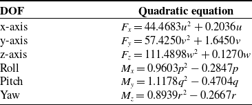
The simulation results are shown in Figure 6. It can be observed that during the robot’s rotation around each axis underwater, the inertial hydrodynamic resistance torque is quadratic with respect to the rotational speed, which aligns with the expected derivation. By averaging the resistance and torque data obtained under both forward and reverse flow conditions and fitting the results (Figure 7), the quadratic curve representation of the viscous hydrodynamic resistance and torque can be derived, as shown in Table II.
Quadratic equations of damping at each DOF.

(a) Curves of quadratic damping for translational motion at different velocities; (b) curves of quadratic damping for rotational motion at different angular velocities.

For calculating the added mass of a complex-shaped body, the resistance
 $F$
and torque
 $M$
results from the steady-state flow simulation are used. Accelerations
 $a$
and angular accelerations
 $\alpha$
are applied at the current flow speed, simulating the robot’s uniformly accelerated motion. The corresponding resistance
 $F_a$
and torque
 $M_\alpha$
are then calculated, from which the added mass
 $m_a$
and added rotational inertia
 $I_\alpha$
can be derived:
 \begin{equation} \begin{cases} m_a = \displaystyle\frac {|F_a - F|}{a} \\[12pt] I_\alpha = \displaystyle\frac {|M_\alpha - M|}{\alpha } \end{cases} \end{equation}
For translational motion along the x, y, and z axes, based on the results of the original 1 m/s steady-state flow simulation, a user defined function (UDF) is written in Fluent, using the DEFINE_PROFILE predefined macro to specify fluid acceleration. The acceleration is gradually increased from 0 to
 $1\, {\textrm {m/s}}^{2}$
at intervals of
 $0.2\, {\textrm {m/s}}^{2}$
. The simulation process is changed from steady-state to transient. For rotational motion around the x, y, and z axes, angular acceleration is specified to increase from 0 to
 $1\, {\textrm {rad/s}}^{2}$
at intervals of
 $0.2\, {\textrm {rad/s}}^{2}$
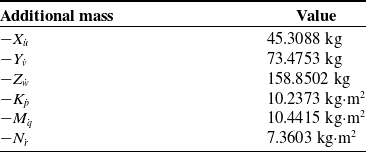
, based on the original 1 rad/s simulation results. After obtaining the simulation results, the robot’s added mass in each direction can be derived, as shown in Table III. The derived hydrodynamic coefficients are then loaded into the simulation system, enabling high-fidelity motion replication of the underwater robot.
Hydrodynamic added mass at each DOF.

3.2.2. State acquisition
The input perception for autonomous obstacle avoidance in underwater robots is primarily based on depth images obtained from stereo cameras, which are used to determine the distance and orientation of obstacles ahead. However, due to manufacturing errors in the shape of the camera lenses and errors in the mounting of the lenses and imaging positions, lens distortion often occurs during camera imaging. This type of deformation can cause lines in the image to become distorted, bent, or twisted, leading to discrepancies in state acquisition between reality and simulation. Lens distortion can be divided into radial and tangential distortions. Radial distortion, caused by the shape characteristics of the lens, typically results in a clear central image with distorted peripheral images.
Radial position of a point on the imaging device can be adjusted according to the following equation based on the first few terms of the Taylor series expansion around the optical center distortion [Reference Duane5, Reference Fryer and Brown9]:
 \begin{equation} \begin{cases} x_{\text{corrected}} = x\cdot \left(1 + k_1r^{2} + k_2r^4 + k_3r^6 \right) \\[3pt] y_{\text{corrected}} = y\cdot \left(1 + k_1r^{2} + k_2r^4 + k_3r^6 \right) \end{cases} \end{equation}
For tangential distortion, which occurs when the lens is not parallel to the imaging plane due to manufacturing errors, it can be represented by two additional parameters,
 $p_1$
and
 $p_2$
, yielding:
 \begin{equation} \begin{cases} x_{\text{corrected}} = x + \left[2p_1xy + p_2(r^{2} + 2x^{2})\right] \\[3pt] y_{\text{corrected}} = y + \left[p_1(r^{2} + 2y^{2}) + 2p_2xy \right] \end{cases} \end{equation}
In these equations,
 $(x,y)$
is the original position of the distorted point on the imaging device, while
 $(x_{\text{corrected}},y_{\text{corrected}})$
is the corrected new position.
 $k_1$
,
 $k_2$
,
 $k_3$
are the radial distortion coefficients, and
 $p_1$
,
 $p_2$
are the tangential distortion coefficients. In the pinhole model, the coordinates of a three-dimensional space point
 $[x_c \; y_c \; z_c]^T$
projected onto the normalized image plane
 $[x_p \; y_p]^T$
are
 \begin{equation} \begin{cases} x_p = x_c/z_c \\[3pt] y_p = y_c/z_c \end{cases} \end{equation}
Let the distorted position of this point in the original image be
 $[x_d \; y_d]^T$
, the distortion is obtained by adding the radial and tangential distortions:
 \begin{equation} \begin{cases} x_d = x_p\cdot (1 + k_1r^{2} + k_2r^4 + k_3r^6) + 2p_1x_py_p + p_2(r^{2} + 2x_p^{2}) \\[3pt] y_p = y_p\cdot (1 + k_1r^{2} + k_2r^4 + k_3r^6) + p_1(r^{2} + 2y_p^{2}) + 2p_2x_py_p \end{cases} \end{equation}
Based on projection principles, the actual coordinates of the distorted point in the image coordinate system
 $[u \; v]^T$
can be determined [Reference Zhang42]:
 \begin{equation} \begin{cases} u = f_x\cdot x_d + c_x \\[3pt] v = f_y\cdot y_d + c_y \end{cases} \end{equation}
Based on the equations provided, it is possible to solve for the distortion parameters, which in turn allows for the derivation of the distortion matrix. The feature extraction results of the stereo camera calibration process are shown in Figure 8, and the calibration results are presented in Table IV. Figure 9 shows the remapping errors of the calibration results, which refer to the difference between the theoretical and actual positions of the corners obtained through re-projection using the derived camera parameters. A smaller error indicates more accurate calibration results. The experimentally obtained remapping error is about 0.19 pixels, indicating that this calibration effectively eliminates the simulation modeling errors caused by distortion.
Camera calibration parameters.

Corner detection and computation in the stereo camera calibration process.

Remapping error in stereo camera calibration.

3.2.3. Action execution
The output of the autonomous obstacle avoidance algorithm for underwater robots is the control of thruster speeds, which ultimately translates into thrust that propels the robot. Therefore, in the simulation system, accurately replicating the mapping from thruster speed to thrust is crucial for the effective transfer of strategies. If this mapping is inaccurate, the same strategy output could lead to different movement effects of the underwater robot in simulation and reality, thereby hindering the transferability of the strategy. To address this, an underwater force measurement platform was constructed, where the thruster is fixed at the center of the platform and small force sensors are installed at each corner. By measuring and modeling the relationship between the thruster control variable and the actual thrust, reproducing this function in the simulation environment can ensure accuracy.
Underwater thrust measurement platform for propeller.

As shown in Figure 10, the platform and thruster are fully submerged underwater to minimize the impact of waves on the measurements. This study samples the thrust produced by the thruster at different control levels and in both forward and reverse directions, fitting these data to a control variable-thrust curve. The relationship between the control variable and thrust is derived by inversely solving the curve equation, which can be expressed as:
 \begin{equation} T_{i} = \begin{cases} -0.00000052(\xi _i)^3 - 0.00039(\xi _i)^{2} + 0.012(\xi _i) + 0.17, & 1100 \leq \xi _i \lt 1500 \\[2pt] -0.00000063(\xi _i)^3 + 0.00047(\xi _i)^{2} + 0.01(\xi _i) - 0.3, & 1500 \lt \xi _i \leq 1900 \end{cases} \end{equation}
where
 $T_{i}$
represents the thrust produced by the thruster, and
 $\xi _i$
represents the thruster control variable. By setting this formula as the thruster output conversion in the simulation system, it is possible to reduce the transfer error to some extent and enhance the reliability of strategy training. This enables more accurate strategy testing in the simulation, facilitating the development of more robust autonomous navigation algorithms that can be effectively transferred to real-world underwater operations.
3.2.4. Invariant representation across domains
Given that actual scenes cannot completely replicate simulation environments, there exists a domain shift problem between the simulated training environment and the real underwater scenarios. This study employs a feature alignment strategy to learn an invariant representation of underwater scenes, effectively narrowing the gap between simulation and reality.
The perceptual input provided by the stereo camera is an
 $m \times n$
distance matrix, which represents the spatial depth of each pixel. Considering the practical requirements of autonomous obstacle avoidance, directly using this two-dimensional matrix as input could introduce unnecessary computational burdens. Moreover, compared to the simulated environment, the depth of each pixel in real environments exhibits greater variance, even though they may encounter the same obstacles. Consequently, this study converts the
 $m \times n$
distance matrix into a one-dimensional point cloud data, where the minimum value of each column in the depth image is used as the input data. For the problem of invalid depth values that frequently appear in actual environments, a neighboring depth value linear interpolation method is employed for data imputation. This transformation method of domain-invariant representation not only retains critical distance information from the robot to obstacles but also ensures consistency between the actual inputs to the obstacle avoidance system and those used in the simulation system.
The image dimensionality reduction test results, as shown in Figure 11, indicate that the processed image information can effectively reflect the forward distance information under a domain-agnostic premise, avoiding errors from irrelevant factors present in real system environments. This approach facilitates robust training and application of autonomous navigation strategies across different domains by standardizing input data and minimizing variations that could interfere with system performance.
Domain-invariant representation: (a) original image input, (b) depth image, (c) distance information after domain-invariant representation transformation.

4. Based on simulation strategy training
4.1. Reinforcement learning method
Utilizing a high-fidelity digital twin model, this study employs DRL methods to implement autonomous exploration and obstacle avoidance strategies for underwater maintenance robots. DRL is instrumental in addressing the obstacle avoidance exploration challenges posed by nonlinear, high-dimensional information inputs in unknown environments for underwater engineering robots. The training process can be summarized as a continuous interaction and exploration between the Agent (underwater maintenance robot) and the Environment (simulated operational scenario), where the robot gradually learns the optimal strategy through rewards evaluated in each iteration [Reference Hosny, Hashemi, Shalan and Reda16]. In the autonomous obstacle avoidance task studied, the Agent is the underwater robot, the Environment is the simulation scenario, the State includes observations from the stereo camera and the robot’s motion state, and the Action comprises the robot’s direction and speed. The strategy and reward values serve as evaluation metrics during the robot’s learning process of the obstacle avoidance strategy, as illustrated in Figure 12.
Autonomous obstacle avoidance strategy training framework.

Considering that the action space for autonomous obstacle avoidance tasks in underwater robots is continuous, the Twin Delayed Deep Deterministic policy gradient (TD3) algorithm, based on an Actor-Critic architecture [Reference Fujimoto, Hoof and Meger10], exhibits robust performance and effective exploration in mobile robot motion control. Therefore, this study implements the autonomous obstacle avoidance strategy training for underwater robots within the TD3 framework in the simulation system, with the network structure depicted in Figure 13. The networks used for training in this study employ fully connected layers. Both the Actor and Critic networks take the state space as input. The depth of the hidden layers is designed to be two layers, which, when paired with appropriate activation functions, can approximate any smooth mapping with arbitrary precision [Reference Henriksen, Schjølberg and Gjersvik14]. The hidden layers in the network use the ReLU activation function.
The Actor network directly outputs actions based on probability estimates and updates its parameters
 $\theta ^\pi$
by maximizing the Q-value outputs from the Critic network through the backpropagation process. It decides the optimal action based on the current state and interacts with the environment to compute rewards. The Actor_Target network selects the next action
 $A'$
based on the next state
 $S'$
sampled from the experience pool, with its parameters periodically copied from the Actor network. The loss function
 $J(\theta ^\pi )$
in the network is defined as follows [Reference Fujimoto, Hoof and Meger10]:
 \begin{equation} J(\theta ^\pi ) = -\frac {1}{m}\sum _{j=1}^m \min (Q_1(s_j,\pi (s_j|\theta ^\pi )|\theta ^{Q_1}), Q_2(s_j,\pi (s_j|\theta ^\pi )|\theta ^{Q_2})) \end{equation}
The Critic network evaluates the value of the output actions and uses this evaluation to modify the parameters of the Actor network, while also optimizing its own network parameters. The Critic_Target network, in conjunction with the Actor network, calculates the cumulative discounted reward values as the expected Q-value. The current estimated Q-value is computed using the Critic network, and the mean squared difference between
 $q_t$
and
 $q_e$
is used as the loss function. The parameters
 $\theta ^\pi$
of the Critic part of the network are updated based on the gradient of the neural network through backpropagation.
Reinforcement learning algorithm iterative network architecture.

4.2. State space and action space
This paper models the underwater robot’s obstacle avoidance problem as a discrete-time Markov decision process (MDP) to facilitate resolution within the DRL framework. In our setup, the underwater robot navigates toward a randomly set target point at a fixed operational depth while autonomously avoiding obstacles. Consequently, the construction of the state space requires perceptual information from the depth camera to represent the environmental obstacles, as well as the relative orientation of the target point. Additionally, we incorporate the output of the previous action to represent the robot’s internal state, thereby enhancing decision training. Hence, the state space
 $s_t$
at time
 $t$
is defined as
 \begin{equation} s_t = \{D, r, \theta , a_{t-1}\} \end{equation}
where
 $D$
is the transformed depth camera point cloud vector through domain-invariant representation,
 $r$
and
 $\theta$
represent the distance and bearing to the target point, respectively, and
 $a_{t-1}$
is the vector of the robot’s output action from the previous moment. For the action space
 $a_t$
at time
 $t$
is defined as
 \begin{equation} a_t = \{v, \omega \} \end{equation}
where
 $v$
is the robot’s forward linear velocity, and
 $\omega$
is the robot’s yaw control angular velocity. Designing the action space as velocity control rather than position control further narrows the gap in absolute position control errors between real and simulated environments. Setting the action space output to absolute positions would result in inconsistent and unpredictable outcomes due to the inevitable discrepancies between the simulation and real environments. However, velocity control-based action space allows the robot to continuously and smoothly adjust its movement based on real-time perceptual information, making the patterns of speed changes more consistent between simulated and real environments. This reduces the likelihood of strategy failure due to minor positional discrepancies.
Additionally, agents following greedy policies is a common problem in DRL. This leads to agents sticking with relatively good strategies, trapping them in local optima. This typically manifests when agents get stuck in dead ends during training and avoid penalties by staying still or rotating rather than actively escaping. To achieve global optima, we forced broader exploration by adding Gaussian noise to the neural network’s action outputs. To promote early exploration without affecting later execution precision, we gradually reduced this noise during training iterations and reasonably limited action values based on the robot’s physical speed and turning constraints.
4.3. Reward function
The training objective of this paper is to achieve autonomous obstacle avoidance strategies for underwater robots. Obstacle avoidance is a type of movement behavior without a clear goal, and if the reward function is set improperly, the robot may stop moving to avoid collisions. To address this, we propose a state-associated reward mechanism on top of the obstacle avoidance:
 \begin{equation} R=R_{assoc}+R_{dist}+R_{speed}+R_{target}+P_{col} \end{equation}
Where the total reward
 $R$
comprises:
-
• State-associated reward
$R_{assoc} = \frac {\Delta d}{dist}$
: Here,
$dist$
represents the distance between the agent and the nearest obstacle, while
$\Delta d$
denotes the change in
$dist$
relative to the previous timestep. Due to collision penalties, agents typically adopt stationary strategies during early training phases to avoid negative rewards (collision penalties), particularly when approaching obstacles. By implementing the state-associated reward
$R_{assoc}$
, agents are encouraged to take more proactive actions when near obstacles, mitigating immobilization tendencies and addressing the reward sparsity issue in early training. -
• Distance reward
$R_{dist} = \tanh (dist)$
: This reward constrains the distance to the nearest obstacle, encouraging the agent to maintain appropriate separation. The
$\tanh$
activation function normalizes this reward within a reasonable range, preventing excessive obstacle avoidance distances that might compromise task execution. -
• Velocity reward
$R_{speed} = \tanh \left (v-\left |\omega \right |\right )$
: Where
$v$
represents the agent’s forward velocity and
$\omega$
denotes angular velocity. This reward encourages active movement, with forward motion preferred over in-place rotation. At greater distances from obstacles, increased velocity improves efficiency; when obstacles are nearby, rotation incurs a minor penalty that is significantly smaller than collision penalties, thus facilitating smooth obstacle circumnavigation. -
• Goal reward
$R_{target} = 100$
: Random goal points are generated within accessible training areas, corresponding to target positions in underwater robot application scenarios. Agents receive this substantial fixed reward upon collision-free arrival. -
• Collision penalty
$P_{col} = -100$
: A collision is registered when the robot-obstacle distance falls below the safety threshold. This resets the current training episode with zero reward, prioritizing collision avoidance during training.


This structured reward function ensures that the robot learns to balance between fast traversal and cautious maneuvering to avoid collisions, optimizing its operational efficiency and safety in complex underwater environments.
Simulation environment obstacle setup diagram: (a) simple, (b) complex.

5. Experiments
5.1. Simulation experiments
5.1.1. Convergence validation
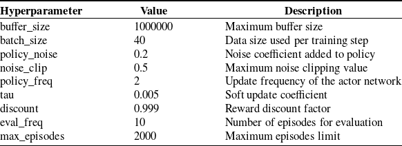
Initially, this study verifies the feasibility of training obstacle avoidance strategy models on the underwater robot system simulation platform. During the training process, each session randomly generates the robot’s initial position, target position, and obstacle locations, with both simple and complex obstacle environments as depicted in Figure 14. Each training episode ends when the robot either reaches the target point or collides with an obstacle, after which rewards are computed and a new episode begins. The hyperparameters used during training are listed in Table V.
Hyperparameter settings.

Convergence verification of autonomous obstacle avoidance training based on simulation training environment.

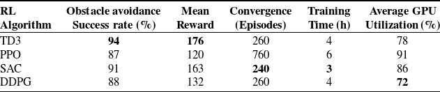
To validate the convergence of DRL algorithms in simulated environments, we first conducted experiments in simplified scenarios. Four mainstream reinforcement learning algorithms—TD3, PPO [Reference Schulman, Wolski, Dhariwal, Radford and Klimov29], SAC [Reference Haarnoja, Zhou, Abbeel and Levine11], and DDPG [Reference Lillicrap, Hunt, Pritzel, Heess, Erez, Tassa, Silver and Wierstra22]—were comparatively analyzed for robot obstacle avoidance tasks. The reward curves obtained during training are illustrated in Figure 15, while the performance metrics are summarized in Table VI. TD3 demonstrated superior performance with the highest obstacle avoidance success rate (94%) and mean reward (176), requiring a moderate 4 h of training with 78% GPU utilization. SAC exhibited advantages in training efficiency, converging in 3 h and 240 episodes, while achieving the second-best avoidance success rate (91%) and reward value (163). In contrast, PPO showed the slowest convergence (760 episodes) with lower mean rewards (120), while DDPG performed moderately across all metrics. Comprehensively, TD3 proved optimal for this study’s robot obstacle avoidance application, effectively balancing successful navigation and training efficiency.
Performance comparison of RL algorithms for robot obstacle avoidance.

5.1.2. Reward function validation
This section of the study continues to evaluate the effectiveness of the proposed reward mechanism. In the comparative experiment setup, the only variable was whether the state-associated reward
 $R_{assoc}$
was enabled, while all other settings remained unchanged. Even without the
 $R_{assoc}$
, the agent could still receive rewards through other components of the reward function. The mobility outcomes of the models generated by both approaches were tested, as shown in Table VII. In five separate tests where the robot’s starting positions were randomized, models without the state-associated reward mechanism exhibited behaviors such as spinning in place or stopping altogether. In contrast, models employing the state-associated reward mechanism operated normally, maintaining movement and exploring unknown areas. For the unclearly defined obstacle avoidance tasks in this study, setting a state-associated mechanism to promote exploration and progression proved to be a viable approach.
Number of steps with normal movement in 1000 steps.

Using the aforementioned training methods, underwater robots were able to effectively learn obstacle avoidance strategies in both simple and complex virtual environments, with the convergence of rewards illustrated in Figure 16. After continuous learning, the number of collisions gradually decreased, and the robots increasingly adapted to special situations in the environment, such as dead ends and narrow gaps, ultimately forming a robust obstacle avoidance strategy. The avoidance strategies trained in the virtual environment were tested, as shown in Figure 17, where robots successfully navigated more than 5000 steps in an environment with obstacles without any collisions, proving the effectiveness of the decision-making algorithms and training system.
Training process using association-state reward mechanism: (a) simple, (b) complex.

Autonomous obstacle avoidance test: (a) robot avoiding obstacles, (b) robot motion trajectory.

5.2. Real-environment validation
To ultimately validate the feasibility of transferring the strategies trained through the process described in this paper to the real robot, the autonomously trained obstacle avoidance strategies were directly deployed on a real underwater robot for obstacle avoidance experiments. These experiments were conducted in a swimming pool set up with three different conditions: no obstacles, single obstacle, and double obstacles, as illustrated in Figure 18. Tests were conducted in a pool setting with no obstacles, single obstacle, and dual obstacles. Cameras were mounted above the pool to capture panoramic images and record the robot’s motion trajectory, and the robot was equipped with an electronic compass to record its absolute heading.
The robot commenced from the edge of the pool, autonomously exploring and avoiding obstacles. In the obstacle-free pool, the robot moved toward the direction away from the pool walls and successfully executed a turnaround maneuver. In the single-obstacle pool, upon detecting the obstacle ahead, the robot changed direction, safely navigated around the obstacle, and then returned to a faster speed in a more open area. In the dual-obstacle pool, the robot smoothly maneuvered around the first obstacle and proceeded between the two obstacles. Upon reaching the narrow end of the pool, the robot slowly completed an autonomous turnaround and returned at a low speed. Ultimately, the robot completed multiple movements in the pool without any collisions, with changes in the robot’s heading angle during the process as shown in Figure 19.
Robot motion trajectory in the pool: (a) no obstacles, (b) single obstacle, (c) double obstacles.

Robot heading angle variation: (a) no obstacles, (b) single obstacle, (c) double obstacles.

Based on the experimental observations, it is possible to conclude the impact of the reward settings on the robot’s movement behavior:
-
1. Priority on Obstacle Avoidance: The robot prioritizes avoiding obstacles, slowing its movements when approaching them. This ensures that collision avoidance is maintained as the primary objective, reflecting a cautious strategy that adapts to the proximity of obstacles.
-
2. Enhanced Movement Efficiency: Under the premise of obstacle avoidance, the robot is capable of increasing its movement speed to enhance mobility efficiency. This aspect of the reward function encourages the robot not only to avoid obstacles but also to optimize its path for quicker navigation, balancing safety with speed.
-
3. Continuous Exploration of New States: The robot consistently achieves different states from the previous phases, which promotes exploration of unknown areas. Even when maneuvering into dead ends, the robot maintains its mobility and gradually finds its way out. This demonstrates the robot’s ability to adapt to complex environments and its effectiveness in handling scenarios that require complex navigational decisions.
6. Conclusion
Underwater robots exhibit exceptional maneuverability and autonomy, offering broad application prospects. This paper addressed challenges in underwater robot obstacle avoidance training by developing a high-fidelity simulation system based on mathematical modeling. We examined differences between simulation and real systems, suggesting improvements in system modeling, state acquisition, action execution, and domain representation. To enhance training efficiency, we proposed a state-associated reward mechanism. After training with DRL algorithms, the robot’s effective movement improved by 82.24% during 1000-step motion tests, with a 94% obstacle avoidance success rate. The robot demonstrated safe autonomous navigation for extended periods, balancing environmental exploration with effective obstacle avoidance in unknown environments. Testing the approach on a physical underwater robot in pool experiments across three underwater scenarios demonstrated reasonable obstacle avoidance performance and validated the feasibility of our sim-to-real methods.
While our proposed obstacle avoidance training and transfer methods offer some reference value for underwater mobile robot autonomous navigation research, certain limitations remain in the current work. Due to facility constraints, we have only verified the feasibility of transferring obstacle avoidance strategies to real robots in simple pool environments. In future work, we intend to conduct validation in more complex real-world environments, such as underwater bridge piers and dams that require actual maintenance. These scenarios will demand greater robustness from robot motion strategies. Consequently, we plan to investigate the combined application of robust controllers with deep reinforcement learning algorithms by introducing controllers as intermediate layers to buffer against environmental uncertainties, thereby expanding deployment feasibility across a wider range of application scenarios.
Author contributions
The contributions of the authors to this paper are as follows: Suohang Zhang performed the simulations, data analysis, and wrote the initial draft of the manuscript; Luning Zhang conceived and designed the study; Yanhu Chen contributed to the study design and manuscript revision. All authors reviewed and approved the final version of the manuscript.
Financial support
This work was supported by the National Natural Science Foundation of China (No. 52375032), the Natural Science Foundation of Zhejiang Province (No. LZ25E090001), and the Ningbo Science and Technology Innovation 2025 Major Special Project (No. 2021Z079).
Competing interest
The authors declare that they have no known competing financial interests or personal relationships that could have appeared to influence the work reported in this paper.