1. INTRODUCTION
High-power sources of ultrawideband (UWB) radiation find wide application for investigations of electronic systems susceptibility (Nitsch et al., Reference Nitsch, Camp, Sabath, ter Haseborg and Garbe2004; Bieth et al., Reference Bieth, Schunck, Pinguet and Delmote2014), biological effects (Schunck et al., Reference Schunck, Bieth, Pinguet and Delmote2014), in radar with high space resolution for detection and recognition of objects (Taylor, Reference Taylor and Taylor2001; Koshelev, Reference Koshelev2007) and in ionospheric measurements (Dunham et al., Reference Dunham, Light and Holden1995). UWB radiation pulses with linear and elliptical polarization of the field are required for different applications. The main parameter characterizing UWB radiation sources is an effective potential (or figure-of-merit, Agee et al., Reference Agee, Baum, Prather, Lehr, O'Loughlin, Burger, Schoenberg, Scholfield, Torres, Hull and Gaudet1998) determined as the product of the peak electric field strength E p by the distance r in the far-field zone (rE p). The important characteristics of UWB sources are also the pulse repetition rate and the time of continuous operation (Bieth et al., Reference Bieth, Schunck, Pinguet and Delmote2014).
For UWB pulses with linear polarization, the following types of antennas are used: Impulse Radiating Antenna with a large-diameter reflector (Giri et al., Reference Giri, Lackner, Smith, Morton, Baum, Marek, Prather and Scholfield1997; Sabath et al., Reference Sabath, Nitsch, Jung and Weise2002; Baum et al., Reference Baum, Baker, Prather, Lehr, O'Loughlin, Giri, Smith, Altes, Fockler, McMillan, Abdalla and Skipper2004), TEM antennas (Pokryvailo et al., Reference Pokryvailo, Yankelevich and Shapiro2004; Delmote & Martin, Reference Delmote, Martin, Sabath, Giri, Rachidi and Kaelin2010), and combined antennas KA with the extended frequency band (Koshelev et al., Reference Koshelev, Buyanov, Andreev, Plisko and Sukhushin2001; Andreev et al., Reference Andreev, Buyanov and Koshelev2005). On the basis of the single KA and arrays (2 × 2, 4 × 4, 8 × 8) excited by bipolar pulses of the length 0.2–3 ns, the high-power sources of UWB radiation have been created (Gubanov et al., Reference Gubanov, Efremov, Koshelev, Kovalchuk, Korovin, Plisko, Stepchenko and Sukhushin2005; Efremov et al., Reference Efremov, Koshelev, Kovalchuk, Plisko and Sukhushin2007; Reference Efremov, Koshelev, Kovalchuk, Plisko and Sukhushin2011, Reference Efremov, Koshelev, Kovalchuk and Plisko2013, Reference Efremov, Koshelev, Kovalchuk, Plisko and Sukhushin2014; Andreev et al., Reference Andreev, Efremov, Koshelev, Kovalchuk, Plisko and Sukhushin2011a, Reference Andreev, Efremov, Koshelev, Kovalchuk, Plisko and Sukhushinb) with the effective potential of up to 4.3 MB at the pulse repetition rate of 100 Hz. In all these UWB sources an open-circuit bipolar pulse former (BPF) was used. The circuit of the BPF was originally suggested in (Andreev et al., Reference Andreev, Gubanov, Efremov, Koshelev, Korovin, Kovalchuk, Kremnev, Plisko, Stepchenko and Sukhushin2003).
UWB pulses with elliptical or circular polarization allow testing electronic systems at different positions of the electric field vector E relative to an object thus attracting researchers. To date, high-power radiation sources with elliptical and circular polarization have been created on the basis of excitation of single cylindrical helical antennas with voltage pulses of the damped-sinusoid-type (Giri et al., Reference Giri, Tesche, Abdalla, Skipper and Nyffeler2010), and with monopolar (Mayes et al., Reference Mayes, Mayes, Nunnally and Hatfield2009; Morton et al., Reference Morton, Banister, DaSilva, Levine, Naff, Smith, Sze, Warren, Giri, Mora, Pavlinko, Schleher and Baum2010) and bipolar (Delmote et al., Reference Delmote, Pinguet, Bieth, Sabath and Mokole2014; Andreev et al., Reference Andreev, Efremov, Koshelev, Kovalchuk, Petkun, Sukhushin and Zorkaltseva2014) pulses.
To reduce the width of the pattern and to increase the peak strength of the field E p at a given distance r, or to increase the distance r at a given peak strength of the field E p, it is necessary to develop UWB sources based on multielement arrays. Array structures of combined and helical antennas are different due to the difference of physical processes of radiation.
The first array (2 × 2) of cylindrical helical antennas (Harris, Reference Harris1953, Reference Harris and Jasik1961) was created to radiate harmonic oscillations. The main problem was to choose the distance between the array elements. On the basis of the estimations of the power gain available at that period of time, the chosen distance between the elements was d = 1.5 λ, where λ is the radiation wavelength. According to this approach, the distance was long increasing with the number of the helix turns. It was necessary to increase the number of turns in order to increase the strength of the radiated field (Giri et al., Reference Giri, Tesche, Abdalla, Skipper and Nyffeler2010). Long distances result in side lobes at synchronous excitation of antennas and restrict wave beam steering at wide angles due to diffraction lobes.
In the КА arrays, the distance d = (0.5–0.6) λ0, where λ0 is the central wavelength of the spectrum of a bipolar voltage pulse at the antenna input and, respectively, of the radiated pulse.
The goal of the work is to study and develop a high-power source of UWB radiation with elliptical polarization based on the excitation of a 2 × 2 array of cylindrical helical antennas with a bipolar voltage pulse of the length 1 ns with a reduced distance between the elements.
2. SOURCE STRUCTURE
The structure of a high-power source of UWB radiation with elliptical polarization consists of the following main components: A SINUS-160 monopolar pulse generator, an open-circuit bipolar pulse former, a wave transformer of 50/12.5 Ω impedances, a four-channel power divider, 50 Ω cable feeders with insulating cord, and a radiator presenting a 2 × 2 array of helical antennas in dielectric containers. Figure 1 presents the physical configuration of the source.
Physical configuration of the source: (1) Monopolar pulse generator, (2) bipolar pulse former, (3) wave transformer, (4) power divider, (5) cable feeders, and (6) antenna array.

A bipolar voltage pulse generator of the length 1 ns including a SINUS-160 monopolar pulse generator and an open-circuit BPF was described in detail previously (Andreev et al., Reference Andreev, Efremov, Koshelev, Kovalchuk, Petkun, Sukhushin and Zorkaltseva2014) and will not be discussed here. A bipolar voltage pulse was supplied from the BPF output to the wave transformer input to match the BPF and feeder system of the array. The wave transformer, power divider, and cables with insulating cord were filled with SF6 gas at a pressure of 5 atm to provide electrical insulation. The length of the wave transformer was chosen from the preliminary calculations to be equal to 1.5 of the central wavelength λ0 = τpc of the spectrum of a bipolar pulse length τ p = 1 ns, where c is the velocity of light. Test measurements have shown that loss of power (energy) in the feeder system including a wave transformer, a power divider and cables equals approximately to 8%. The bipolar pulse length at the output of the feeder system increases by 40 ps compared with the input pulse.
The radiator is a square 2 × 2 array consisting of identical cylindrical helical antennas. The distance between the axes of the elements in the array in the vertical and horizontal directions is d = 21 cm. The average diameter of the helical antenna 2b = 95.5 mm, the inter turn distance S = 67.4 mm, and the number of coils N = 4.5. The helix perimeter С is 2πb = 30 cm that corresponds to λ0. The helix is made of a 10 mm diameter copper tube. Note that the structure of the helical antenna has been modified in comparison with the previous one (Andreev et al., Reference Andreev, Efremov, Koshelev, Kovalchuk, Petkun, Sukhushin and Zorkaltseva2014). Namely, the helix perimeter was increased from 26.7 to 30 cm that corresponds to the central wavelength λ0, and the number of coils was increased from 4 to 4.5. The preliminary measurements of the voltage standing wave ratio (VSWR) for single antennas with a ground plate (GP) of the diameter 30 cm and number of coils N = 4; 4.25; 4.5 have shown that the lower frequency boundary by the VSWR level equal to 2 for the antenna with N = 4.5 is shifted by 50 MHz to the low frequency region, which increases the energy efficiency of the radiator.
The matching between the 50 Ω cable feeder and impedance of the helical antenna was provided by means of the transforming line presenting a part of the first coil. The total length of the antenna counted from the GP was L a = 32.8 cm. The array elements were disposed on a square 51 × 51 cm2 GP, the corners of which were rounded by the radius of 15 cm. The antennas were placed in the thin-wall fiberglass radio transparent containers filled with SF6 gas at a pressure of 3 atm to provide electrical insulation.
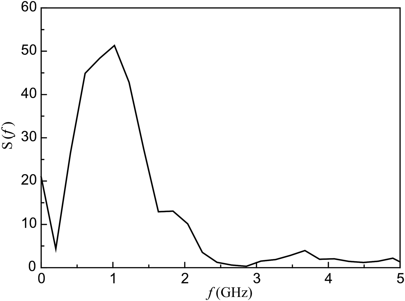
The UWB source can operate both in a single pulse mode and at the pulse repetition rate adjustable in the limits of 1–100 Hz. Special studies of the BPF gas discharges allowed improving the bipolar pulse characteristics in comparison with the previous ones (Andreev et al., Reference Andreev, Efremov, Koshelev, Kovalchuk, Petkun, Sukhushin and Zorkaltseva2014). Namely, the pulse symmetry has been improved and its amplitude has been increased. Figure 2 presents the waveform of the pulse. The pulse had the amplitude of 225 kV and the length of 1 ns at the level of 0.1. Figure 3 presents the amplitude spectrum of the pulse. The maximum of the spectrum corresponds to the frequency of 1 GHz, and, respectively, λ0 = 30 cm.
Waveform of the output bipolar voltage pulse.

Amplitude spectrum of the bipolar voltage pulse.

3. CHARACTERISTISTICS OF HELICAL ANTENNA ARRAYS
An important parameter of the array is the distance between the elements d. Here, we use empirical estimations of d (King & Wong, Reference King and Wong1980; King et al., Reference King, Wong, Newman and Volakis2007) for a square array excited by harmonic oscillations at the wavelength λp corresponding to the maximum of the antenna gain. Since the main fraction of radiated energy of the UWB pulse is concentrated near the central wavelength λ0, then in our estimations we substitute λp for λ0:
 $$d = \sqrt {{G / {4{\rm \pi}}}} {{\rm \lambda} _0},$$
 $$G = 8.3{\left( {\displaystyle{C \over {{{\rm \lambda} _0}}}} \right)^{\sqrt {N + 2} - 1}}{\left( {\displaystyle{{NS} \over {{{\rm \lambda} _0}}}} \right)^{0.8}}{\left[ {\displaystyle{{tg12.5^\circ} \over {tg{\rm \alpha}}}} \right]^{{{\sqrt N} / 2}}}.$$
Here G is the single antenna gain, α is the helix winding angle. The optimum distance for the above mentioned antenna parameters is d = 0.8λ0. Note that the estimation by the previous formula for G (Harris, Reference Harris1953, Reference Harris and Jasik1961) gives the value d = 1.1λ 0. For the developed array the distance d = 0.7λ0was chosen. Further reduction of d was limited by the structure of the dielectric container.
Preliminary, frequency- and time-domain measurements of the array elements mounted on the GP of the dimension 51 × 51 cm2 as well as of the whole 2 × 2 array were performed. In the frequency-domain measurements, an Agilent N5227A vector network analyzer with the frequency band ranging from 10 MHz to 67 GHz was used. In the time-domain measurements a low-voltage bipolar pulse generator of the amplitude 27 V and length 1 ns was used. The measurements were performed in an anechoic chamber. In the low-voltage measurements we used a crossed-dipole antenna (Balzovskii et al., Reference Balzovskii, Buyanov and Koshelev2010) for simultaneous recording of the orthogonal components of the field and a LeCroy Wave Master 630Zi-A oscilloscope with the frequency band of 30 GHz.
Prior to the measurements of radiation characteristics, it is necessary to evaluate the position of the radiation center to L c relative to the GP and the far-field boundary r ff. Methods of determining these parameters are described in detail for a single helical antenna excited by a bipolar pulse of the length 1 ns (Andreev et al., Reference Andreev, Efremov, Koshelev, Kovalchuk, Petkun, Sukhushin and Zorkaltseva2014). The measurements were carried out along the array axis. The waveforms of the radiated field were recorded in two mutually perpendicular planes X and Y. By the results of the measurements, the hodograph of the electric field vector E was plotted and the values of E p as well as the axial ratio (AR) were determined. The positions of the radiation center and far-field boundary were estimated from the conditions of rE p ≈ const and AR ≈ const, correspondingly.
Figure 4 presents the measurement results for estimation of the radiation center position. Curve 1 corresponds to the dependence rE p(r) counted from the GP position. Curve 2 corresponds to the dependence rE p(r) counted from the helix end. Curve 3 corresponds to the dependence rE p(r) counted from the point placed at a distance r = 20 cm from the GP. For convenience, all the curves are re-counted so that the distance r should be counted from the GP. As it follows from the data obtained, the array radiation center is in existence. It is located at a distance L c = 20 cm that corresponds to L c/L a = 0.6. The distance at which the condition rE p ≈ const is satisfied equals approximately to 2 m.
rE p value versus the distance counted from the GP (1), helix end (2), and L c (3).

Figure 5 presents the measurement results of the value AR versus the distance counted from the GP. According to the criterion AR ≈ const, the far-field boundary r ff is located at a distance of approximately 3.5 m from the GP and the value AR = 1.35. The measurements results (Fig 4, curve 3) have shown that the electric field strength changes as 1/r from the distance r = 2 m. From the estimation of the far-field boundary for the main part of the radiation energy (Andreev et al., Reference Andreev, Efremov, Koshelev, Kovalchuk, Plisko and Sukhushin2011a, Reference Andreev, Efremov, Koshelev, Kovalchuk, Plisko and Sukhushinb) it follows that r = 1.2 m according to the formula
 $$r = \displaystyle{{2{D^2}} \over {{{\rm \lambda} _0}}},$$
where D is the maximum transverse dimension of the GP. This distance is counted from the radiation center L c. Taking this into account, the distance to the far-field boundary counted from the GP is r = 1.4 m. Our numerous studies fulfilled previously have shown that the estimations of the far-field boundary by the criterion rE p ≈ const and formula (2) correspond to each other and valid for the UWB radiation sources with linear polarization. For elliptically polarized radiators, the far-field boundary is determined according to the criterion AR ≈ const and its value r ff exceeds the previously obtained estimations for the antenna arrays with linearly polarized radiation.
AR value versus the distance.

To check the validity of the relation (1), the interactions of array elements have been studied. For this purpose, the following three parameters have been measured: VSWR, radiated field hodographs, and efficiency by the peak field strength.
As it follows from the measurements, VSWR of the single antenna and of the array element at a 51 × 51cm2 GP practically coincide. In the measurements of the VSWR array element, all the remaining antennas were connected with the 50 Ω resistive loads. The measurement results for the investigated element in the array remained unchanged if three other antennas in the array were disconnected from the resistive loads (idle mode). Figure 6 presents VSWR versus frequency for the element of the array without a dielectric container (1) and the array of antennas with the dielectric containers (2). The array VSWR was measured at the input of the feeder system (wave transformer). From the data obtained it follows that the feeder system of the array results in the VSWR increase and, accordingly, to the energy loss that agrees with the above mentioned test measurements. As it follows from the measurements carried out, dielectric containers have no significant effect on the radiation characteristics.
VSWR versus frequency for array element without dielectric container (1), and array of antennas with dielectric containers (2).

Measurements of the radiated field at the array axis in the far-field zone were made successively for one, two, three elements, and the whole array of 2 × 2. During radiation of one, two, and three array elements the remaining cables were connected to the resistive loads of 50 Ω. The hodographs were plotted for each case (Fig. 7). The studies have shown that the pulses are summated synchronously and the amplitudes are increased in a strict proportion to the number of the elements. The hodographs of one element as well as of two, three elements, and the 2 × 2 array were close to each other. A slight difference of the hodographs was observed for radiation of one and two elements. Subsequent increase of the number of elements resulted in no noticeable changes of the hodograph.
Hodographs of the electric field strength vector radiated by one (а), two (b), and three (c) elements and the array (d).

Measurements of the efficiency by the peak field strength k E = rE p/U gmax determined as the ratio of the effective potential of radiation to the bipolar voltage pulse amplitude at the input of the element and array, respectively, were performed for one element and the array. The measurements were made on the array axis in the far-field zone. By the results, k E = 1 for one element, and for the array k E = 1.9. However, taking into account the losses in the feeder system, the efficiency of the radiating part of the array k E = 2.
Note that the UWB source has been developed using the circuit in which the wave impedance of the coaxial lines at the output of the BPF and input of the array elements is equal to 50 Ω. For this type of the UWB radiation source, the peak field strength of the array in the absence of energy losses equals to the peak field strength of a single antenna multiplied by  $\sqrt {{N_{\rm t}}} $, where N t is the number of the transmitting antennas in the array. The above mentioned results show that this condition of an ideal array is fulfilled for the array radiator. Therefrom it follows that the energy losses caused by the interaction of the elements in the radiator are absent.
Thus, a series of the measurements carried out points to the absence of interaction of the elements in the array at a distance d = 0.7λ0 between the elements, while the ratio (1) implies the absence of interaction of the elements in the array at long distances.
The important characteristics of the radiator are the pattern and dependence of AR on the angle θ relative to the array axis. Figure 8 presents the array patterns by the peak power for the field component E y in two perpendicular planes: Horizontal (а) and vertical (b). Noncoincidence of the maxima of the patterns with the axis θ = 0 is probably conditioned by the measurement errors. Detailed measurements have shown that the width of the patterns by FWHM in two planes X and Y for two field components E x and E y is in the limits of 27.5°–30°. For convenience, just here, the pictures present the angular dependence of the AR value in two planes. Complex waveform of the AR(θ) curves is possibly caused by the asymmetrical position of one element relative to three other ones in the 2 × 2 array. One can assume that in multielement arrays the curves of AR(θ) will be more symmetrical.
Array pattern by peak power for E ycomponent of the field in horizontal (а) and vertical (b) planes, and corresponding angular dependences of AR values.

4. RADIATION OF HIGH-POWER UWB PULSES
Measurements of characteristics of high-power UWB radiation pulses were carried out in the far-field zone on the source axis (Fig. 1). To record radiation pulses, a receiving TEM antenna and a LeCroy Wave Master 630Zi-A oscilloscope were used. The TEM antenna received the E x – and E y – components of the field depending on its orientation. To measure the time shift between the field components, triggering of the oscilloscope was performed from the signal of an auxiliary antenna, the position of which was unchangeable during the measurements. Simultaneously with radiation recording, the voltage at the BPF output was recorded by means of a Tektronix TDS 6604 oscilloscope with a 6 GHz frequency band.
Figure 9 presents the waveforms of radiation pulses for two field components: E x and E y. Figure 10 presents the hodograph of the electric field strength vector E. The value of AR equals to 1.4. The effective potential of radiation rE p = 440 kV. The efficiency by the peak field strength k E = 1.95, that agrees with the low-voltage measurements.
Waveforms of the E x and E y components of the field at a 4 m distance from the GP.

Hodograph of the electric field strength vector at a 4 m distance from GP.

When the voltage pulse spectrum at the array input (Fig. 3) and VSWR of the array (Fig. 6, curve 2) are known, the array efficiency by the energy k w can be determined similarly (Koshelev & Plisko, Reference Koshelev and Plisko2013; Andreev et al., Reference Andreev, Efremov, Koshelev, Kovalchuk, Petkun, Sukhushin and Zorkaltseva2014) by the formula:
 $$\eqalign{k_{\rm w}& = 1 - \displaystyle{{{W_{{\rm ref}}}} \over {{W_{\rm g}}}} \cr & = 1 - \displaystyle{{\int {U_{\rm g}^2 \left( f \right){{\left( {({K_{\rm V}}\left( f \right) - 1)/({K_{\rm V}}\left( f \right) + 1)} \right)}^2}df}} \over {\int {U_{\rm g}^2 \left( f \right)df}}},}$$
where W ref is the reflected energy, W g is the generator pulse energy, U g(f) is the generator voltage pulse spectrum, and K V is the VSWR of the antenna array in dielectric containers. According to the results obtained, k w = 0.8.
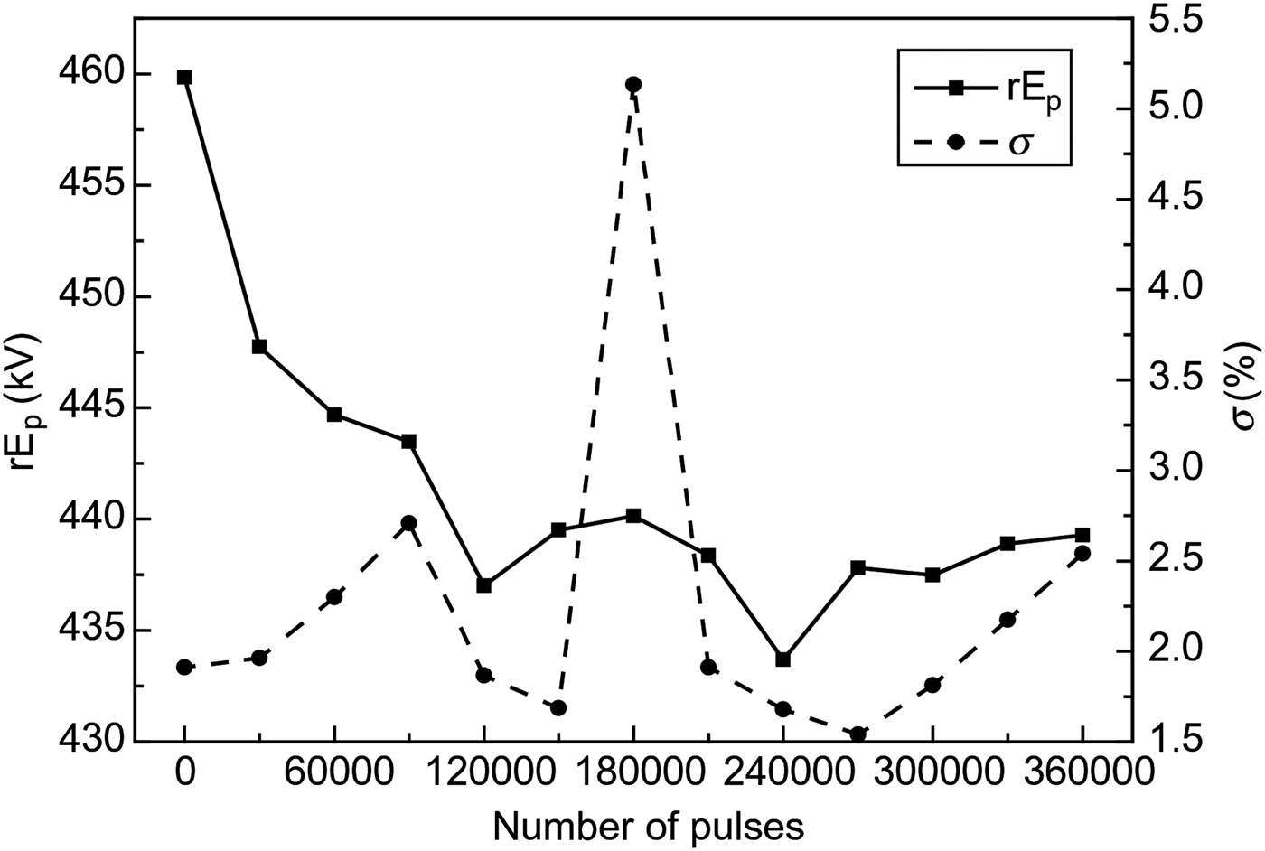
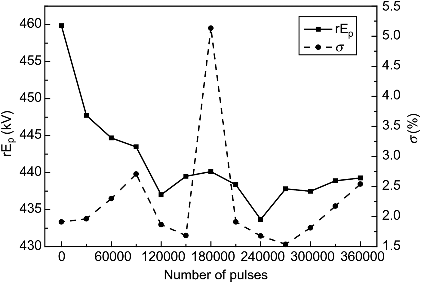
Within 1 h of the UWB source operation at a pulse repetition rate of 100 Hz, the effective potential of radiation and the root-mean-square deviation σ averaged by 100 ps varied in the limits of 5% (Fig. 11).
Effective potential of radiation and its root-mean-square deviation versus the number of pulses.
5. CONCLUSION
A high-power source of UWB radiation with elliptical polarization of the field based on the excitation of a four-element array of cylindrical helical antennas by a bipolar voltage pulse of the amplitude 225 kV and length 1 ns has been created. The high-energy efficiency of the array k w = 0.8 was demonstrated. Radiation pulses with the effective potential of 440 kV were obtained at a pulse repetition rate of 100 Hz at high stability.
On the basis of the performed experimental studies, it is shown that it is incorrect to use the ratio (1) for choosing the distance between the array elements of helical antennas. The distance can be decreased allowing constructing compact arrays. To determine minimum distances requires additional studies. Pulses of elliptically polarized radiation with axial symmetry of AR require significant increase of the number of elements in the array.
Existence of the center of radiation in the array of cylindrical helical antennas excited by a bipolar voltage pulse was demonstrated experimentally. The far-field boundary for the elliptically polarized radiation is located at longer distances than for the linearly polarized radiation.
ACKNOWLEDGEMENTS
The authors are grateful to E.V. Balzovsky for his help with the measurements. The work was supported by the Basic Research Program of the Presidium of RAS “Fundamental problems of pulsed high-current electronics”.