






1. Introduction
Self-organisation of living systems is one of Nature's most ubiquitous and mesmerising phenomena. It arises across a wide range of spatial and temporal scales, from the cells in our bodies (George, Bullo & Campàs Reference George, Bullo and Campàs2017) and swarming of microorganisms (Koch & Subramanian Reference Koch and Subramanian2011), to the flocking of birds (Lissaman & Shollenberger Reference Lissaman and Shollenberger1970) and schooling of fish (Weihs Reference Weihs1973). For macroscopic flyers and swimmers, a wide range of hypotheses have attributed collective behaviour to social interactions (Wynne-Edwards Reference Wynne-Edwards1962), protection against predators (Tinbergen Reference Tinbergen2012), food prospect optimisation (Pitcher, Magurran & Winfield Reference Pitcher, Magurran and Winfield1982), and/or energetic benefits (Weihs Reference Weihs1973, Reference Weihs1975). Our knowledge of the latter hypothesis is limited since it is regulated by complex hydrodynamic interactions. Yet both the spatial organisation (Lissaman & Shollenberger Reference Lissaman and Shollenberger1970; Badgerow & Hainsworth Reference Badgerow and Hainsworth1981) and temporal synchronisation (Drucker & Lauder Reference Drucker and Lauder2001; Portugal et al. Reference Portugal, Hubel, Fritz, Heese, Trobe, Voelkl, Hailes, Wilson and Usherwood2014; Ashraf et al. Reference Ashraf, Bradshaw, Ha, Halloy, Godoy-Diana and Thiria2017) have emerged as factors influencing the hydrodynamic interactions, and consequently the energetic cost of locomotion and travelling speed of individuals in a collective.
Still, our understanding of the force production and energetics of schooling swimmers is mostly limited to canonical spatial formations such as a leader–follower in-line formation (Streitlien, Triantafyllou & Triantafyllou Reference Streitlien, Triantafyllou and Triantafyllou1996; Akhtar et al. Reference Akhtar, Mittal, Lauder and Drucker2007; Boschitsch, Dewey & Smits Reference Boschitsch, Dewey and Smits2014; Muscutt, Weymouth & Ganapathisubramani Reference Muscutt, Weymouth and Ganapathisubramani2017; Kurt & Moored Reference Kurt and Moored2018a; Heydari & Kanso Reference Heydari and Kanso2021) and a side-by-side formation (Dewey et al. Reference Dewey, Quinn, Boschitsch and Smits2014; Quinn et al. Reference Quinn, Moored, Dewey and Smits2014; Ashraf et al. Reference Ashraf, Bradshaw, Ha, Halloy, Godoy-Diana and Thiria2017; Kurt & Moored Reference Kurt and Moored2018b). The hydrodynamic performance of in-line formations is dictated by the synchronisation between the vortices shed from the upstream leading swimmer and the motion of the downstream following swimmer, which leads to a sinusoidal variation in the follower performance as the separation distance is varied (Boschitsch et al. Reference Boschitsch, Dewey and Smits2014; Kurt & Moored Reference Kurt and Moored2018a; Alaminos-Quesada & Fernandez-Feria Reference Alaminos-Quesada and Fernandez-Feria2020, Reference Alaminos-Quesada and Fernandez-Feria2021; Arranz, Flores & Garcia-Villalba Reference Arranz, Flores and Garcia-Villalba2022; Baddoo et al. Reference Baddoo, Moore, Oza and Crowdy2023). Thus the leader's wake wavelength can be chosen as the characteristic length scale to non-dimensionalise the separation distance (Ramananarivo et al. Reference Ramananarivo, Fang, Oza, Zhang and Ristroph2016; Newbolt, Zhang & Ristroph Reference Newbolt, Zhang and Ristroph2019; Alaminos-Quesada & Fernandez-Feria Reference Alaminos-Quesada and Fernandez-Feria2021; Arranz et al. Reference Arranz, Flores and Garcia-Villalba2022), and the optimal phase difference to maximise the performance benefits of schooling follows a linear relationship with this dimensionless distance (Boschitsch et al. Reference Boschitsch, Dewey and Smits2014; Portugal et al. Reference Portugal, Hubel, Fritz, Heese, Trobe, Voelkl, Hailes, Wilson and Usherwood2014; Kurt & Moored Reference Kurt and Moored2018a; Li et al. Reference Li, Nagy, Graving, Bak-Coleman, Xie and Couzin2020). In in-line formations, the leader is typically unaffected by the presence of the follower except when they are compact and the follower is within one wake wavelength of the leader (Boschitsch et al. Reference Boschitsch, Dewey and Smits2014; Kurt & Moored Reference Kurt and Moored2018a; Kurt, Mivehchi & Moored Reference Kurt, Mivehchi and Moored2021). Side-by-side formations are also greatly influenced by the phase synchrony between swimmers (Dong & Lu Reference Dong and Lu2007; Raspa, Godoy-Diana & Thiria Reference Raspa, Godoy-Diana and Thiria2013; Bao et al. Reference Bainbridge2017; Godoy-Diana et al. Reference Godoy-Diana, Vacher, Raspa and Thiria2019), and for two swimmers with anti-phase kinematics the problem is analogous to swimming near a solid boundary for inviscid flows, for which performance benefits can be achieved (Zhong et al. Reference Zhong, Han, Moored and Quinn2021; Han et al. Reference Han, Zhong, Mivehchi, Quinn and Moored2023). In recent years, more attention has been paid to staggered, diamond and rectangular formations that can exhibit features and performance benefits observed in both in-line and side-by-side formations (Dai et al. Reference Dai, He, Zhang and Zhang2018; Peng, Huang & Lu Reference Peng, Huang and Lu2018; Verma et al. Reference Verma, Novati, Koumoutsakos and Sethian2018; Oza, Ristroph & Shelley Reference Oza, Ristroph and Shelley2019; Kurt, Panah & Moored Reference Kurt, Panah and Moored2020; Alben Reference Alben2021; Arranz et al. Reference Arranz, Flores and Garcia-Villalba2022; Newbolt, Zhang & Ristroph Reference Newbolt, Zhang and Ristroph2022; Pan & Dong Reference Pan and Dong2022; Baddoo et al. Reference Baddoo, Moore, Oza and Crowdy2023; Kelly et al. Reference Kelly, Pan, Menzer and Dong2023; Kelly & Dong Reference Kelly and Dong2024).
In the existing literature, it is commonly presumed that the spatial organisation observed in schools is driven by animals’ interest to maximise swimming efficiency or force production. However, another explanation was first proposed by Sir James Lighthill (Reference Lighthill1975). The so-called Lighthill conjecture (Ramananarivo et al. Reference Ramananarivo, Fang, Oza, Zhang and Ristroph2016) postulates that the formations of fish in a school may be due to the interaction forces that push and pull the swimmers into a particular stable formation, much like the atoms in a crystal lattice. Indeed, this idea of passive self-organisation has shown promise in recent studies where one-dimensional (1-D) streamwise stability has been observed in schools of up to five in-line self-propelled foils (Becker et al. Reference Becker, Masoud, Newbolt, Shelley and Ristroph2015; Ramananarivo et al. Reference Ramananarivo, Fang, Oza, Zhang and Ristroph2016; Newbolt et al. Reference Newbolt, Lewis, Bleu, Wu, Mavroyiakoumou, Ramananarivo and Ristroph2024) or in small schools of various formations (Dai et al. Reference Dai, He, Zhang and Zhang2018; Peng, Huang & Lu Reference Peng, Huang and Lu2018; Newbolt et al. Reference Newbolt, Zhang and Ristroph2022), as well as in pairs of in-line hydrofoils with differing kinematics (Newbolt et al. Reference Newbolt, Zhang and Ristroph2019). While these studies have shown seminal results supporting the Lighthill conjecture, they have only probed the 1-D stability of formations. However, two-dimensionally or even three-dimensionally stable formations are required for the passive self-organisation of schools that produce two-dimensional (2-D) or three-dimensional (3-D) flows. In fact, 2-D stability of two pitching hydrofoils has been found, albeit in 2-D simulations at low Reynolds numbers ( $\mbox{Re} = 200$) outside the inertial range typical of adult fish (Muller, van den Boogaart & van Leeuwen Reference Muller, van den Boogaart and van Leeuwen2008; Van Rees, Gazzola & Koumoutsakos Reference Van Rees, Gazzola and Koumoutsakos2013). This suggests that 2-D stability may apply to hydrofoils and, ultimately, fish schools, yet this still has to be established in biologically relevant regimes of 3-D inertial flows.
Here, we advance our understanding of the hydrodynamic interactions of schooling inertial swimmers in two ways. First, we measure the 2-D stability of schooling formations for constrained 2-D and freely swimming 3-D foils, which takes us closer to understanding the role of the Lighthill conjecture in schooling formations. We discover that many of the one-dimensionally stable formations previously observed are, in fact, unstable once the cross-stream stability is considered. Yet we still find that a side-by-side formation is two-dimensionally stable, providing support for the hypothesis that this formation observed in real fish (Ashraf et al. Reference Ashraf, Bradshaw, Ha, Halloy, Godoy-Diana and Thiria2017) may be due to passive self-organisation. Second, we measure the force production and energetics of two interacting hydrofoils throughout a plane of possible formations ranging from in-line to side-by-side by passing through the possible staggered formations. We reveal that there is a thrust and efficiency optimum in a slightly staggered formation where there is direct vortex impingement on the follower.
2. Methods
To examine the flow interactions that occur in schools, full swimmer models can be readily used in numerical studies (Verma et al. Reference Verma, Novati, Koumoutsakos and Sethian2018); however, these models are difficult to implement experimentally. Instead, experiments typically use oscillating hydrofoils as a simple model of the propulsive appendages of animals (Boschitsch et al. Reference Boschitsch, Dewey and Smits2014; Dewey et al. Reference Dewey, Quinn, Boschitsch and Smits2014; Quinn et al. Reference Quinn, Moored, Dewey and Smits2014; Becker et al. Reference Becker, Masoud, Newbolt, Shelley and Ristroph2015; Ramananarivo et al. Reference Ramananarivo, Fang, Oza, Zhang and Ristroph2016; Muscutt et al. Reference Muscutt, Weymouth and Ganapathisubramani2017; Kurt & Moored Reference Kurt and Moored2018a; Kurt et al. Reference Kurt, Cochran-Carney, Zhong, Mivehchi, Quinn and Moored2019, Reference Kurt, Panah and Moored2020; Newbolt et al. Reference Newbolt, Zhang and Ristroph2019). Importantly, these oscillating hydrofoils capture the salient unsteady fluid mechanics of the added mass forces, circulatory forces and shed vortices.
2.1. Constrained foil experiments
Following this simple model approach, experiments were conducted for a minimal school or a minimal collective of a pair of sinusoidally pitching hydrofoils constrained in space and immersed in a closed-loop water channel (test section with  $2.4$ m length,
 $0.91$ m width,
 $0.61$ m depth). A constant flow speed
 $U=0.093\ {\rm m}\ {\rm s}^{-1}$ was imposed, which gives a chord-length-based Reynolds number
 $\mbox{Re}=9950$. Figure 1 shows the constrained-foil set-up installed in the water channel where two actuation mechanisms were secured on aluminium profiles, and a surface and splitter plate were placed near the hydrofoil tips to restrict the flow to be nominally 2-D. The actuation mechanisms oscillated a leader and follower hydrofoil that had rectangular planforms and NACA 0012 cross-sections. Each hydrofoil had chord length
 $c=0.095$ m and span length
 $s=0.19$ m (aspect ratio
 $AR=2$). The hydrofoils were 3-D-printed from acrylonitrile butadiene styrene (ABS) and coated with a layer of clear acrylic paint to prevent water absorption and provide a smooth surface finish. Slider attachments allowed for the manipulation of the hydrofoil positions between experiments. The hydrofoils were moved from in-line to staggered to side-by-side arrangements via the T-shaped slot on the surface plate, as shown in figure 1(b). The distances were normalised by the chord length as
 $X^*=x/c$ and
 $Y^*=y/c$. For streamwise spacings,
 $X^*>1.5$, the follower hydrofoil was secured to a linear traverse system that runs along the streamwise direction, automating the streamwise positioning between the two hydrofoils throughout the experiment. In total, we considered 270 formations, with different grid spacing depending on the proximity between the hydrofoils, as shown in figure 2. Each dot represents the position of the leading edge of the follower relative to the leading edge of the leader.
Schematics of the constrained-foil set-up: (a) side view and (b) top view. (c) The actuation mechanism for the hydrofoils.

Schematic of positions of the follower hydrofoil relative to the leader. Shown is a grid comprised of three different spacings: a fine rectangular grid of  $0.05c$ spacing close to the trailing edge of the leader, in the range
 $1.05 \leq X^* \leq 1.15$,
 $-0.15 \leq Y^* \leq 0.15$; a second region, with ranges
 $-0.2 \leq X^* \leq 2$,
 $0.5 \leq Y^* \leq 0.8$ and
 $1.1 \leq X^* \leq 2$,
 $-0.2 \leq Y^* \leq 0.4$, with a grid of
 $0.1c$ spacing; and a third region farther downstream, with range
 $2.2 \leq X^* \leq 3.8$,
 $-0.1 \leq Y^* \leq 0.8$, with a more coarse grid of
 $0.2c$ spacing. In total, there are 270 grid points.

Each hydrofoil was actuated with sinusoidal pitching motions about an axis located  $8.4$ mm behind their leading edge with a servo motor (Dynamixel MX-64T). The leader hydrofoil was prescribed a sinusoidal pitching motion
 ${\theta }_L(t) = {\theta }_0\sin (2{\rm \pi} f t)$, where
 $f$ is the oscillation frequency, and
 $\theta _0$ is the pitching amplitude. The follower was pitched similarly as
 ${\theta }_F(t) = {\theta }_0 \sin (2{\rm \pi} f t+\phi )$ with fixed phase difference or synchrony
 $\phi = {\rm \pi}$ throughout the study. The peak-to-peak trailing edge amplitude of the hydrofoils can be defined as
 $A =2c\sin (\theta _0)$. The oscillation frequency and the dimensionless amplitude
 $A^* = A/c$ were also fixed throughout the study, at
 $f=0.98$ Hz and
 $A^*=0.25$, which gives a fixed reduced frequency
 $k=fc/U=1$, and a fixed Strouhal number
 $St=fA/U=0.25$. These dimensionless numbers are typical of efficient biological swimming (Webb Reference Webb2002; Gazzola, Argentina & Mahadevan Reference Gazzola, Argentina and Mahadevan2014).
2.2. Force measurements and definition of constrained foil performance metrics
An ATI Nano43 six-axis force sensor was used to measure the thrust, lift and pitching moment acting on each hydrofoil in all of the 270 formations. An optical encoder recorded the angular position, which was then used to compute the angular velocity  $\dot {\theta }$ for each hydrofoil. The total instantaneous power input was then calculated as
 $P_T(t)=M_{\theta }\dot {\theta }$, where
 $M_{\theta }$ denotes the pitching moment. Here, the inertial power was determined from the same experiments conducted in air, and was subtracted from the total power
 $P_T(t)$ to calculate the instantaneous power input to the fluid,
 $P(t)$. Force measurements were taken for 100 oscillation cycles from the leader and follower, and each experiment was repeated 10 times. The time-averaged values were calculated for each of these trials, and their mean from 10 trials was calculated to determine the time-averaged total thrust, lift and power. The profile drag was measured for the static foil in an imposed flow over 20 second intervals. Net thrust was determined by subtracting the profile drag acting on the hydrofoils from the time-averaged thrust:
 $\bar {T}^{{net}} = \bar {T} - \bar {D}$. The definitions of the coefficients of net thrust
 $C_T$, drag
 $C_D$, lift
 $C_L$, and power
 $C_P$, and efficiency
 $\eta$, are given as follows for the individual hydrofoils:
 \begin{equation} C_T = \frac{\bar{T}^{{net}}}{\tfrac{1}{2}\rho {U}^2 c s}, \quad C_D = \frac{\bar{D}}{\tfrac{1}{2}\rho {U}^2 c s},\quad C_L = \frac{\bar{L}}{\tfrac{1}{2}\rho {U}^2 c s}, \quad C_P = \frac{\bar{P}}{\tfrac{1}{2}\rho {U}^3 c s}, \quad \eta = \frac{C_T}{C_P}, \end{equation}
where  $\rho$ is the fluid density, and
 $s$ is the span length of the hydrofoils.
Here, we also report collective performance parameters, i.e. the average performance from the leader and the follower. The collective force and power coefficients, as well as the collective efficiency, are denoted with a  $C$ subscript, and defined as
 \begin{equation} C_{T,C} = \frac{\bar{T}^{{net}}_L + \bar{T}^{{net}}_F}{\rho {U}^2 c s}, \quad C_{L,C} = \frac{\bar{L}_L + \bar{L}_F}{\rho {U}^2 c s}, \quad C_{P,C} = \frac{\bar{P}_L + \bar{P}_F}{\rho {U}^3 c s}, \quad \eta_C = \frac{C_{T,C}}{C_{P,C}}. \end{equation}
Note that here, the performance coefficients were defined with combined propulsor area, i.e.  $2cs$, cancelling the one-half in the denominator. Collective thrust and power coefficients, and efficiency, are reported as normalised values with the corresponding isolated hydrofoil performance metric for comparison, and defined as
 \begin{equation} C_{T}^* = \frac{C_{T,C}}{C^{iso}_{T}}, \quad C_{P}^* = \frac{C_{P,C}}{C^{iso}_{P}}, \quad \eta^* = \frac{\eta_C}{\eta^{iso}}. \end{equation}
Here, the collective performance metrics are compared with the collective of two isolated hydrofoils,  $C^{iso}_{T,C} = C^{iso}_{T}$. The isolated net thrust, drag, power and efficiency are
 $C^{iso}_{T} = 0.10 \pm 0.015$,
 $C^{iso}_{D} = 0.03 \pm 0.002$,
 $C^{iso}_{P} = 0.66 \pm 0.0008$ and
 $\eta ^{iso} = 0.15 \pm 0.022$, respectively.
2.3. Flow field measurements
Particle image velocimetry (PIV) measurements of the flow field were performed in the horizontal plane at the mid-span of the foils. Phase-averaged results were calculated from a total of 100 measurements for each flow field. A total of 16 distinct phases ( $0, {\rm \pi}/8, {\rm \pi}/4,\ldots, 15{\rm \pi} /8$) were captured for all schooling formations. The camera used was an Imager sCMOS (
 $2560\times 2560$ pixels) paired with a lens of 50 mm focal length and f-stop
 $f_\# = 2.8$. Magnification factor 0.135 yields a field of view of
 $3.64c \times 3.07c$. The flow was seeded with hollow metallic coated plastic spheres of diameter
 $11\,\mathrm {\mu }{\rm m}$, and was illuminated by a
 $200\ {\rm mJ}\ {\rm pulse}^{-1}$ Nd:YAG laser. Multi-pass, cross-correlation processing of the raw images was employed to obtain the resulting vector fields, with a final interrogation window of
 $48\times 48$ pixels.
2.4. Unconstrained (free-swimming) foil experiments
The unconstrained foil experiments were conducted on a pair of 3-D hydrofoils that are free-to-move independently of each other in the horizontal  $x$–
 $y$ plane. Figure 3 shows the experimental apparatus detailing the leader and follower platforms. A hydrofoil, servo motor, micro-controller, and on-board battery were housed on each platform, which were independently supported by low-friction dual-axis air-bearing stages. The air bearings ran along stainless steel supporting shafts where the combined weight of the platforms acted as a small but non-negligible bending force. To counteract bending in the shafts, weights were attached to the ends, and the shafts were precision levelled to avoid tilting. These measures were taken to minimise gravitational forces acting upon the swimmers.
Schematics of the apparatus for the unconstrained experiments. (a) Perspective view of the two independent air-bearing platforms and the water channel. (b) Side view of the free-swimming apparatus. The two propulsive foils are shown in red. The drag-generating foils are shown in purple. (c) Top view of the apparatus. The streamwise and cross-stream shafts support the carriage systems in the  $x$–
 $y$ plane. (d) Detailed schematics of one free-swimming carriage, actuation system and embedded electronics.

Each hydrofoil was prescribed a sinusoidal pitching motion about its leading edge using a Dynamixel MX-64AT servo motor as in the constrained experiments. The input kinematic parameters and output variables for the free-swimming experiments are presented in table 1. An Arduino micro-controller was used to control each servo, where wireless start/stop commands were sent via infrared communication. The infrared signals synchronised the two independent hydrofoils and their respective electronic systems. The wireless communication guaranteed that no wires connect the air-bearing platforms to the laboratory-fixed framework, which would create small but non-negligible spring forces acting on the hydrofoils. As in the constrained foil experiments, the hydrofoils had a rectangular planform and a NACA 0012 cross-section; however, in these free-swimming experiments, the hydrofoils had aspect ratio  $AR=3$, and there was no surface or splitter plate, which ensured that the flow remained 3-D. A propulsor aspect ratio
 $AR=3$ is representative of the caudal fins of a large number of fishes. Data for 63 species from Sambilay (Reference Sambilay1990) report a mean aspect ratio
 $AR = 4.2 \pm 1.9$, with median 3.7.
Input kinematic parameter and output data from free-swimming experiments. The equilibrium position is denoted as  $(X^*_{eq}, Y^*_{eq})$, and the origin is defined at the leading edge of the leader.

Laser distance sensors (Baumer OADM 20U2480/S14C and OADM 13U7480-S35A) were used to measure the positions of the two hydrofoils,  $x(t)$ and
 $y(t)$, in time. The sensors were mounted to the framework, and laser beams were aimed at target surfaces connected to the air-bearing platforms. The overall uncertainty in the reported relative positions is smaller than 1 cm. A moving average filter was applied to the time-varying positions over the window of one oscillation period to obtain the cycle-averaged trajectory of the follower. The final equilibrium positions were determined based on the mean position of the last 40 cycles from converged trials. A trial is considered converged if the cycle-averaged position remained within the range
 $\pm 5\,\%$ of the chord length. Due to the latency of the electronic components (IR sensor, Arduino and servo motor), the obtained synchrony
 $\phi$ was different from the prescribed value
 $\phi _{prescribed} = {\rm \pi}$. Here, the reported results achieved synchronies of
 $\phi = {\rm \pi}\pm 2.7\,\%$, or
 $170^{\circ } \leq \phi \leq 190^{\circ }$.
In free-swimming, the swimming speed of the interacting pair of foils,  $U$, can be different from that of an isolated swimmer with identical kinematics,
 $U_{iso}$, and reported as the dimensionless speed
 $u^* = U/U_{iso}$. This speed and its derivative dimensionless numbers (
 $\mbox{Re}$,
 $St$ and
 $k$) are dependent variables, which depend upon the balance of thrust and drag of the swimmer. The thrust–drag balance is represented by the Lighthill number (Moored & Quinn Reference Moored and Quinn2019),
 \begin{equation} Li = C_D S_{wp}, \end{equation}
where  $C_D$ is the free-swimming drag coefficient, and
 $S_{wp} = S_w/S_p$ is an area ratio of the drag-generating wetted area
 $S_w$ to the propulsive planform area
 $S_p$ of the swimmer. For the hydrofoils in the constrained experiments,
 $S_{wp} \approx 2$ since thin hydrofoils have a wetted surface area that is approximately twice their planform area. If the same
 $S_{wp}$ were used for the free-swimming experiments (given the same
 $f$ and
 $A$), then the resulting swimming speed would increase beyond the imposed flow speed of the constrained foils, given that they generate a positive net thrust
 $\bar {T}^{{net}}>0$, leading to lower
 $St$ and
 $k$. In order to achieve
 $St$ and
 $k$ comparable to the constrained-foil experiments, drag-generating foils were attached to the streamwise carriage of the unconstrained foils. Three NACA 0012 foils of
 $AR = 3$ at zero angle of attack were used for this purpose. They had measured drag coefficient
 $C_{D} = 0.035$, and the drag-generating wetted area to propulsive planform area ratio would then be
 $S_{wp} \approx 8$, leading to an estimated Lighthill number
 $Li = 0.28$. The drag-generating foils were positioned sufficiently far away from the leader and the follower to prevent them from disturbing the flow around the foils, at a minimum cross-stream distance of three chords (figure 3), and constrained in the cross-stream direction to ensure that they only generated static profile drag that was virtually independent of the system dynamics. In fact, these drag-generating foils replicated the effect of a virtual drag force introduced in the free-swimming simulations (see § 2.5) since the drag force is transmitted to the system carriage without altering the flow field near the pitching foils.
2.5. Numerical methods
To model the flow over a foil unconstrained in both the streamwise and cross-stream directions, we used a 2-D boundary element method (BEM) based on potential flow theory in which the flow is assumed to be irrotational, incompressible and inviscid. Previously, this method was used to model flow over unsteady hydrofoils (Katz & Plotkin Reference Katz and Plotkin2001; Moored Reference Moored2018; Moored & Quinn Reference Moored and Quinn2019) and their interaction with a solid boundary, and the associated performance for constrained and unconstrained foils (Quinn et al. Reference Quinn, Moored, Dewey and Smits2014; Kurt et al. Reference Kurt, Cochran-Carney, Zhong, Mivehchi, Quinn and Moored2019).
As with the experiments, the freely swimming simulated foils were prescribed sinusoidal pitching motions about their leading edge with an out-of-phase synchrony ( $\phi ={\rm \pi}$). Each foil was assigned a mass, in both the streamwise and cross-stream directions, normalised by their characteristic added mass
 $m^* = m/(\rho sc^2 ) = 2.76$ and
 $1.74$ in each direction, respectively, to match the unconstrained foil experiments. These mass ratios are comparable to biology where, for example,
 $m^* = 3.86$ was the mass ratio calculated for cod (Akoz & Moored Reference Akoz and Moored2018). Note that constrained foils do not exhibit recoil motions, so they have an effectively infinite dimensionless mass,
 $m^*=\infty$. Since the simulated hydrofoils are self-propelled, a drag force
 $D$ was imposed, which is modelled with a high Reynolds number drag law where
 $D = \tfrac 12C_D \rho U^2 S_w$ (Munson, Young & Okiishi Reference Munson, Young and Okiishi1998). The drag force was thus determined by the Lighthill number of the virtual body, which was not present in the computational domain. The Lighthill number in the simulations was set to
 $Li = 0.3$, which was the lowest value achievable for the numerical stability of the current BEM formulation. Further details about the numerical solver can be found in previous work (Kurt et al. Reference Kurt, Cochran-Carney, Zhong, Mivehchi, Quinn and Moored2019; Moored & Quinn Reference Moored and Quinn2019).
For the unconstrained simulations, the time-averaged thrust  $\bar {T}$ was obtained from the pressure forces acting on the swimmer projected in the streamwise direction. Note that for steady-state free-swimming, the time-averaged net thrust is zero, i.e.
 $\bar {T}^{{net}} = \bar {T} - \bar {D} = 0$. The power input to the fluid,
 $P$, was obtained by integrating the inner product between the force vectors
 $\boldsymbol {F}_{e}$ and velocity vectors
 $\boldsymbol {u}_{e}$ of each panel element,
 $e$, along the foil surface
 $S$, as
 $P = -\int _{S} \boldsymbol {F}_{e} \boldsymbol {\cdot } \boldsymbol {u}_{e} \,\mathrm {d}S$.
We can now define the efficiency  $\tilde {\eta }$ for steady-state free-swimming as
 \begin{equation} \tilde{\eta} = \frac{\bar{T}\,\bar{U}}{\bar{P}}, \end{equation}
where the free-swimming propulsive efficiency  $\tilde {\eta }$ is the ratio of the useful locomotive power to the total power input to the fluid and is well defined for steady free-swimming despite the net thrust being zero. This definition is equivalent to that of a constrained foil
 $\eta = \bar {T}^{{net}} \, \bar {U} / \bar {P}$. For the constrained experiments, the net thrust
 $\bar {T}^{{net}}$ is the net propulsive force available to propel a body that generates an equal resistive drag. Note that the efficiency
 $\tilde {\eta }$ is reported only for the unconstrained simulations. Forces and moments were not measured for the free-swimming experiments.
3. Follower force map
In order to probe the Lighthill conjecture in two dimensions, the relative forces acting on the follower in the ( $x$–
 $y$) interaction plane must be examined. This is done by constructing a force map using the constrained-foil measurements.
Consider a frame of reference attached to the leader as in figure 2. The relative lift  $\Delta L$ in the cross-stream direction, and the relative thrust
 $\Delta T$ in the streamwise direction, are defined simply as a difference between the forces acting on the two hydrofoils as
 $\Delta T = T_F - T_L$ and
 $\Delta L = L_F - L_L$, where forces acting on the leader and follower hydrofoils are denoted with subscripts
 $L$ and
 $F$, respectively. Figures 4(a,b) show the relative force conditions that lead to the follower either moving towards or moving away from the leader in the streamwise (
 $x$) and cross-stream (
 $y$) directions.
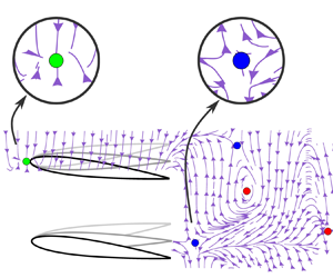
Typical conditions leading to positive and negative relative (a) lift and (b) thrust. (c) Follower force map with an out-of-phase synchrony between the leader and follower, i.e.  $\phi = {\rm \pi}$. The arrows on the force lines indicate the direction in which the follower would move relative to the leader if it were free-swimming. The green, blue and red circles represent the 2-D stable equilibria, the 1-D stable/1-D unstable saddle point equilibria, and the 2-D unstable equilibria, respectively.

First, consider the relative lift for the positive  $x$–
 $y$ plane. The follower is pushed away from the leader in the cross-stream direction (
 $\updownarrow$) when the relative lift force is greater than zero (figure 4a). This condition arises either when lift forces acting on the foils are in the same direction and
 $L_F > L_L$, or when they are acting in opposite directions and pointing away from each other (
 $L_L<0 \downarrow$,
 $L_F>0 \uparrow$). In contrast, the follower is pulled towards the leader when the lift forces are acting in the same direction and
 $L_L > L_F$, or acting in opposite directions and pointing towards each other (
 $L_L>0 \uparrow$,
 $L_F<0 \downarrow$).
Next, consider the relative thrust force in the positive  $x$–
 $y$ plane. A positive relative thrust force (
 $\Delta T>0$) acts to move the follower towards the leader, which arises when
 $T_F>T_L$. In contrast, when
 $T_L>T_F$, the relative thrust force is negative (
 $\Delta T < 0$), and the follower moves away from the leader in the streamwise direction, as shown in figure 4(b). If
 $T_L = T_F$, then the leader and follower swim at the same speed and do not move closer or apart.
To visualise the directions of the relative forces acting on the follower throughout the  $x$–
 $y$ plane, we constructed a force map, which is a novel visualisation made up of force lines (figure 4c). Put simply, the force map conveys the direction that the follower would move in as observed by the leader. The force map is constructed with the origin located at the leading edge of the leader, and a relative force vector (
 $\boldsymbol {F}_{rel} = -\Delta T\,\hat {\boldsymbol {x}} + \Delta L\,\hat {\boldsymbol {y}}$) is determined at each of the measurement positions detailed in figure 2, such that a relative force vector field is created. The resulting vector field is provided in Appendix A. Force lines are then graphed as lines that are everywhere tangent to the local relative force vector field, analogous to streamlines. This novel visualisation tool uses time-averaged force data to visualise the stability characteristics of constrained foils, yet it will be shown to be indicative of the stability characteristics of unconstrained, freely swimming foils.
3.1. Observed equilibria
The force map reveals eight critical points or equilibria where the relative force vector is equal to zero, i.e.  $\Delta T=0$ and
 $\Delta L=0$, which are marked by green, blue and red circles in figure 4(c). The first equilibrium point is located at
 $(X^*, Y^*)=(0, 0.6)$ where the leader and follower are interacting in a side-by-side formation. Interestingly, as the force lines merge at this point, their direction indicates that this equilibrium point is a stable sink point (green circle) in two dimensions. Therefore, when any perturbations move the follower away from this point, forces will arise to return the foil back to this location. Previous low Reynolds number simulations have also shown that side-by-side formations of rigid (Lin et al. Reference Lin, Wu, Zhang and Yang2021, Reference Lin, Wu, Yang and Dong2022) and flexing (Dai et al. Reference Dai, He, Zhang and Zhang2018) foils are two-dimensionally stable, albeit for
 $200 \leq \mbox{Re} \leq 500$, which is outside the inertial regime characteristic of fish schooling. Another critical point is located at
 $(X^*, Y^*)=(1.2, 0)$ in the leader's wake, where the follower is directly in-line with the leader. This represents an equilibrium point that is stable to streamwise perturbations, but unstable to cross-stream perturbations, i.e. an unstable saddle point (blue circles). In fact, there are repeating unstable saddle points in the wake zone (
 $-0.2 \leq Y^* \leq 0.2$) that are spaced one wake wavelength apart, located at
 $X^*= 2.2$ and
 $3.2$. Previous studies (Becker et al. Reference Becker, Masoud, Newbolt, Shelley and Ristroph2015; Ramananarivo et al. Reference Ramananarivo, Fang, Oza, Zhang and Ristroph2016; Newbolt et al. Reference Newbolt, Zhang and Ristroph2019, Reference Newbolt, Zhang and Ristroph2022) have shown that these equilibria are one-dimensionally stable in the streamwise direction; however, we now reveal that they are unstable in the cross-stream direction. Beyond unstable saddle points, there are also equilibrium points that are unstable source points (red circles). These are locations of unstable equilibria in both the streamwise and cross-stream directions, with force lines radiating outwards from them.
3.2. Flow mechanisms behind the stable formation
To understand the flow mechanisms behind the stable side-by-side formation, PIV measurements are employed around the mid-span of the hydrofoils. The flow was seeded with micro-particles, and high-speed cameras were used to capture the motion of the particles consecutively to obtain the instantaneous evolution of the velocity field over one oscillation cycle.
Figure 5(a) presents the vorticity shed from the leader and follower at the stable side-by-side equilibrium at a dimensionless time  $t^* = t/T = 0.5$, where the foils are pitching away from each other. As expected, both foils generate a reverse von Kármán street, which is the signature of thrust production in the wake of the foils. However, due to interaction between the hydrofoils in side-by-side formation, the forming clockwise vortex of the follower and anticlockwise vortex of the leader mutually induce each other in a way that slows their downstream advection. These vortices then pair with their counter-rotating counterparts shed half a cycle later. The pairs mutually induce away from the symmetry line between the foils, leading to momentum jets behind the foils that deflect away from the symmetry line. The deflected jet and vortex pairing mechanism was observed first in Quinn et al. (Reference Quinn, Moored, Dewey and Smits2014) and later in subsequent work (Bao et al. Reference Bao, Zhou, Tao, Peng, Zhu, Sun and Tong2017). The cross-stream stability of the side-by-side formation is mediated by a balance of the wake-induced forces from the deflected jet and the quasi-steady forces, i.e. the body–body flow interaction between the foils (Kurt et al. Reference Kurt, Cochran-Carney, Zhong, Mivehchi, Quinn and Moored2019; Han et al. Reference Han, Zhong, Mivehchi, Quinn and Moored2023).
(a) Vorticity field for the stable side-by-side formation  $X^*=0$,
 $Y^*=0.6$ at
 $t^* = 0.5$ when the foils are pitching away from each other. (b) Vorticity field for the formation for
 $X^* =0.1$,
 $Y^*=0.6$ at
 $t^*= 0.5$. (c) Schematic of the proposed trailing-edge (TE) vortex mechanism responsible for a restorative force back to the stable side-by-side formation.

We can now establish the mechanism that generates restorative streamwise forces for the leader and follower in a side-by-side formation to bring them back into equilibrium when one is perturbed downstream of the other. For instance, when the follower is located slightly downstream of the side-by-side formation (figure 5b), there are the same vortex pairs as observed at the equilibrium formation only with a slight asymmetry, which brings the forming anticlockwise vortex of the leader closer to the leading edge of the follower (figure 5c). This leads to an increase in the effective angle of attack and thrust of the follower. Concurrently, the forming clockwise vortex of the follower is farther from the leading edge of the leader than at the equilibrium formation. This decreases the effective angle of attack and thrust of the leader. Taken together, the increased thrust of the follower and decreased thrust of the leader act to restore them back to their equilibrium formation. Two-dimensional simulations at low Reynolds number (Lin et al. Reference Lin, Wu, Zhang and Yang2021) show very similar behaviour for the side-by-side formation with anti-phase kinematics.
4. Dynamic schooling interactions
Through the use of the force map, only one two-dimensionally stable equilibrium point for a side-by-side formation has been discovered within the interaction plane. However, the force map assumes two simplifications compared to a freely swimming, dynamical system: (1) it filters out the time-varying forces by using time-averaged data; and (2) it removes the dynamic recoil motion of freely swimming foils due to the fluctuating forces described in Appendix B. Dynamic recoil motion occurs when a two-dimensionally unconstrained pitching hydrofoil, for example, pitches through its downstroke. During this stroke, a positive lift force is generated, leading to a recoil motion where the body will heave upwards in response to the lift. In this sense, the recoil motion introduces heaving that lags the pitching motion by nearly 180 $^{\circ }$, which is known to lower the thrust production (Buren, Floryan & Smits Reference Buren, Floryan and Smits2019) and may alter the lift and, importantly, the stability of equilibria. In order to explore the effect of these dynamic recoil motions on the stability of the side-by-side equilibrium, to further verify the findings from the force map, and to determine the free-swimming performance benefits of the side-by-side formation, freely swimming experiments are developed, and companion simulations were performed.
Experimental measurements of the 2-D stability of freely swimming foils are achieved by mounting each foil actuation mechanism on a novel double air-bearing stage for nearly frictionless motion, with on-board batteries and wireless communication to eliminate forces due to electronic wiring. Exceptional care is taken to align, level and counter-bend the air-bearing rails to minimise these sources of non-hydrodynamic forces acting on the foils.
4.1. In-line formation
To verify that the novel dual-axis air-bearing experiments are measuring the actual hydrodynamic forces acting on interacting foils instead of being corrupted by non-hydrodynamic forces, such as settling to a false equilibrium due to rail bending, we have reproduced results of flow-mediated streamwise stable equilibria discovered in Newbolt et al. (Reference Newbolt, Zhang and Ristroph2019). Figure 6(a) presents data from experiments where the follower foil is downstream of the leader in an in-line arrangement. Importantly, the follower is constrained in the cross-stream direction, but unconstrained in the streamwise direction. The graph shows the final dimensionless gap distance of the follower and its final dimensionless streamwise spacing on the vertical left and right axes, respectively, as a function of the synchrony of the follower. The gap distance  $g = c(X^* - 1)$ (Newbolt et al. Reference Newbolt, Zhang and Ristroph2019) is defined as the distance from the trailing edge of the leader to the leading edge of the follower, and the vortex wake wavelength
 $\lambda = 1.18U/f$ (found from PIV measurements of an isolated pitching foil) defines the dimensionless gap distance or so-called schooling number
 $S = g/\lambda$ (Becker et al. Reference Becker, Masoud, Newbolt, Shelley and Ristroph2015). The initial schooling number defined by the initial distance between the leader and the follower is denoted from small to large values by markers coloured from black to white. Note that for these measurements, the entire range of synchrony (
 $0\unicode{x2013}2{\rm \pi}$) was examined.
(a) Equilibrium distance of the in-line arrangement for streamwise unconstrained and cross-stream constrained experiments. The distance  $S$ is a function of the synchrony phase
 $\phi$. Marker colour is mapped to the initial schooling number. The phases
 $\phi = {\rm \pi}/2$,
 ${\rm \pi}$ and
 $3{\rm \pi} /2$ are highlighted in blue, red and green, respectively, as examples all showing multiple equilibrium solutions, as well as all phases in between these. (b) Time-varying trajectories of a fully unconstrained follower (free to move in the
 $X^{*}$–
 $Y^{*}$ plane) starting from six different in-line arrangements. The markers represent the positions of the follower's leading edge, and their colour is mapped to the dimensionless time
 $t/T$. Dashed lines represent the domain boundaries.

Depending upon the initial schooling number and the synchrony, the follower settles to a streamwise stable equilibrium in  $O(10)$ cycles. The final schooling number follows a linear relationship with the synchrony, and multiple equilibria exist for all values of
 $\phi$, as discovered previously (Becker et al. Reference Becker, Masoud, Newbolt, Shelley and Ristroph2015). For example, for an anti-phase synchrony (
 $\phi = {\rm \pi}$ and
 $-{\rm \pi}$), there are multiple final locations for the follower, depending upon its initial schooling number. In fact, the final schooling numbers for anti-phase synchrony within the data range are
 $S = 1.5$ and 2.5, which are precisely the same schooling numbers found in Newbolt et al. (Reference Newbolt, Zhang and Ristroph2019) for out-of-phase heaving foils. These results validate the capability of the experiments to measure flow-mediated equilibria instead of experimental artefacts.
In a second experiment, the follower starts at a range of in-line arrangements, but it is unconstrained in both the streamwise and cross-stream directions. This experiment examines the 2-D stability of in-line arrangements, which the force map data predict to be unstable saddle points. Figure 6(b) presents the time-varying trajectories in the  $X^*$–
 $Y^*$ plane of the follower starting from various initial arrangements. Each datum marks the cycle-averaged position and is coloured by the dimensionless time. Depending upon the initial starting position, the follower will move either towards or away from the leader, indicating that there is a streamwise unstable equilibrium between the starting position clusters. However, the follower gets diverted in the cross-stream direction from the
 $Y^* = 0$ position, and does not settle to a two-dimensionally stable equilibrium within the domain boundary as predicted by the force map data. This verifies the finding that equilibria in the wake of the leader are indeed two-dimensionally unstable even up to
 $X^* = 4.5$.
4.2. Side-by-side formation
Next, we present experimental measurements and companion simulations of two pitching hydrofoils that start near the stable equilibrium point and are free to move in the  $x$–
 $y$ plane. Companion simulations are run with a flow solver calculating the unsteady potential flow, i.e. the inviscid, irrotational and incompressible flow produced by a pair of pitching hydrofoils. Further details of the numerical method can be found in § 2.5. In both the simulations and experiments, multiple trials of varying initial conditions consistently evolve to approximately the same final states (figure 7a) with a mean experimental equilibrium position
 $(\bar {X}^*_{eq}, \bar {Y}^*_{eq}) = (-0.09, 0.99)$ and a numerical equilibrium position
 $(X^*_{eq}, Y^*_{eq}) = (0, 0.90)$, within 10 % of the separation distance measured in the experiments. While the final state of the experimental foils has a consistent relative spacing from trial to trial, two example time-varying trajectories (figure 7b) show that the time evolutions of the foils’ absolute positions within the experimental domain can be quite different. This supports the assertion that the experiments are not contaminated with false equilibrium positions that are artefacts of rail bending, tilting, etc. Both the experiments and simulations show that a side-by-side stable formation does indeed exist even when there is dynamic recoil motion, and for both 2-D flows (simulations) and 3-D flows (experiments,
 $AR = 3$). Movies of the dynamical interactions leading to two-dimensionally stable formations from the experiments and simulations can be found in the supplementary materials available at https://doi.org/10.1017/jfm.2024.1086. Since the simple potential flow simulations can closely predict the equilibrium formation, this further shows that the physics driving the stable side-by-side formation is dominated by inviscid mechanisms. This supports the proposed inviscid mechanism discussed in § 3.2. Figure 7(c) shows the wake flows generated by the interacting freely swimming pitching foils. These simulated wake flows are characteristically the same as those highlighted in the PIV experiments presented earlier.
(a) Equilibrium positions for two fully unconstrained hydrofoils, free to move in the  $X^{*}$–
 $Y^{*}$ plane with phase synchrony
 $\phi = 180^{\circ }$, graphed in a relative frame of reference. The equilibrium positions from individual experiments are represented by the green circles, while the experimental mean equilibrium position
 $(\bar {X}^{*}_{eq},\bar {Y}^{*}_{eq}) = (-0.09,0.99)$ is represented by the yellow square, and the numerical equilibrium position
 $(X^*_{eq}, Y^*_{eq}) = (0,0.90)$ is represented by the purple triangle. The resulting stable side-by-side formation achieves a normalised swimming speed
 $u_{exp}^{*} = 1.15$ in the experiments, which is 15 % higher than that of an isolated swimmer. (b) Trajectories for two experimental trials graphed in an absolute frame of reference. The markers are coloured from blue to red based on the dimensionless time, and each marker represents the cycle-averaged positions of the swimmers. After approximately 70 cycles, the relative position of the swimmers remains constant; hence an equilibrium configuration is achieved. (c) Simulated vortex wake evolution for two free-swimming hydrofoils mirrors the wake measurements of constrained foils seen in figure 5.

To better understand the connection between the kinematics and the stable equilibrium position, we considered five additional simulation cases with varying dimensionless amplitude, as summarised in table 2. The simulation data generated for case II are shown in figure 7(a) along with the corresponding free-swimming experiments. For each case, regardless of the change in amplitude, the freely swimming foils are found to converge to an equilibrium point in a side-by-side formation. As the amplitude is increased, the Strouhal number remains nearly constant at  $St \approx 0.3$, since the swimming speed is an output of freely swimming simulations, and
 $U$ scales with the amplitude and the pitching frequency as
 $U\propto fA$ (Bainbridge Reference Bainbridge1958; Saadat et al. Reference Saadat, Fish, Domel, Di Santo, Lauder and Haj-Hariri2017; Moored & Quinn Reference Moored and Quinn2019). Since the speed increases with increasing amplitude, the reduced frequency decreases over the range
 $0.90 \geq k \geq 0.29$. The data show that in each equilibrium formation, the cross-stream foil spacing increases as the reduced frequency decreases. This is the same trend observed previously for a pitching foil in ground effect (Kurt et al. Reference Kurt, Cochran-Carney, Zhong, Mivehchi, Quinn and Moored2019).
Simulation input and output data for five cases of varying amplitude. The equilibrium position is denoted as  $(X^*_{eq}, Y^*_{eq})$, and the origin is defined at the leading edge of the leader. Data for an isolated swimmer are denoted with a superscript
 $iso$.

5. Schooling performance
Beyond probing the Lighthill conjecture in two dimensions, hydrofoil performance was also measured for the free-swimming experiments and simulations, as well as for the constrained experiments for formations throughout the interaction plane. First, the free-swimming experiments show that swimming side-by-side increases the swimming speed of the pair of foils by 15 % compared to an isolated foil. Swimming speed improvements of  $\approx$20 % are reported for two side-by-side heaving hydrofoils with the same lateral distance and comparable
 $\mbox{Re}$,
 $St$ and
 $A^*$ (Newbolt et al. Reference Newbolt, Zhang and Ristroph2022). The simulations also show a swimming speed benefit, though reduced from the experiments, of 5–10 % for a pair of foils, with more compact formations leading to increased gains. The reduced speed benefit in the simulations is likely due to the modelling simplifications as 2-D inviscid flow, while the unconstrained experimental foils experience 3-D flows and some degree of spanwise bending of the driving shafts, which can affect the recoil motion and therefore the speed and efficiency performance. Still, the simulations capture the same trends as the experiments and provide further information, showing that the efficiency can also increase by 4–9 % for a freely swimming pair of foils.
The free-swimming performance data from the experiments and simulations, while important, can be measured only at equilibrium formations. However, the constrained foil measurements can be leveraged to investigate the performance landscape at all possible formations over the interaction plane, including out-of-equilibrium conditions. This can provide a map that can be used to highlight high-performance zones and their connection to stable formations.
Figure 8(a) presents the normalised collective thrust  $C^*_{T,C}$, power
 $C^*_{P,C}$, and efficiency
 $\eta _C^*$, and the collective lift
 $C_{L,C}$, as a contour map of
 $(X^*, Y^*)$. The normalised performance metrics, thrust, power and efficiency, compare the collective performance of the leader–follower pair with that of two isolated hydrofoils. Across the
 $(X^*, Y^*)$ contour maps, a normalised performance metric equal to 1 means that the collective of leader–follower is operating at the isolated foil levels. The collective lift
 $C_{L,C}$ is defined as the mean lift generated by the leader and follower and not normalised, since the time-averaged lift generated by the isolated foil is zero. Note that in contrast to the relative forces that were discussed in the previous section, a collective lift of zero does not necessarily mean zero lift for the foils individually.
(a) Contour maps arranged from top to bottom of normalised collective thrust, power and efficiency, and collective lift. The black dashed lines show the locations corresponding to  $Y^*=0.125$, which is the maximum trailing edge position of the leader foil. The leader position, size and amplitude of motion are shown for reference. The green, blue and red circles represent the 2-D stable, 1-D stable/1-Dunstable and unstable equilibria, respectively, from figure 4. (b) Vorticity fields at the end of a cycle during the leader's up-stroke and the follower's down-stroke for, from left to right, the in-line formation of
 $X^*=1.7$ and
 $Y^*=0.0$, the staggered formation of
 $X^*=1.7$ and
 $Y^*=0.125$, and the staggered formation of
 $X^*=1.7$ and
 $Y^*=0.25$.

Generally, the normalised collective thrust stays within the range  $1 \leq C_{T,C}^* \leq 2$, except for sparse formations where the follower is farther than one chord downstream of the leader. In fact, the thrust, efficiency and lift all show a sinusoidal variation with the separation distance, which has been widely reported in previous work (Boschitsch et al. Reference Boschitsch, Dewey and Smits2014; Kurt & Moored Reference Kurt and Moored2018a; Alaminos-Quesada & Fernandez-Feria Reference Alaminos-Quesada and Fernandez-Feria2020, Reference Alaminos-Quesada and Fernandez-Feria2021; Arranz et al. Reference Arranz, Flores and Garcia-Villalba2022; Baddoo et al. Reference Baddoo, Moore, Oza and Crowdy2023). This indicates that the collective performs better than two hydrofoils in isolation throughout much of the interaction plane considered here. Previous work has also observed similar thrust enhancements, albeit for a limited set of data of one side-by-side and two staggered formations at
 $Y^* = 1$ (Huera-Huarte Reference Huera-Huarte2018), and also for simulations of tetra fish (Li et al. Reference Li, Kolomenskiy, Liu, Thiria and Godoy-Diana2019). The peaks in collective thrust can be grouped into two regions. First, there is a region enclosing the side-by-side formations along the line of
 $X^*=0$ (vertical dash-dotted line), where the collective is found to achieve 40–100 % higher thrust than in isolation. Recent work has established (Mivehchi et al. Reference Mivehchi, Zhong, Kurt, Quinn and Moored2021) that the thrust increase for out-of-phase pitching foils in this region originates from an increase in their added mass. It was determined that the added mass thrust dominates the thrust production of pitching foils, and thereby wake effects play no significant role in their thrust increase. However, for heaving or combined heaving and pitching foils, wake effects and circulatory forces, in general, are expected to be important for thrust production in a side-by-side formation (Ayancik, Fish & Moored Reference Ayancik, Fish and Moored2020). A second region corresponds to the direct wake interactions enclosing the in-line and slightly staggered formations within the region
 $0\leq Y^*\leq 0.3$. For the in-line formation at
 $X^* = 1.6$, the collective thrust reaches a
 $77\,\%$ peak increase over the hydrofoils in isolation, whereas the thrust reaches a
 $87\,\%$ peak increase for the slightly staggered formation along the
 $Y^*=0.125$ line. This line is where direct wake vortex impingement onto the follower occurs, as shown in figure 8(b). It has already been established that wake–body impingement interactions generate increased thrust through an increase in the effective angle of attack of the follower, and are therefore circulatory in nature (Boschitsch et al. Reference Boschitsch, Dewey and Smits2014; Muscutt et al. Reference Muscutt, Weymouth and Ganapathisubramani2017). One wake wavelength downstream of the primary thrust peak at
 $X^* = 2.8$, there is a second thrust peak reaching a reduced collective thrust benefit from the primary peak of a 39 % increase over two isolated foils. This highlights that the highest performance benefits of schooling occur in compact formations. For near-wake interactions where the collective is in in-line or staggered formation (
 $X^* > 1.1$ and any
 $Y^*$), the normalised collective power exhibits little variation from the isolated case, whereas the side-by-side formations result in up to a 60 % increase in power.
The collective efficiency is observed to increase by 10–40 % over that of isolated foils for the side-by-side interaction region, which has been observed previously (Huera-Huarte Reference Huera-Huarte2018). In the in-line interaction region at  $X^* = 1.6$, even higher peak efficiency increases are identified, with up to a
 $73\,\%$ increase for in-line interactions, and an
 $84\,\%$ increase for slightly staggered formations along the
 $Y^*=0.125$ dashed line. It is clear that while both the side-by-side and in-line interaction regions see comparable thrust increases, the efficiency increase in the side-by-side interaction is tempered by a concurrent rise in power, whereas the efficiency increase in the in-line interaction region is driven solely by the increase in thrust, an effect also previously observed experimentally for foils of
 $AR=2$ (Kurt & Moored Reference Kurt and Moored2018a) and 2-D potential flow simulations (Baddoo et al. Reference Baddoo, Moore, Oza and Crowdy2023). Some previous work has not observed an efficiency benefit for staggered formations with
 $Y^* = 1$ (Huera-Huarte Reference Huera-Huarte2018), which is reflected in the small efficiency gains of approximately 10–20 % on the edge of the current experimental domain at
 $Y^* = 0.8$. This efficiency benefit would presumably decay further towards 0 % at
 $Y^* = 1$. However, in the near-wake interactions probed in the current study with
 $Y^* \leq 0.8$, it is revealed that the greatest efficiency benefits are observed for slightly staggered formations where both foils contribute to the increase of the collective performance (see Appendix C for extra information on the time-average wakes and time-varying thrust coefficient of the two foils for slightly staggered formations). Moreover, as seen in the thrust data, there is a secondary efficiency peak located one wake wavelength downstream of the primary efficiency peak, but with a reduced maximum efficiency increase of 37 %.
For side-by-side formations, where a stable equilibrium point is located, the collective lift generation is found to be negligible. This means that when two individuals are swimming in this stable formation, the formation is, in fact, super-stable, i.e. the relative distances between the swimmers do not change, and the pair of swimmers will remain swimming forward without a collective drift to one side or another. Likewise, around the in-line interaction region, where unstable saddle points are located, collective lift generation is found to be negligible as well.
6. Conclusions and discussion
In this study, we have discovered that a side-by-side formation of pitching foils swimming in the inertial regime,  $\mbox{Re} = O(10^4)$, is not only two-dimensionally stable, but also two-dimensionally super-stable where their relative distance stays constant and the school as a whole does not have forces acting on it to drift to one side or the other during locomotion. Indeed, the school is shown to be super-stable for freely swimming foils in both 2-D and 3-D flows, which also enjoy modest speed and efficiency gains over swimming in isolation. This provides new evidence that the Lighthill conjecture (Lighthill Reference Lighthill1975) may play a role in school formation and spatial patterns of inertial swimmers, even if only in a statistical sense akin to birds in a V-formation (Portugal et al. Reference Portugal, Hubel, Fritz, Heese, Trobe, Voelkl, Hailes, Wilson and Usherwood2014). Indeed, it has been observed (Ashraf et al. Reference Ashraf, Bradshaw, Ha, Halloy, Godoy-Diana and Thiria2017) that above a critical swimming speed, tetra fish organise in a side-by-side line-up (or phalanx formation as described in the study), and that they enjoy some energetic benefit. Our findings support these previous works and provide a new viewpoint that perhaps the self-organisation of the tetra fish is passive in nature and not an active control strategy by the fish.
While this is a provocative result, there are many differences between schooling pitching foils and schooling tetra fish that make it difficult to draw a direct conclusion about the fish. One important difference is that the fish are composed of a body and fins, with their caudal fin undergoing a combined heaving and pitching motion. However, recent work has shown that both purely heaving and purely pitching foils experience 1-D stability in an in-line formation (Heydari & Kanso Reference Heydari and Kanso2021), so perhaps the difference in kinematics is not consequential for the existence of stable equilibria. Still, further work should aim to examine the passive stability of truly fish-like swimmers to answer this question directly.
Another complicating factor is that a majority of the studies on schooling are 2-D. A significant body of literature exists for 3-D oscillating panels covering a wide range of Reynolds and Strouhal numbers, and aspect ratios (Buchholz & Smits Reference Buchholz and Smits2006, Reference Buchholz and Smits2008; Green & Smits Reference Green and Smits2008; Kumar, King & Green Reference Kumar, King and Green2016; King, Kumar & Green Reference King, Kumar and Green2018; Kurt et al. Reference Kurt, Panah and Moored2020), but studies of 3-D foils and their wakes interacting in a school are still scarce. It has been argued that 3-D swimmers in an infinite school experience breakdown of their shed wake vortices (Daghooghi & Borazjani Reference Daghooghi and Borazjani2015), thereby disrupting the coherent vortex–body interactions that drive the in-line and staggered formation interactions. The side-by-side interactions, though, are dominated by oscillating dipole flow fields produced from motions of the nearby bodies, which cannot break down like wake vortices. This may mean that a stable side-by-side formation and its performance benefits would hold even for 3-D swimmers in dense schools of more than two swimmers. Further work in this direction is also warranted to provide some understanding of how the two-bodied interactions of the current study translate to many-bodied interactions. Future work should also measure the 3-D wake structures for the stable side-by-side formation. Studying the 3-D evolution of the wake–wake interactions will help, for example, to explain the discrepancies between the free-swimming speeds of the school obtained from the 2-D simulations versus the 3-D experiments.
Previous work (Becker et al. Reference Becker, Masoud, Newbolt, Shelley and Ristroph2015; Ramananarivo et al. Reference Ramananarivo, Fang, Oza, Zhang and Ristroph2016; Newbolt et al. Reference Newbolt, Zhang and Ristroph2019) has shown that in-line formations have multiple one-dimensionally stable equilibria, while the current results show that those equilibria are, in fact, unstable in the cross-stream direction. However, this does not indicate that these one-dimensionally stable points are irrelevant. Instead, this work highlights that the degree of stability falls along a spectrum. For instance, a fish swimming in the wake of another fish may need to actively control only its cross-stream position in order to maintain a schooling formation, which requires less control effort than actively controlling two degrees of freedom, but more effort than controlling none. While higher degrees of stability can relieve the need for control strategies for swimmers and lead to completely passive self-organisation, lesser degrees of stability may more subtly sculpt the schooling patterns observed in fish by influencing the trajectory manifolds or the statistical positioning of swimmers. Beyond the translational stability of formations, it is unclear whether the orientation of a swimmer will also be stable to perturbations since it is unstable, at least for some synchronisations and formations (Gazzola et al. Reference Gazzola, Chatelain, van Rees and Koumoutsakos2011).
Interestingly, when the thrust and propulsive efficiency are considered, the ideal formation for maximising performance is not the super-stable side-by-side formation, though modest thrust and efficiency benefits can be reaped in this formation. The optimal thrust and efficiency performance occurs for a slightly staggered formation, which gives rise to interesting questions about whether animals swim in energetically optimal formations through more attentive control or in more stable formations with fewer performance benefits.
This study provides a rich understanding of the interplay of stability and performance in schooling pitching foils. These findings reveal hypotheses for understanding biological schooling, and also provide insights that aid in the design of multi-finned or schools of bio-inspired robots.
Supplementary material
Supplementary material is available at https://doi.org/10.1017/jfm.2024.1086.
Funding
This work was supported by the National Science Foundation under Program Director Dr Ronald Joslin in Fluid Dynamics within CBET on NSF award number 1653181 and NSF collaboration award number 1921809. Some of this work was also funded by the Office of Naval Research under Program Director Dr Robert Brizzolara on MURI grant number N00014-08-1-0642 and N00014-22-1-2616.
Declaration of interests
The authors report no conflict of interest.
Author contributions
P.C.O. helped design the study, gathered and processed the constrained and unconstrained-foil data, gathered the flow-visualisation data and helped draft and revise the manuscript. M.K. helped design the study, gathered and processed constrained-foil measurements, drafted and revised the manuscript. A.M. helped design the study, gathered and processed the numerical and the flow-visualisation data, and helped revise the manuscript. K.W.M. helped design the study, and helped revise the manuscript.
Appendix A. Vector field of relative forces
The thrust and lift forces acting on the follower relative to the leader are calculated for all formations indicated in figure 4. The vector field of relative forces is presented in figure 9. The colours and arrow lengths represent the magnitude of the relative force vectors  $\boldsymbol {F}_{rel} = -\Delta \bar {T}^{{net}}\, \hat {\boldsymbol {x}} + \Delta L\,\hat {\boldsymbol {y}}$ normalised by the maximum measured force vector. The force map presented in the main text is constructed by drawing lines that are tangent to the local relative force vector field.
Vector field of relative forces. Colours represent the vector magnitude normalised by the maximum measured force vector.

Appendix B. Fluctuating relative thrust and lift forces
Figure 10 shows the root mean square (r.m.s.) of the fluctuating thrust and lift for the leader (figures 10a,b) and the follower (figures 10c,d) foils normalised by the corresponding isolated foil metrics. The fluctuations in the forces were calculated by subtracting the mean from each time series,  $\hat {T} = T^{{net}} - \bar {T}^{{net}}$ and
 $\hat {L} = L - \bar {L}$. The reported r.m.s. values for the leader and follower were normalised by the corresponding isolated foil metrics,
 $T_{iso}^{rms}=0.043$ N and
 $L_{iso}^{rms}=0.37$ N. Generally, the r.m.s. values for the lift are found to be an order of magnitude higher than the thrust forces for the constrained leader and follower. Around the stable side-by-side equilibrium, the fluctuations in the thrust and lift exhibit up to 30–40 % increase over the isolated foil. Surprisingly, around the in-line 1-D saddle point equilibrium, where the leader and follower are in near-wake interactions, the force fluctuations are reduced by 10–20 % for both of the interacting foils compared to a foil in isolation. The fluctuations in lift experienced by the follower in the wake of the leader within an in-line formation (figure 10d) exhibit a persistent impact downstream, extending up to
 $X^*=3.5$. The changes in thrust fluctuations, on the other hand, are significant only closer to the leader, up to
 $X^*=1.8$ (figure 10c). The data indicate that the lift fluctuations are more sensitive to an impinging oscillatory wake than the thrust. At the other unstable equilibria, the fluctuations retain the isolated foil levels. Additionally, the follower experiences an increase in thrust and lift fluctuations by 20–40 % over an isolated foil within the region
 $1.5\leq X^* \leq 2$ in the leader's wake, which interestingly corresponds to the peak efficiency locations observed in figure 3(d). Overall, the data suggest that reductions in the r.m.s. fluctuating forces do not seem to be related directly to the stability of a given arrangement. The stability is determined primarily by the mean relative forces between the two individuals, as presented in the force map (figure 2 of the main text).
The r.m.s. of the fluctuating thrust and lift forces in the interaction plane normalised by the corresponding isolated foil metrics: for (a,b) the leader, and (c,d) the follower, where the fluctuating thrust and lift are defined as  $\hat {T} = T^{{net}} - \bar {T}^{{net}}$ and
 $\hat {L} = L - \bar {L}$, respectively. The subscripts
 $L$,
 $F$,
 ${iso}$ denote leader, follower and isolated foil metrics, respectively. The green, blue and red circles represent the 2-D stable equilibria, the 1-D stable/1-D unstable saddle point equilibria, and the 2-D unstable equilibria, respectively, from figure 2.

Appendix C. Time-varying forces of in-line and slightly staggered formations, and mean wake analysis
Figures 11(a), 11(b) and 11(c) present flow measurements around the high collective efficiency arrangement where  $X^* = 1.7$ and
 $Y^* = 0, 0.125, 0.25$, respectively, at the dimensionless time
 $t^* = 1$. It is observed that the anticlockwise red vortex shed from the leader impinges directly on the follower at
 $Y^* = 0.125$. At approximately
 $t^* = 1$, the time-varying thrust of the follower presented in figure 11(d) is seen to maximise at
 $Y^* = 0.1$, with a pronounced reduction in the thrust for
 $Y^* > 0.2$. This can be linked to the impinging vortex, which, at this time, induces an upwash on the follower while the follower is pitching through its down-stroke. The upwash then acts to increase the effective angle of attack and thereby increase the thrust production. For the direct impingement location
 $Y^* = 0.125$, this effect is maximised, which helps to drive the high efficiency of the collective. However, the leader's thrust also plays a role since it increases slightly as the follower moves away from the in-line arrangement to a slightly staggered arrangement. Figure 11(e) shows that at approximately
 $t^* = 1$, the time-varying thrust of the leader is increased slightly when
 $Y^* \geq 0.1$. This can be understood by examining the mean velocity in the
 $x$-direction,
 $u$, behind the leader shown in figures 11(g), 11(h) and 11(i). The momentum jet behind the leader is observed to slightly increase its strength as the follower moves away from the in-line arrangement to a slightly staggered arrangement. This can be quantified by extracting mean velocity profiles at
 $X^* = 1.35$, halfway between the leader and follower, and calculating their momentum flux. The extracted profiles are plotted in figure 11(f), and they are used to calculate the momentum flux coefficient as
 \begin{equation} C_{p_x} \equiv \frac{\bar{p}_x}{\frac{1}{2} \rho U_\infty^2 c s} = \int_{Y^*} \left(\frac{u}{U_\infty} \right)^2{\rm d}Y^*. \end{equation}
The momentum flux coefficients for the  $Y^* = 0$, 0.125 and 0.25 cases are
 $C_{p_x} = 2.74$, 2.75 and 2.76, respectively. This shows a slight increase concurrent with the increase in thrust of the leader as the follower moves from an in-line arrangement to a slightly staggered arrangement. Taken together, the strengthening of the leader's jet and the direct vortex impingement on the follower lead to a maximum in the collective thrust and efficiency for a slightly staggered arrangement at
 $X^* = 1.7$ and
 $Y^* = 0.125$.
Vorticity field at  $t^*=1$ during the leader's up-stroke and the follower's down-stroke for (a) the in-line arrangement of
 $X^*=1.7$ and
 $Y^*=0.0$, (b) the staggered arrangement of
 $X^*=1.7$ and
 $Y^*=0.125$, and (c) the staggered arrangement of
 $X^*=1.7$ and
 $Y^*=0.25$. Time-varying thrust coefficient of (d) the leader and (e) the follower, for arrangements of
 $X^*=1.7$ and
 $Y^*=0.0,0.1,0.2,0.3$. (f) The cycle average
 $x$-component of velocity
 $u/U_\infty$ at the midpoint between the trailing edge of the leader and the leading edge of the follower at
 $X^*=1.35$ for three arrangements of
 $X^*=1.7$ and
 $Y^*=0.0, 0.125, 0.25$. The
 $u/U_\infty$ presented in (f) is calculated based on the time-averaged flow fields for the arrangements (g)
 $X^*=1.7$ and
 $Y^*=0.0$, (h)
 $X^*=1.7$ and
 $Y^*=0.125$, and (i)
 $X^*=1.7$ and
 $Y^*=0.25$.


 Open access

