Introduction
Nowadays, smartphones are becoming more and more popular because of their versatile functions such as communications, Internet of Things (IoT), entertainment, financial services and navigation, etc. Therefore, improving the radio signal transmission performance in mobile phones is of paramount importance and has turned into a hotspot research area in the field of RF communication. The multiple input multiple output (MIMO) technology has gained importance in improving the performance of the overall system as its advantage lies in providing increased data rate and high spectrum efficiency without compensating the transmitting power and bandwidth [Reference Xu, Zhang, Wen, Wen and Wang1]. Therefore, it is a promising technology that can be used in future 5G communication [Reference Zhao and Zhouyou2]. For 5 G mobile handsets, a compact, multi/wideband antenna system with high isolation and efficiency is needed [Reference Sun, Feng, Li and Zhang3]. In the recent past, various MIMO antenna systems have been proposed for 5G smartphones targeting the sub-6 GHz spectrum [Reference Li4–Reference Ban, Li, Sim, Wu and Wong14]. The smartphone antennas presented in the above works provide a single-band operation with a narrow bandwidth (<200 MHz) by occupying the large space in the printed circuit board, which increases the system complexity during fabrication. The antenna in the 5G smartphones should be smaller in size to increase the number of antennas to exhibit better MIMO performance. But isolation becomes a serious issue when more antennas are on the system board, as it degrades the overall system performance (efficiency, envelope correlation co-efficient (ECC), channel capacity, etc.).
Few dual-band 5G MIMO antennas have been presented to cover the sub-6 GHz spectrum in recent years [Reference Zou, Li, Sim and Yang15–Reference Cui, Guo, Liu and Sim19]. Among these reported antennas, most have reflection co-efficient <−6 dB and isolation better than 13 dB only. In [Reference Zou, Li, Sim and Yang15], an eight-port MIMO antenna system covering 3.4–3.6 and 5.15–5.925 GHz is proposed. Though the lower band provides −10 dB bandwidth, the higher band covers only −6 dB impedance bandwidth. The 10-port multi-band (3.4–3.8 and 5.15–5.925 GHz) antenna reported in [Reference Li, Sim, Luo and Yang16] is able to provide only −6 dB bandwidth with isolation better than 11 dB. A 5G antenna array composed of 10 identical monopole antennas covering the bands 3.31–3.96 and 4.3–5.18 GHz with −6 dB impedance bandwidth is presented [Reference Dong, Wang and Mo17]. But the MIMO antenna can provide isolation better than 12.7 dB only. In [Reference Kumar and Khanna18], a four-port MIMO antenna system targeting 5 G NR bands at 3.5, 12.5, and 17 GHz for IoT applications is proposed. With the help of a complementary modified split ring resonator on the ground plane, isolation of >21 dB is obtained. An eight-element dual-band MIMO antenna for 5G smartphones working at 3.3–4.2 and 4.8–5 GHz with isolation >10 dB is presented in [Reference Cui, Guo, Liu and Sim19]. A compact two/four-port MIMO antenna for Wi-Max and 5G applications (2.74–4.41 GHz) is proposed. Meander line configurations are incorporated between the antenna elements to enhance isolation above 19 dB [Reference Roy, Biswas, Biswas, Charraborthy and Sarkhel20]. The quasi-orthogonal radiations produced by the two antennas offer pattern and polarization diversity, resulting in excellent isolation of more than 12 dB [Reference Li, Sun, Wang and Wu21]. In [Reference Kumar Biswas, Pattanayak and Chakraborty22], a highly isolated (>21 dB) two-port button MIMO antenna for wearable application is presented. The defective ground plane, together with the copper ring surrounding the four holes of the button, makes a significant contribution to high isolation between the antenna ports.
Space in mobile devices is strictly limited to the generic structure of the mobile phone design. Therefore, the components in the mobile system board are highly sensitive to isolation. Thus, while designing the MIMO antenna, care should be taken to enhance the isolation between the adjacent antenna elements to improve the system performance. Techniques such as neutralization line, defected ground structure, and orthogonal modes have been incorporated to enhance the isolation [Reference Guo, Cui, Li and Sun23–Reference Tsai, Wong and Li37]. Furthermore, techniques have been listed in the reference [Reference Zhang, Li, Wang and Shen38–Reference Chen, Lin, Wang, Ge, Li, Pei, Sim and Ge42], such as the asymmetrical arrangement of antenna elements, coupled fed inverted F antenna structures, self-isolated antenna designs, and antennas with conjoined sections have been discussed. In the above-reported literature, the isolation is enhanced by employing dedicated decoupling structures, which occupy additional space in the system board and add complexity during the fabrication. The easy and common technique carried out to enhance the isolation in MIMO antenna design is distance optimization [Reference Li, Sim, Luo and Yang29, Reference Deng, Liu and Lv43, Reference Li, Sim, Luo and Yang44]. An appropriate distance between the antenna elements is important when discussing the isolation, where no other decoupling structure is deployed. By optimizing the distance between the antenna elements, a high amount of isolation could be obtained.
In this paper, a dual-band 10-port antenna array for a 5G smartphone is proposed. Each antenna in the MIMO system can work from 3.4 to 3.6 GHz and 5 to 6 GHz with −10 dB impedance bandwidth. The MIMO system is formed by making 10 seven-shaped coupled fed slot antenna elements excited at two resonant modes of operation (3.4–3.6 and 5–6 GHz) and integrated into the system circuit board. The high isolation (>28 dB) between any antenna elements is achieved by implementing spatial and polarization diversity techniques. The proposed 10-port MIMO antenna array is fabricated and measured. The measured results are well agreed with the simulated results. Significant antenna efficiency is measured from 65 to 82% for both bands of operation. Further, the antenna parameters such as ECC, total active reflection co-efficient (TARC), and channel capacity are measured to analyze the performance of the MIMO system. The user hand effects and specific absorption ratio (SAR) are also studied.
The significance of this work can be summarized as follows:
• To the best of the author's knowledge, this is the first MIMO antenna of its kind to have measured isolation between any adjacent pair is better than 28 dB without employing any decoupling mechanism.
• Due to such enhancement in isolation, MIMO parameters such as ECC (<0.035) and TARC (>10 dB) are better than acceptable ranges for a MIMO antenna system for 5G mobile phones. According to [Reference Wang, Xiao, Wang, Wang and Liu45], antenna parameters such as isolation and ECCs have a significant impact on the efficiency and diverse performance of a MIMO device. The higher the antenna isolation, the smaller the ECC, resulting in greater diversity and channel capacities. Improving isolation also increases channel bandwidth, resulting in more efficient spectrum utilization.
• Moreover, from the literature, it is observed that dual-band MIMO antenna systems for 5G smartphones targeting the spectrum (3.4–3.6 and 5–6 GHz) provide only −6 dB impedance bandwidth in either of the bands. But the MIMO antenna proposed in this work covers both the spectrum in −10 dB bandwidth (2:1 VSWR).
MIMO antenna design and analysis
The geometry of the proposed 10-port MIMO antenna is illustrated in Fig. 1. All the antenna elements are printed on the four side edges (top, bottom, left, and right) of the FR4 substrate (relative permittivity 4.6 and loss tangent 0.02) of dimension 180 × 40 × 0.8 mm3, which is compatible with 5.7-inch smartphones. Antenna elements 1–5 are disposed of on the left, and the rest are printed on the substrate's right-side edges. The structure and dimension of an individual element (Antenna 1) are shown in Fig. 2. In the proposed design, each antenna can cover the two LTE bands ranging from 3.4 to 3.6 and 5 to 6 GHz, respectively. Initially, two rectangular-shaped slots of size 10.5 × 2.5 and 4 × 1.8 mm2 are etched on the ground plane, and they are connected by a tiny rectangular slot of 0.5 × 0.2 mm2. A square slot of size 0.5 × 0.5 mm2 is etched at the top edge of the ground plane to form the seven-shaped slots. Each radiating slot is fed by a 50 Ω F-shaped feeding strip printed on the other side of the substrate. The feeding strip is made up of three parts: a vertical part (50 Ω feed line) of size 11.5 × 1.5 mm2 and two horizontal stubs (6 × 1 mm2) separated by 0.5 mm. All the dimensions described in this work are finalized after performing the parametric study using Keysight's Electro-Magnetic Professional (EMPro) commercial software.
Overall structure and dimension of the proposed antenna.

Detailed dimension of the Antenna 1.

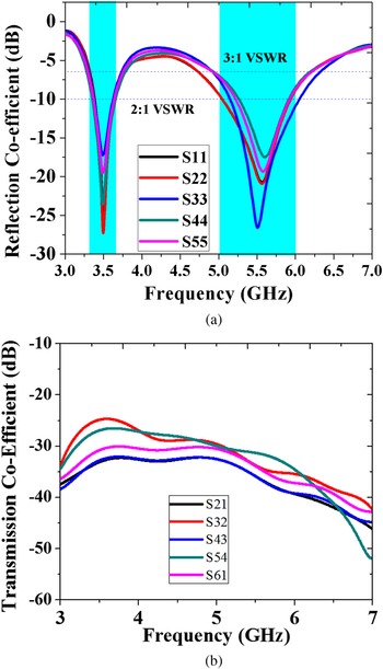
The simulated S-parameters such as reflection coefficients and transmission coefficients of the proposed 10 antenna array are shown in Figs 3(a) and 3(b). As the proposed antenna is vertically symmetric, the results of antenna elements 1–5 are alone depicted. As shown in Fig. 3(a), all the antenna elements are excited by two resonant modes, approximately at 3.4–3.6 and 5–6 GHz with −10 dB bandwidth. Figure 3(b) shows the transmission co-efficient across the two bands, and they are better than 28 dB between any pair of adjacent elements. The results are significantly adequate for the 5G MIMO antenna design. It is noteworthy that, though the separation between the antenna elements 1 & 2 and 3 & 4 is small, the isolation is still better than 28 dB.
Simulated (a) reflection co-efficient, simulated (b) transmission co-efficient.

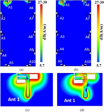
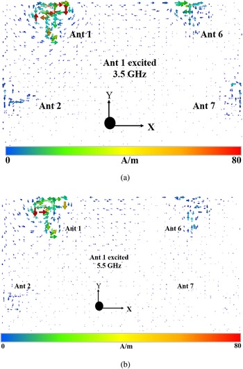
The operation of seven-shaped antenna is described with the help of surface current distribution when antenna 1 is excited at 3.5 and 5.5 GHz, as shown in Figs 4(a)–4(d). One can see that, when antenna 1 is excited at both 3.5 and 5.5 GHz, its corresponding surface current on the ground plane does not spread toward its adjacent antenna port, demonstrating that the coupling effect is very weak, as shown in Figs 4(a) and 4(b).
Simulated overall surface current distribution, when Ant 1 is excited at (a) 3.5 GHz, (b) 5.5 GHz, enlarged view of Ant 1 when excited at (c) 3.5 GHz, (d) 5.5 GHz.

Moreover, it is observed that the surface current density around the antenna is relatively localized. Outside the excited antenna, the magnitude of the current drops rapidly, which reduces the electromagnetic interference with adjacent radiating elements. When antenna 1 is excited for lower band (3.4–3.6 GHz), the current distribution around the closed end of the longer slot is maximum, as shown in Fig. 4(c), and for high band (5–6 GHz), the closed end of the shorter slot is maximum as shown in Fig. 4(d). For both resonating modes, the current at the open end is zero because, for an open slot antenna, the impedance will be maximum at the opening section and minimum at the closed end.
This infers that the electric field at both 3.5 and 5.5 GHz is maximum at the two open ends of the seven-shaped slots, as shown in Figs 5(a) and 5(b). It proves that one-quarter wavelength mode (λ/4) is the fundamental mode for the open end of the seven-shaped slots.
Simulated electric field distribution when Ant 1 is excited at (a) 3.5 GHz, (b) 5.5 GHz.

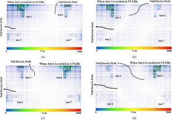
The simulated vector electric field distributions along the ground plane, when antenna 1 and 6 are excited, are shown in Figs 6(a)–6(d). When antennas 1 and 6 are excited separately (at 3.5 and 5.5 GHz), the coupling electric field between antennas 1 & 2 and 6 & 7 is weak (the null field is observed), as illustrated in Figs 6(a)–6(d). It is because antennas 1 & 2 and 6 & 7 are disposed orthogonal to each other and exhibit orthogonal polarization (or polarization diversity).
Simulated vector electric field distributions when Ant 1 is excited at (a) 3.5 GHz, (b) 5.5 GHz, when Ant 6 is excited at (c) 3.5 GHz, (d) 5.5 GHz.

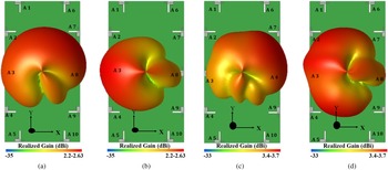
The polarization diversity is explained with the help of a simulated three-dimensional radiation pattern, as shown in Figs 7(a)–7(d). As shown in Figs 7(a) and 7(c), the maximum radiation takes place in +y direction for both the bands, when antenna 1 (horizontal antenna) is excited. On the other hand, when antenna 2 (vertical antenna) is excited for both the bands, the intense radiation is along the –x direction as depicted in Figs 7(b) and 7(d). Thus, the polarization diversity is achieved by disposing the antennas orthogonal to each other, thereby enhancing the isolation.
Simulated three-dimensional radiation pattern when Ant 1 is excited at (a) 3.5 GHz, (b) 5.5 GHz, when Ant 2 is excited at (c) 3.5 GHz, (d) 5.5 GHz.

The vector current distributions of antenna 1 at 3.5 and 5.5 GHz are shown in Figs 8(a) and 8(b). It is observed that the maximum current flows along the edges of the slot antenna toward the +x direction for both the bands and it does not influence its adjacent antennas (2 and 6). Hence, it is quite apparent why the simulated isolation between the adjacent elements is better than 28 dB.
Simulated vector current distribution when Ant 1 is excited at (a) 3.5 GHz, (b) 5.5 GHz.

Parametric study
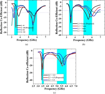
Some parametric studies have been illustrated in Figs 9(a)–9(c) to provide design guidelines for the proposed MIMO antenna array. When the lengths of the two slots (L and L1) are increased, the frequency of resonance for both the bands is shifted toward the lower frequency and vice-versa. Slot radiator lengths L and L1 are completely controlling two frequency bands. As shown in Figs 9(a) and 9(b), the impacts of varying slot lengths are analyzed. When tuning one length parameter, another parameter is kept constant. The results suggest that an increase in the lengths L and L1 will allow the low-band and high-band resonances to shift to the lower frequency and vice-versa. This is reasonable, as the low and high resonant modes are controlled by the longer and shorter open slots, respectively. The low and high-frequency bands are changed according to the lengths L and L1, respectively. Moreover, altering the length of L1 will not affect the lower band. Similarly, changes in the length L do not produce any effect on the high-frequency band. This result demonstrates that the frequency ratio of the two bands can be tuned (by changing L and L1) according to the desired operating frequencies. The variations in the length of the feeding strip (L2) mainly affect the impedance matching as well as shifting in the resonance of both the bands, as shown in Fig. 9(c).
Simulated reflection co-efficient of Ant1 for various values of (a) L, (b) L1, (c) L2.

Measured results and discussions
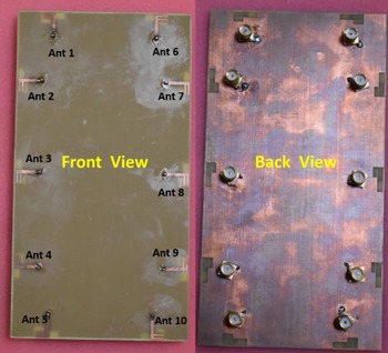
The proposed 10-port MIMO antenna array prototype is fabricated, as shown in Fig. 10, and tested. To carry out the measurements, 50 Ω Sub-Miniature-Version A (SMA) female connectors are soldered at the feeding strips of the antenna elements. The antenna parameters such as S-parameters, isolation, and radiation pattern are measured by terminating all antenna elements to 50 Ω matched loads when the antenna under the test is excited.
Images of fabricated proposed MIMO antenna.

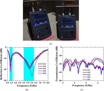
The measured reflection coefficient and isolation levels of the proposed antenna are shown in Figs 11(a)–11(c). The S-parameters are measured using Keysight's Firefox Network Analyzer N9917A. As shown in Fig. 11(b), the reflection coefficient of the antenna elements 1 to 5 well agreed with the simulated results. Each antenna has an impedance bandwidth (2:1 VSWR) of 200 MHz and 1 GHz at 3.5 and 5.5 GHz, respectively. Similarly, the isolation levels (Ant 1 to Ant 5) of adjacent antenna elements are shown in Fig. 11(c). For brevity, the isolation of other antennas has not been shown here. It is observed that all the antenna's isolation levels are better than 28 dB and well correlated with the simulated results.
(a) Measurement setup for S-parameters, (b) measured reflection co-efficient from Antenna 1 to 5, (c) measured transmission co-efficient.

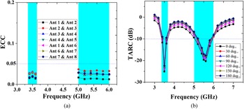
To specify the coupling effects and diversity performance of the MIMO antenna systems, it is necessary to compute the MIMO parameters such as ECC and TARC from the measured far-field radiation pattern and S-parameters, respectively. The ECC and TARC for the proposed antenna are calculated from equations (1) and (3).
The ECC is an important parameter of a MIMO antenna system that can quantify the system's performance. The ECC of any two antennas can be calculated from the measured radiation pattern using equations (1) and (2) [Reference Sun, Feng and Li31].

where

As shown in Fig. 12(a), the measured ECCs of all the antenna pairs are <0.035, which is lower than the acceptable criterion of ECC <0.5. Low values of ECC will result in a higher diversity gain, which shows that the proposed 10-port antenna array possesses better diversity capability.
Measured (a) ECC, (b) TARC.

To further validate the performance and effective bandwidth of the MIMO antenna array, TARC are computed from the measured S-parameters using equation (3).

The TARC curve is plotted for different excitation phases of other ports (with the same amplitude) with respect to port 1 as shown in Fig. 12(b). The proposed MIMO antenna is able to cover the desired frequency spectrum with −10 dB bandwidth while changing the excitation phases. This proves that the proposed design is highly suitable for 5G MIMO smartphone applications.
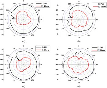
Figures 13(a)–13(d) show the measured radiation patterns of antenna elements 1 and 2 in the xy plane at 3.5 and 5.5 GHz, respectively. The patterns of other antenna components are not shown since the proposed antenna has a symmetrical arrangement. Both antennas have an omnidirectional radiation pattern over the operating bandwidth, as seen in Figs 13(a)–13(d). The maximum radiation (E-phi) for antenna 1 (horizontal antenna) resides at 90° and 30° at 3.5 and 5.5 GHz, respectively, as seen in Figs 13(a) and 13(b). In contrast, antenna 2 (vertical antenna), as seen in Figs 13(c)–13(d), exhibits maximum radiation at 180° and 240° for low band and high band, respectively. The maximum radiation of both horizontal antennas (Ant 1, 5, 6, and 10) and vertical antennas (Ant 2, 3, 4, 7, 8, and 9) is clearly complementary, demonstrating a significant pattern diversity feature.
Measured 2D radiation pattern of antenna 1 at (a) 3.5 GHz, (b) 5.5 GHz, antenna 2 at (c) 3.5 GHz, (d) 5.5 GHz.

Figure 14(a) shows the measured individual radiation efficiency of each element. The antenna efficiency is 63–80% for the low band (3.4–3.6 GHz) and 80–85% for the high band (5–6 GHz). Despite the small distance between the horizontal and vertical antennas (high coupling loss), the efficiency is >63%, ensuring that the proposed antenna has minimum channel capacity loss. The gain of the proposed 10-port MIMO antenna array, as seen in Fig. 14(b), varies from 3 to 3.8 dBi over the desired operating bandwidth, which is substantially higher for mobile phone applications.
(a) efficiency and (b) gain.

MIMO performance
Channel capacity
From the radiation efficiency of the antenna element, the maximum channel capacity of the proposed 10-port antenna array is computed using equation (4), and it is about 46–48.5 bps/Hz for the low band and 51.7 bps/Hz for the high band at 20 dB SNR.

where I is the identity matrix, SNR is the average signal to noise ratio for the mobile terminal, ηT is the number of transmitting antennas, H is the Hermitian matrix, and HT is the Hermitian transpose. The maximum ergodic channel capacities for an ideal MIMO system (antenna elements uncorrelated with each other and provide 100% efficiency) are 57.5 and 11.5 bps/Hz for 10 × 10 and 2 × 2 MIMO systems, respectively. Thus, the proposed 10-port MIMO antenna system provides a channel capacity 4.2 times higher than the ideal 2 × 2 MIMO system as shown in Fig. 15.
Calculated peak channel capacity of the proposed antenna.

User hand effects
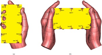
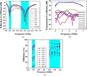
It is well understood that the antenna's performance will be affected when it is in proximity to the human hand. Hence, users' hand effects are investigated by including hand phantom in the simulation. There are two modes of hand operation used here to evaluate the performance; namely, single hand operation (SHO) and two hand operation (THO), as shown in Figs 16(a) and 16(b). Figures 17(a)–17(c) show the simulated S-parameters and the efficiency of the SHO. As antennas 2 and 3 are closer to the index and middle fingers, their reflection co-efficients are completely out of the band. Meanwhile, as the thumb finger is kept on antenna 7, its resonant frequency at the low band is shifted toward the right, as shown in Fig. 17(a). But the performance of all other antennas is almost unchanged in both the low and high bands. The isolation between the antenna elements during SHO is shown in Fig. 17(b). To have more accuracy, isolation between the adjacent antenna elements has been taken, and it is observed that isolation levels are better than 14 dB in both bands. The efficiency of the MIMO antenna during SHO is shown in Fig. 17(c). Because antennas 2, 3, and 7 are so close to the user's hand, their efficiencies have been dropped below 50%. In particular, the efficiency of antenna 7 was drastically reduced below 10% in the low band. As for the remaining antennas, their radiation efficiencies are reduced and varied from 50 to 75% because they are still closer to the human hand phantom.
(a) Single-hand operation (SHO), (b) two-hand operation (THO).

Simulated performance of SHO, (a) reflection co-efficient, (b) transmission co-efficient, (c) efficiency.

Likewise, the simulated reflection co-efficient, isolation, and the efficiencies of THO are shown in Figs 18(a)–18(c), respectively. Antennas 1, 5, 6, and 10 are in close proximity to the user's hand in this scenario. Hence, their reflection co-efficients are slightly shifted from the desired band (low band). Whereas the isolation between the adjacent elements is better than 14 dB. As shown in Fig. 18(c), efficiencies of antenna elements 1, 5, 6, and 10 are considerably reduced below 40%, and for the remaining antennas, the efficiencies are above 50%. The reason for the degradation mentioned above is that the human hands can absorb the radiating power from the antenna and attenuate it. On the whole, the proposed 10 antenna array is highly suitable for 5G mobile phone (3.4–3.6 and 5–6 GHz) applications.
Simulated performance of THO, (a) reflection co-efficient, (b) transmission co-efficient, (c) efficiency.

Impacts of battery
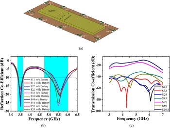
Figure 19(a) shows the simulated model of the proposed antenna along with the battery. In this study, the rectangular metal block of size 118 mm × 40 mm × 4 mm is considered as a battery [Reference Li, Sim, Luo and Yang44], and it is positioned on the front side of the substrate. The battery is electrically connected to the system ground plane via 16 shorting pins. As shown in Figs 19(b) and 19(c), the battery has a negligible influence on the antenna parameters such as reflection coefficient (>−10 dB) and the isolation (>18 dB).
Simulated (a) model of proposed antenna with battery, (b) reflection co-efficient with and without battery, (c) transmission co-efficient with battery.

Effects of LCD panel
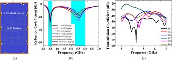
The impact of panel display has also been investigated, as shown in Fig. 20(a). The LCD module comprises two parts: the LCD shield (metal) and the LCD panel. The LCD panel is modeled with the relative permittivity and loss tangent of 7 and 0.02, respectively [Reference Li, Sim, Luo and Yang44]. The LCD module is disposed at a 2 mm distance from the ground plane. The LCD shield is connected to the ground plane; hence, it has proximity to the slot radiators. Due to this proximity to the radiators, there is a slight variation in both the reflection co-efficients and the isolation. But still, the MIMO array is able to achieve the reflection co-efficient >−10 dB and isolation >20 dB as shown in Figs 20(b)–20(c). The results show the MIMO array can exhibit desirable performance in the real-time environment.
Simulated (a) proposed antenna with LCD panel, (b) reflection co-efficient, (c) transmission co-efficient.

Specific absorption rate
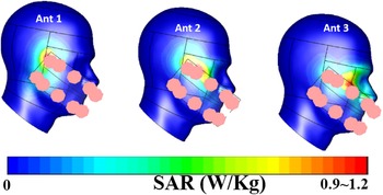
SAR is a significant parameter to be taken into account while designing a mobile phone antenna, because it estimates the amount of electromagnetic power absorbed by the human body. The head phantom is modeled for the proposed antenna, and SAR of antenna 1, 2, and 3 are observed. From Fig. 21, one can see that the maximum values of SAR are within 1.2 W/kg at 1 g of tissue. The SAR of the mobile phone antenna will be varied with respect to the distance between the mobile phone and the human head. The distance has been altered from 5 to 10 mm, and corresponding SAR has been estimated for our design. It is observed that the closer the distance between the antenna and the head phantom, the higher the value of SAR and vice versa.
SAR analysis of Ant 1−3 at 1(W/kg).

Table 1 shows the performance comparison of the proposed MIMO antenna array with some other MIMO antenna arrays reported for 5G mobile handsets. It is apparent that the proposed antenna has very good isolation >28 dB, ECC <0.035, TARC >10 dB along with good radiation and MIMO performance.
Performance comparison of the proposed work with previously published works

a Only 5G antennas are considered; LB, lower band; HB, higher band.
Effects of metal frame
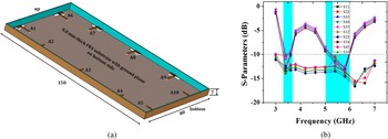
The metal frame of height 7 mm is added along the four side edges of the proposed MIMO antenna, as shown in Fig. 22(a) and simulated. The metal frame is printed on the 0.8 mm-thick FR4 substrate. However, the antenna with a metal frame can resonate in the two bands (3.5 and 5.5 GHz) as shown in Fig. 22(b). The simulated reflection co-efficients are very low compared with the non-metal frame environment, and transmission co-efficients are better than 12.5 dB only. The reason for the above loss in antenna's performance is that, according to electromagnetic image theory, when an antenna is located parallel to a conductor (metal frame), the radiation properties are seriously harmed by the out-of-phase electric current [Reference Balanis46]. Therefore, the proposed antenna is highly suitable for non-metal frame mobile phone applications.
(a) Proposed antenna with metal frame, (b) S-parameters.

Conclusion
A 10-port MIMO antenna system for 5G mobile phones operating at 3.4–3.6 and 5–6 GHz has been successfully investigated. The high isolation (>28 dB) among the adjacent antenna elements is achieved by placing the antenna elements orthogonally. Therefore, MIMO parameters such as ECC (<0.035) and TARC (>10 dB) are achieved better than their margin levels. The measured efficiency and gain of the proposed antenna range from 63 to 85% and 3 to 3.8 dBi, respectively. The calculated peak channel capacity in the 10 × 10 MIMO arrangement is achieved up to 48.5 bps/Hz for the low band and 51.7 bps/Hz for the higher band at 20 dB SNR. The proposed antenna has also shown better performance with the user's hand and SAR. Therefore, the 10-port antenna reported in this work could be a promising candidate for future mobile applications.
Acknowledgements
The authors wish to thank RF Centre of Excellence SASTRA-Keysight at SASTRA for their technical support in fabrication and measuring the antenna parameters
 D. Rajesh Kumar was born in Madurai, Tamilnadu, India in 1987. He obtained B.E. in electronics and communication engineering from Anna University, Tamilnadu, India in 2008 and M.E. in communication systems from Anna University, Tamilnadu, India in 2013. He has 9 years of teaching experience as assistant professor in SACSMAVMM Engineering College, Madurai, India. Currently, he is working as a research assistant and pursuing Ph.D. in the field of antennas for 5G communications in SASTRA Deemed University, Tamilnadu, India. His research areas include mobile phone antenna design and RF system design.
 G. Venkat Babu is assistant professor in the Department of Electronics and Communication, SEEE, SASTRA Deemed University, Tamilnadu, India. He obtained B.E. in electronics and communication from Bharathidasan University, Trichy, M.E. in microwave communication and radar from Dr. B.R. Ambedkar University, Agra, India and Ph.D. in electronics and communication from Bhagwant University, Ajmer, India. His research is related to reconfigurable antenna and RF-MEMS. He has academic and research experience of about 19 years. He has published his research work in reputed journals, international and national conferences. He co-authored a book in the area of electromagnetic fields. He is a member of IEEE (Society APS & MTS), life member. of IETE and ISTE.
 K.G. Sujanth Narayan was born in Chennai, Tamilnadu, India, in 1996. He obtained B.E. in electronics and communication engineering from R.M.K. Engineering College, Kavarapettai, Tamilnadu and M.Tech. in communication systems from SASTRA Deemed University, Thanjavur, Tamilnadu in the years 2017 and 2019, respectively. Currently, he is working as a research assistant and pursuing Ph.D. in the area of antennas and RF system design from School of Electrical and Electronics Engineering, SASTRA Deemed University, Thanjavur, Tamilnadu. He is a member of IEEE. His research areas include antennas, electromagnetics, RF system design, EMI/EMC and vehicular communication.
 N. Raju obtained M.E. in applied electronics from Anna University, and Ph.D. in speech processing from SASTRA Deemed to be University, India. His main research interests are robotics, embedded systems, VLSI design, speech processing, and machine learning. He has published more than 30 research papers in reputed international journals and conferences. He is currently working as senior assistant professor in the Department of ECE, School of EEE, SASTRA Deemed University, Thanjavur. He is a life member of the Indian Society of Systems for Science and Engineering (ISSE).