1. Introduction
Neurological injuries, such as stroke, spinal cord injury, and skeletal muscle weakness in the elderly, may largely limit the ability of this population to achieve major activities of daily living [1]. Recently, there has been a growing interest in developing exoskeleton devices, which can help the disabled with motor assistance and rehabilitation training [2, Reference T. Bosch3]. An exoskeleton robot is usually defined as designed following the shape and function of the body. Exoskeleton robots can effectively integrate the cognitive abilities of humans and the advantages of robotic devices to help users accomplish rehabilitation activities [4].
In recent years, many studies have been conducted to improve the performance of lower extremity exoskeletons [Reference Mokhtari, Taghizadeh and Mazare5–Reference Zhang and Zhang7]. As precision and portable exoskeleton designs have evolved, researchers have also focused on improving control strategies to increase exoskeletons’ precision, efficiency, and comfort. Since humans wear the exoskeleton, good interaction between the exoskeleton and humans is a key factor, which means the exoskeleton needs to realize compliance control [Reference Ferraresi, Muscolo, De Benedictis, Paterna and Gisolo8]. The lower limb exoskeleton compliance control is mainly divided into two categories, one is passive compliance control and the other is active compliance control. Passive compliance control is to install some cushioning devices (such as springs) on the exoskeleton to absorb or relieve the impact energy between the exoskeleton and humans during the movement [Reference Penzlin9, Reference Cao and Wu10]. Active compliance control means that the robot uses the force feedback information and adopts a certain control strategy to actively control the force [Reference Qian, Ai, Zhou, Liao, Xiao and Guo11]. The Swiss Lokomat lower extremity rehabilitation exoskeleton uses a hybrid force/position adaptive control strategy in active rehabilitation [Reference Lee, Park and Kim12, Reference Li, Yuan, Luo, Su, Zhao, Xu and Pi13]. The hybrid force/position control strategy utilizes dual force and position control to realize compliance rehabilitation training. The ALEX lower limb exoskeleton also employs a hybrid force/position control strategy, allowing this lower limb exoskeleton to achieve desired gait planning while applying less force on the wearer’s leg [Reference Kazerooni14]. However, this method requires a very accurate model of the robot dynamics. And the hybrid force/position control requires real-time detection of force and position changes, so many sensors need to be installed. Impedance control has been widely used to realize compliance control by adjusting the dynamic relationship between the human-machine position and the interacting force [15–Reference Wang18]. The Ekso lower limb exoskeleton used an impedance control strategy based on a force field controller, which firstly sets the desired motion trajectory and then corrects the gait trajectory by detecting the interactive forces between the human and the machine [15]. Chen designed an impedance control strategy with a perturbation observer for the exoskeleton robot system. The experimental results show that the exoskeleton could actively adjust the motion trajectory when encountering obstacles and accurately track human motion trajectory [Reference Chen, Wang, Song, Wang, Zhang and Li16].
In the actual use of the process, the state of the robot and external disturbances are random. Hence, impedance control with fixed impedance parameters cannot adapt to the unstable motion environment. With the development of science and technology, intelligent algorithms are increasingly used to assist impedance control for active control [Reference Mokhtari, Taghizadeh and Mazare19–Reference Qian, Ai, Zhou, Liao, Xiao and Guo25]. Majied proposed a novel hybrid optimized adaptive sliding mode impedance control method for a lower limb exoskeleton robot with seven active joints. The simulation results reveal the superiority of the controller in comparison with SMC [Reference Mokhtari, Taghizadeh and Mazare19]. To improve human-machine coordination, Chen proposed an improved impedance control strategy based on a genetic algorithm to follow the tracking trajectory. Compared with the traditional method, the impedance parameters can be calculated and adjusted online, and the gait trajectory can be well tracked [Reference Chen, Li and Zeng20]. However, this study is still in the simulation test stage, and the effectiveness of the application to the hardware platform needs to be further verified. A time-varying desired impedance model based on the wearer’s lower extremity motility is proposed to provide appropriate power and balance assistance during sit-to-stand movements. The effectiveness of the method was verified through experiments with four healthy subjects. Good results were obtained regarding reasonable power assistance and balance reinforcement [Reference Huo, Moon, Alouane, Bonnet, Huang, Amirat and Mohammed21]. Akdoğan, Erhan designed an adaptive impedance control system for a knee rehabilitation robot using the interaction forces between the knee joint and the robot [Reference Akdoğan, Taçgin and Adli23]. The experimental results showed that real-time adjustment of the target impedance parameters could effectively regulate the active release forces of the knee joint. However, it still has some limitations in complex rehabilitation training behaviors.
Although the conventional impedance control method has achieved some good results, the performance of the whole system still depends on the manual selection of the target impedance control parameters. And the effect of existing compliance control algorithms is not ideal. In this study, a fuzzy radial-based impedance (RBF-FVI) controller is presented to realize compliance control. The main contributions of the paper are:
-
1. A 6 degree of freedom (DOFs) lower limb exoskeleton robot was designed. The hip and knee of each artificial leg can provide two electric-powered DOFs for flexion/extension. And two passive-installed DOFs of the ankle were used to achieve the motion of supination /overpronation and plantarflexion/dorsiflexion. The human-machine coupled dynamics equations based on the spring-damping model are established, and the object under study is determined.
-
2. To meet the rehabilitation training needs of patients based on conforming to the laws of human movement, this paper proposes an RBF-FVI controller, which includes a fuzzy position control module and an outer-loop impedance control module. The fuzzy position control module is mainly used to control the desired training trajectory tracking and the position adjustment amount. The external loop impedance control module can establish the dynamic force/position relationship between the subject and the exoskeleton, enabling the patient to adjust the gait trajectory autonomously in real-time to improve the suppleness of human-machine interaction.
-
3. Simulation experiments are performed on the joint platform of MATLAB/Simulink and ADAMS. The performance is also analyzed in comparison with the conventional control algorithm. The hardware tests of the exoskeleton robot system were conducted. The test results show that the robot system’s safety control and impedance control can be achieved, and the operator and the exoskeleton robot can realize cooperative movement.
The rest of the paper is organized as follows: Section 2 describes exoskeleton robot system. Section 3 illustrates the design of RBF-FVI controller. The simulation experiment and analysis are presented in Section 4. Section 5 describes human-machine coupling test. Finally, the conclusion of this work is given in Section 6.
2. Exoskeleton robot system
2.1. Structure of exoskeleton robot
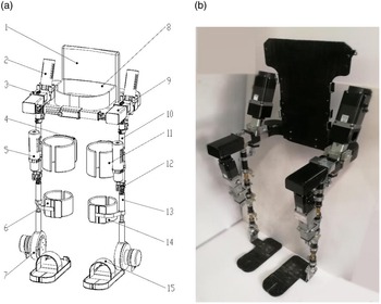
The developed lower limb exoskeleton is shown in Fig. 1. The exoskeleton robot designed in this paper mainly considers the motion in the sagittal plane. For each leg, it has one active DoF for the hip joint and knee joint, respectively, and one passive DoF for the ankle joint.
(a) Overall structure diagram (1) Back support; (2) Driving source of hip joint; (3) Hip joint component; (4) Brace of thigh; (5) Driving source of knee joint; (6) Brace of calf; (7) Ankle joint component; (8) Flexible belt of waist; (9) Waist component; (10) Thigh component; (11) Flexible belt of thigh; (12) Knee joint component; (13) Calf component; (14) Flexible belt of calf; (15) Pedal; (b). Exoskeleton mechanical diagram.

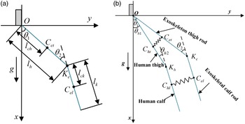
Each leg will alternate into the support phase and the swing phase. The lower limb exoskeleton control system mainly considers the following ability of the human lower limb motion and the magnitude of the interaction force during the motion. Therefore, in this paper, the dynamics of the swing phase are modeled. The single leg of the lower limb exoskeleton is simplified to a duplex structure consisting of the hip and knee joints as well as the thigh and calf rods. A simplified model of the swing phase of the lower limb exoskeleton was established, as shown in Fig. 2(a). The hip joint is taken as the origin of the coordinate system. The point O is the hip joint of the exoskeleton, K e is the knee joint of the exoskeleton, C et is center of mass of the thigh rod, C el is the center of mass of the calf rod, the mass of the thigh rod is m eh , the mass of the calf rod is m ek , the length of the thigh rod is l h , the length of the calf rod is l k , the distance from the C et to the point O is l ch , the distance from the C el to the knee joint is l ck , the rotational inertia of the thigh rod is I eh , the rotational inertia of the calf rod is I ek . The angle between the thigh rod and the vertical direction is θ 1 . The angle between the calf bar and the thigh bar is θ 2 . The counterclockwise direction is specified as the positive direction.
(a) Simplified model of lower extremity exoskeleton in swing phase; (b )Human-machine coupling system model.

The exoskeleton robot dynamics equation is:
 \begin{equation} \tau =M\!\left(\theta \right)\ddot{\theta }+C\!\left(\theta, \dot{\theta }\right)\dot{\theta }+G\!\left(\theta \right) \end{equation}
where
 $\theta, \dot{\theta }, \ddot{\theta }$
are 2 × 1 order lower limb exoskeleton joint angle, velocity and acceleration, respectively;
 $M\!\left(\theta \right)$
is 2 × 2 order inertia matrix;
 $C\!\left(\theta, \dot{\theta }\right)$
is 2 × 2 order Coriolis force matrix;
 $G\!\left(\theta \right)$
is 2 × 1 order gravity matrix;
 $\tau$
is 2 × 1 order joint driving force matrix. The joint torque can be obtained from the torque sensor.
The joint torque is:
 \begin{equation} \tau =\left[\begin{array}{l} \tau _{1}\\[5pt] \tau _{2} \end{array}\right] \end{equation}
where τ 1 and τ 2 are the torque of hip joint and knee joint, respectively.
According to Lagrange dynamic equation, the calculation of the generalized torque of the hip joint and knee joint are:
 \begin{align} \tau _{1}&=\frac{d}{dt}\frac{\partial L}{\partial \dot{\theta }_{1}}-\frac{\partial L}{\partial \theta _{1}}=m_{eh}l_{ch}^{2}\ddot{\theta }_{1}+l_{h}\ddot{\theta }_{1}+m_{k}l_{h}^{2}\ddot{\theta }_{1}+m_{k}l_{ck}^{2}\ddot{\theta }_{1}+I_{ek}\!\left(\ddot{\theta }_{1}+\ddot{\theta }_{2}\right) \nonumber \\[5pt] & \quad +m_{ek}l_{ck}^{2}\ddot{\theta }\enspace +2m_{k}l_{h}l_{ck}\!\left(\ddot{\theta }_{1}\cos\!\theta _{2}-\dot{\theta }_{1}\dot{\theta }_{2}\sin\!\theta _{2}\right) +m_{ek}l_{h}l_{ck}\left(\ddot{\theta }_{2}\cos\!\theta _{2}-\dot{\theta }_{2}^{2}\sin\!\theta _{2}\right)+m_{eh}gl_{ch}\sin\!\theta _{1} \nonumber\\[5pt] & \quad +m_{ek}g\!\left(l_{h}\sin\!\theta _{1}+l_{ck}\sin\!\left(\theta _{1}+\theta _{2}\right)\right) \end{align}
 \begin{align} \tau _{2}&=\frac{d}{dt}\frac{\partial L}{\partial \dot{\theta }_{2}}-\frac{\partial L}{\partial \theta _{2}}=\left(m_{ek}l_{ck}^{2}+I_{ek}\right)\!\left(\ddot{\theta }_{1}+\ddot{\theta }_{2}\right)+m_{ek}l_{h}l_{ck}\!\left(\ddot{\theta }_{1}\cos\!\theta _{2}-\dot{\theta }_{1}\dot{\theta }_{2}\sin\!\theta _{2}\right)\nonumber \\[5pt] & \quad +m_{ek}l_{h}l_{ck}\dot{\theta }_{1}\!\left(\dot{\theta }_{1}+\dot{\theta }_{2}\right)\sin\!\theta _{2} +m_{ek}gl_{ck}\sin\!\left(\theta _{1}+\theta _{2}\right) \end{align}
The design of the power system adopts the linear actuator of servo motor and ball screw, and its motion mode is similar to human lower limb skeletal muscle. The relationship between output torque of servo motor and thrust of the ball screw is:
 \begin{equation} \tau _{m}=\frac{F\times L}{2\times \pi \times \eta } \end{equation}
where τ
m
is output torque of servo motor, F is thrust force of ball screw, L is the telescopic length of the ball screw,
 $\eta$
is transmission efficiency from motor to ball screw.
2.2. Human-machine interaction torque
The human lower limb and the exoskeleton are bundled together, and there is always an interaction torque between the two during the moving process. The human-machine coupled system model in the swing phase is shown in Fig. 2(b). It is assumed that the thigh and calf rods of the exoskeleton are the same length as the human thigh and calf, respectively, and the center of mass is also in the same position. K h is the human knee joint, C ht and C hl are the center of mass human thigh and human calf, respectively. The mass of human thigh is m hh , the mass of human calf is m hk .
 \begin{equation} \tau _{dis}=\left[\begin{array}{l} \tau _{dis1}\\[5pt] \tau _{dis2} \end{array}\right] \end{equation}
 \begin{equation} \tau _{dis1}=K_{imp}\!\left(\theta _{h1}-\theta _{1}\right) \end{equation}
 \begin{equation} \tau _{dis2}=K_{imp}\!\left(\theta _{h2}-\theta _{2}\right) \end{equation}
where τ dis1 and τ dis2 are human-machine interaction torque of hip joint and knee joint, respectively. K imp is the elasticity coefficient between the human and the exoskeleton, and K imp = 17 N·m/rad. θ h1 and θ h2 are the rotation angle of human hip joint and knee joint, respectively.
3. Fuzzy radial-based impedance controller design
3.1. Overall structure
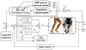
In the whole rehabilitation training process, to meet the patient’s rehabilitation needs based on human movement patterns, this paper proposes an RBF-FVI control algorithm. The proposed control strategy mainly consists of an inner-loop fuzzy position control module and an outer-loop impedance control module, as shown in Fig. 3.
Overview chart of RBF-FVI controller.

3.2. Inner-loop fuzzy PID position control module
The fuzzy position control module is mainly used to realize the tracking control of the desired training trajectory and position adjustment. e(t) and u(t) represent the input and output of the PID controller, respectively.
 $\Delta \theta, \Delta \dot{\theta }$
are the input variables of the fuzzy control rules. Δτ is the force error. τ
m
is the output torque. K
p
, K
i,
and K
d
are the proportional, integral and differential gains. θ
e
and θ
d
are the actual and desired positions of the end of the exoskeleton, respectively. τ
d
are the desired torque. B(t), K(t), and M(t) denote the amount of damping parameter, stiffness parameter, and inertia parameter, respectively.
Conventional PID controller was able to dynamically adjust the relationship between force and position. But it is still difficult to satisfy complex nonlinear and strongly coupled systems, such as exoskeleton robots. However, fuzzy PID control does not require an accurate mathematical model. The fuzzy mathematical theory and methods can be used to adjust the PID parameters in real-time to achieve optimal control [Reference Baigzadehnoe, Rahmani, Khosravi and Rezaie26, Reference Stojcsics27]. In order to realize the parameter adaptive control, the input is the position error
 $\Delta \theta$
and the change rate of position error
 $\Delta \dot{\theta }$
, and the output is the real-time adjusted parameters K
p
, K
i
, and K
d
. When the joint angle increases, it is set to a positive value, and when it decreases, it is set to a negative value. The fuzzy rule of K
p
is used for illustration. The learning rate adjustment principle of K
p
is summarized as follows: In the PID controller, the selection of K
p
value is determined by the system’s response speed. Increasing K
p
can improve the response speed and reduce the steady-state deviation; however, too large a K
p
value will produce a large overshoot and make the system unstable. Therefore, a larger K
p
value should be taken at the beginning of regulation to improve the response speed, while in the middle of regulation, K
p
is taken as a smaller value to make the system have a smaller overshoot and ensure a certain response speed; while in the late regulation process, K
p
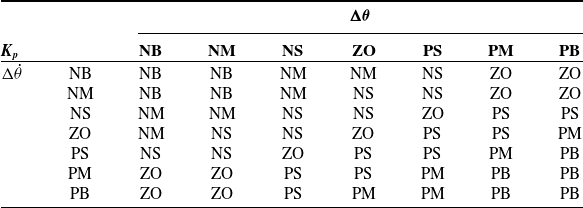
is adjusted to a larger value to reduce the static difference and improve the control accuracy. The fuzzy sets of both input and output variables are set to seven groups, which are NB (negative large), NM (negative medium), NS (negative small), ZO (zero), PS (positive small), PM (positive medium), and PB (positive large). This sets an extremely large number of levels, and the rules are formulated flexibly and carefully to adapt to control under different conditions. The setting fuzzy control rules are shown in Table I.
The fuzzy control rules for K p.

3.3. Outer-loop neural network regulation impedance parameter module
The outer-loop impedance control was used to regulate the impedance parameters and compensate for uncertainty. The adjustment amount of the movement trajectory was obtained through the human-machine interaction force so that the movement of the rehabilitation robot can actively adapt to the movement intention of the patient and realize the active compliance of the movement function rehabilitation training. The human-machine interaction force can be calculated by solving the difference between the measured value of the torque sensor installed at the robot joint and the value calculated by the dynamic model of the human-machine coupling system. Through inverse kinematics, the reference trajectory in Cartesian space can be converted into a reference trajectory in joint space. Then, the corrected reference trajectory can be used as a reference trajectory, reflecting the patient’s active motion intention.
3.3.1. Impedance control
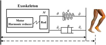
Instead of directly controlling the magnitude of the force between exoskeleton robot and human, impedance controller controls the robot system by establishing the relationship between the force and position error. There have been many studies using impedance control methods to control exoskeleton robots for multiple motion tasks [Reference Li, Li, Li, Su, Kan and He28, Reference Yu, Li, He, Feng, Cheng and Silvestre29]. A second-order differential equation is usually used to represent the impedance model of the exoskeleton robot, which can be expressed as a mass-spring-damping system, as shown in Fig. 4.
Impedance control model.

The target impedance is
 \begin{equation} \tau =M\!\left(\ddot{\theta }_{d}-\ddot{\theta }\right)+B\!\left(\dot{\theta }_{d}-\dot{\theta }\right)+K\!\left(\theta _{d}-\theta \right) \end{equation}
where τ is the interaction torque between human and exoskeleton robot, M is the impedance inertia matrix, B is the impedance damping matrix, K is the impedance stiffness matrix.
 $\theta _{d}, \dot{\theta }_{d}, \ddot{\theta }_{d}$
are the position, velocity, and acceleration of human in Cartesian space.
 $\theta, \dot{\theta }, \ddot{\theta }$
are the position, velocity, and acceleration of exoskeleton robot in Cartesian space.
Impedance control successfully accommodates position control and force control into a dynamic framework that allows position and force to satisfy desired dynamic relationship [Reference Brahmi, Driscoll, El Bojairami, Saad and Brahmi30]. There are two main types of impedance control, namely force-based impedance control and position-based impedance control. Compared with force-based impedance control, the position-based impedance control does not need to establish a very accurate dynamics model, and the position-based impedance control theory is more mature and superior in terms of stability and accuracy. Therefore, this paper adopts position-based impedance control to optimize the design of the exoskeleton robot torque feedback control system. Position-based impedance control obtains the position to be compensated by calculating the human-machine contact force deviation. The compensation force is converted to joint compensation angle.
For single joint, when there is a deviation between the actual position of the joint and the operator’s position, the actual contact force is calculated by the position deviation and contact stiffness. The desired position of the exoskeleton joint is:
 \begin{equation} {\widetilde{{\theta }}}_{d}=\theta _{d}-\theta _{ref} \end{equation}
where θ d is desired human joint angle. θ ref is impedance compensation angle.
Let
 $\theta _{e}=\widetilde{{{\theta }}}_{d}-\theta$
, the position control is calculated as:
 \begin{equation} \tau -\tau _{pd}=\hat{M}\!\left(\theta _{d}\right)\ddot{{\widetilde{{\theta }}}}_{d}+\hat{C}\!\left({\widetilde{{\theta }}}_{d}, \dot{{\widetilde{{\theta }}}}_{d}\right)\dot{{\widetilde{{\theta }}}}_{d}+\hat{G}\!\left({\widetilde{{\theta }}}_{d}\right) \end{equation}
 \begin{equation} \tau _{pd}=K_{p}\theta _{e}+K_{d}\frac{d\theta _{e}}{dt} \end{equation}
where θ is actual exoskeleton joint angle. τ
pd
is compensation torque from PID feedback control.
 $\hat{M}\!\left(\theta \right), \hat{C}\!\left(\theta, \dot{\theta }\right)$
and
 $\hat{G}\!\left(\theta \right)$
are the ideal inertia matrix, damping parameter matrix, and gravity matrix of the exoskeleton robot.
3.3.2. Radial basis function (RBF) neural network
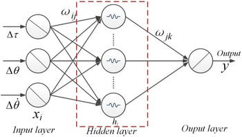
The RBF neural network is a three-layer neural network with an input layer, a hidden layer, and an output layer [Reference Zhang, Zhang and Zhang31]. The transformation between the input layer to the hidden layer is nonlinear. The transformation from the hidden layer to the output layer is linear. The RBF neural network has a fast learning speed and is suitable for real-time control systems. In this study, the RBF neural network model was used to adjust the target impedance parameters in real-time and compensate for the model’s uncertainty. Based on the traditional impedance control, the RBF neural network algorithm is used to adjust the impedance parameters in real time to improve the stability and flexibility of the control algorithm to achieve better control results. The structure of the RBF neural network is shown in Fig. 5.
Structure diagram of RBF neural network.
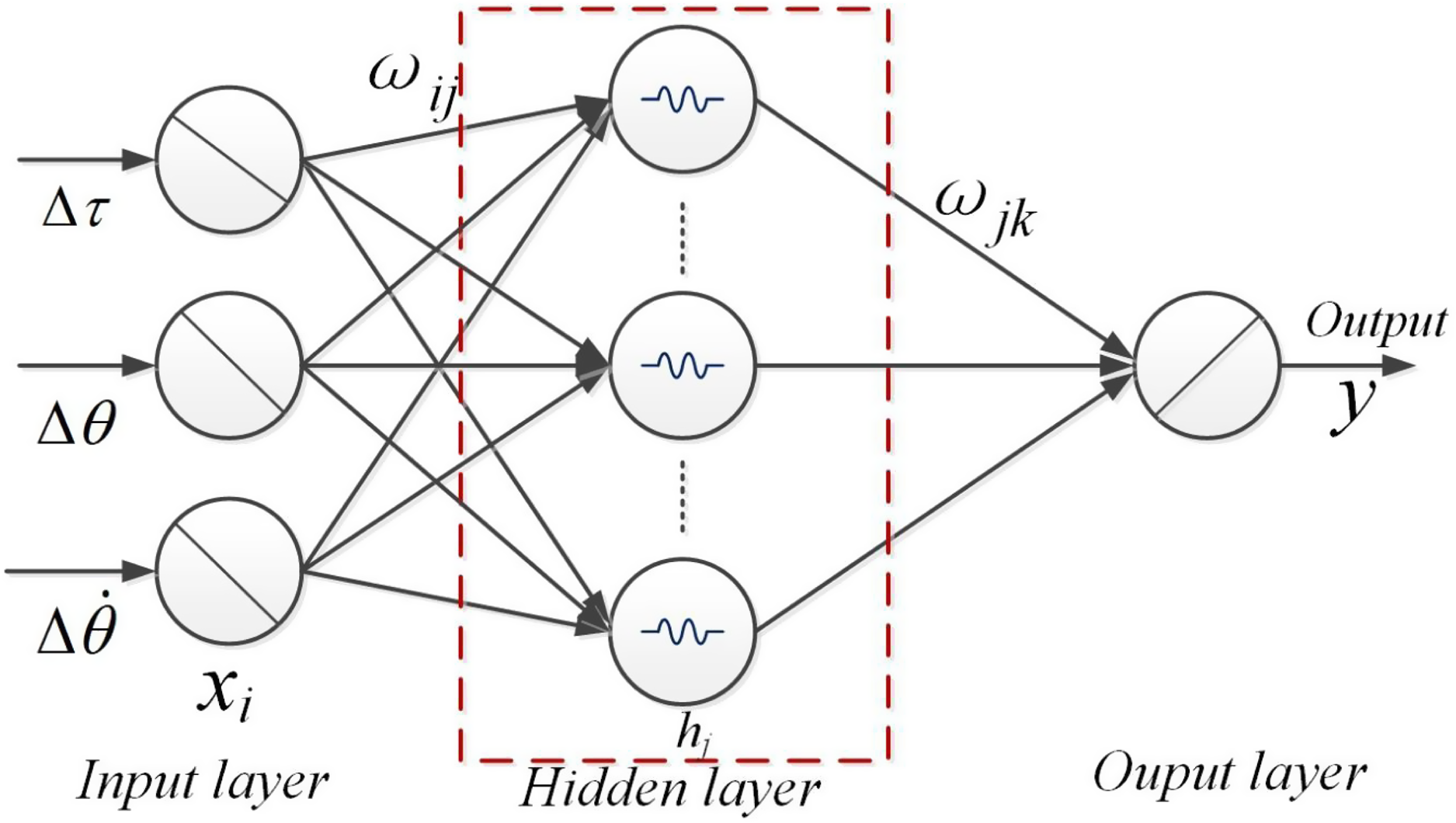
The input layer of the RBF neural network is the vector x
i
. When the inputs are different, the adjusted impedance parameters are also different. When the input is position error
 $\Delta{\theta}$
and force error
 $\Delta{\tau}$
, the output variable is the stiffness correction
 $\Delta$
K. The hidden layer of the RBF neural network is described as:
 \begin{equation} x_{j}=\sum _{i=1}^{m}\sum _{j=1}^{l}\omega _{ij}s_{j}=\sum _{j=1}^{l}\left(\omega _{1j}\Delta \tau +\omega _{2j}\Delta \dot{\theta }\right) \end{equation}
When the input is velocity error
 $\Delta \dot{\theta }$
and force error
 $\Delta{\tau}$
, the output variable is the damping correction
 $\Delta$
B.
 \begin{equation} x_{j}=\sum _{i=1}^{m}\sum _{j=1}^{l}\omega _{ij}s_{j}=\sum _{j=1}^{l}\left(\omega _{1j}\Delta \tau +\omega _{2j}\Delta \dot{\theta }\right) \end{equation}
 \begin{equation} d_{j}=f\!\left(x_{j}\right) \end{equation}
where m denotes the number of input variables; the RBF neural network designed in this paper has two input variables, that is, m = 2. s
j
and d
j
are the input and output of the hidden layer neural network nodes, respectively, and
 $\omega$
ij
is the weighting coefficient between the input layer and the hidden layer.
The activation function of the hidden layer neuron is:
 \begin{equation} f\!\left(x_{j}\right)=\exp\!\left(\!-\!\left\| x_{j}-c_{j}\right\| ^{2}/\left(2b_{j}^{2}\right)\right),j=1,2,\ldots,l \end{equation}
where c j is the center of the basis function. b j is the width of the basis function. l is the number of nodes in the hidden layer.
The output layer of the RBF neural network is described as:
 \begin{equation} y=\omega _{jk}d_{j}+f \end{equation}
 \begin{equation} y_{m}=\omega _{jk}d_{j} \end{equation}
where f is modeling error and external perturbation.y is the output value of the RBF network in the presence of the disturbance term f. y
m
is the output value of the RBF network without f.
 $\omega$
jk
is the weighting coefficient between the hidden layer and the output layer.
The supervised learning method was used to train all parameters of the RBF neural network (center of RBF c
j
, variance b
j,
and weights between the hidden layer to the output layer
 $\omega$
jk
). This is mainly done by performing gradient descent on the cost function and then correcting each parameters. Specifically, firstly, the parameters of RBF neural network are initialized randomly; then, the supervised training optimization is performed by gradient descent for all three parameters in the network. The cost function was set as:
 \begin{equation} E=\frac{1}{2}(y\mathit{-}y_{m})^{2} \end{equation}
Then in each iteration, the parameters are adjusted at a certain learning rate in the negative direction of the error gradient until the best parameter values are obtained.
 \begin{equation} c_{ij}\!\left(t\right)=c_{ij}\!\left(t-1\right)-\eta \frac{\partial E}{\partial c_{ij}\!\left(t-1\right)}+\alpha\!\left[c_{ij}\!\left(t-1\right)-c_{ij}\!\left(t-2\right)\right] \end{equation}
 \begin{equation} b_{ij}\!\left(t\right)=b_{ij}\!\left(t-1\right)-\eta \frac{\partial E}{\partial b_{ij}\!\left(t-1\right)}+\alpha \!\left[b_{ij}\!\left(t-1\right)-b_{ij}\!\left(t-2\right)\right] \end{equation}
 \begin{equation} \omega _{jk}\!\left(t\right)=\omega _{jk}\!\left(t-1\right)-\eta \frac{\partial E}{\partial \omega _{jk}\!\left(t-1\right)}+\alpha \!\left[\omega _{jk}\!\left(t-1\right)-\omega _{jk}\!\left(t-2\right)\right] \end{equation}
where c
ij
(t) is the central component of the i
th
hidden layer neuron for the j
th
input neuron at the t times iteration; b
ij
(t) is the width vector of the neuron corresponding to c
ij
(t);
 $\omega$
jk
(t) is the conditioning weight between the j
th
output neuron and the k
th
hidden layer neuron at the t times iteration of computation.
 $\eta$
is learning rate,
 $\eta$
= 0.8. α is the momentum factor, α = 0.5.
3.4. Stability analysis
The Laypunov function was selected as:
 \begin{equation} V=X^{T}PX+\left\| \widetilde{{{\omega }}}_{jk}\right\| _{F}^{2} \end{equation}
There exists a positive definite matrix P, satisfying
 $A^{T}P+PA=-Q$
.
where Q is a given positive definite symmetric matrix.
 \begin{equation} \widetilde{{{\omega }}}_{jk}={\omega _{jk}}^{*}-\hat{\omega }_{jk} \end{equation}
where
 ${\omega _{jk}}^{*}$
is actual weight of RBF neural network,
 $\hat{\omega }_{jk}$
the estimated value of the weight.
Based on the theory of stability analysis of control systems, it is defined as:
 \begin{equation} \left\| \omega _{jk}\right\| _{\mathrm{F}}^{2}=tr\!\left({\widetilde{{{\omega }}}_{jk}}{}^{T}\widetilde{{{\omega }}}_{jk}\right)\geq 0 \end{equation}
where tr() is the trace of the matrix.
The modeling error and external perturbation f are described as:
 \begin{equation} f=\hat{\omega }_{jk}\varphi \!\left(x_{j}\right) \end{equation}
where
 $\phi$
(x
j
) is the output of the Gaussian basis function, and
 $\varphi (x_{j})=[f(x_{1}),f(x_{2}),\ldots f(x_{j}),\ldots f(x_{l})]$
.
The error state equation of the system is given by
 \begin{equation} \dot{X}=AX+B\left[f-\hat{f}\!\left(x,\omega _{jk}\right)\right] \end{equation}
where
 $X=\left[\begin{array}{l} e \\[5pt] \dot{e} \end{array}\right],A=\left[\begin{array}{l@{\quad}l} 0 & I\\[5pt] K_{p}& K_{d} \end{array}\right],B=\left[\begin{array}{l} 0\\[5pt] I \end{array}\right], \hat{f}$
is the estimated value of f.
The relevant term in Eq. (27) is transformed as:
 \begin{equation} f-\hat{f}\!\left(x,\omega _{jk}\right)=f-\hat{f}\!\left(x,{\omega _{jk}}^{*}\right)+f\!\left(x,{\omega _{jk}}^{*}\right)-\hat{f}\!\left(x,\omega _{jk}\right)=\beta +{\omega _{jk}}^{*T}\varphi \!\left(x_{j}\right)-{\hat{\omega }_{jk}}^{T}\varphi \!\left(x_{j}\right)=\beta +{\hat{\omega }_{jk}}^{T}\varphi \!\left(x_{j}\right) \end{equation}
where
 $\beta$
is the modeling error of the RBF neural network.
 \begin{equation} \dot{X}=AX+B\!\left(\beta +{\hat{\omega }_{jk}}{}^{T}\varphi \!\left(x_{j}\right)\right) \end{equation}
Then,
 \begin{equation} \dot{V}=X^{T}P\dot{X}+\dot{X}^{T}PX+2tr\!\left({\dot{\widetilde{{{\omega }}}}_{jk}}{}^{T}\widetilde{{{\omega }}}_{jk}\right)\enspace =\mathrm{X}^{T}P\!\left[AX+B\!\left(\beta +{\widetilde{{{\omega }}}_{jk}}{}^{T}\varphi \!\left(x_{j}\right)\right)\right]^{T}PX+2tr\!\left({\dot{\widetilde{{{\omega }}}}_{jk}}{}^{T}\widetilde{{{\omega }}}_{jk}\right) \end{equation}
Substitute Eq. (27) into Eq. (30) to obtain
 \begin{equation} \dot{V}=-X^{T}QX+\varphi ^{T}\!\left(x_{j}\right)\widetilde{{{\omega }}}_{jk}B^{T}PX+\beta ^{T}B^{T}PX+2tr\!\left({\dot{\widetilde{{{\omega }}}}_{jk}}^{T}\widetilde{{{\omega }}}_{jk}\right) \end{equation}
The adaptive rate is taken to be
 \begin{equation} \dot{\widetilde{{{\omega }}}}_{jk}=\varphi\!\left(x_{j}\right)X^{T}PB-k_{1}\left\| X\right\| \widetilde{{{\omega }}}_{jk} \end{equation}
where
 $k_{1}\left\| X\right\|$
is the robust term, k
1
> 0, and satisfies
 $\left[B^{T}PX\varphi ^{T}\!\left(x_{j}\right)-k_{1}\left\| X\right\| \right]\widetilde{{{\omega }}}_{jk}+{\dot{\widetilde{{{\omega }}}}_{jk}}^{T}\widetilde{{{\omega }}}_{jk}=0$
.
Then,
 \begin{equation} \dot{V}=-X^{T}QX+2k_{1}\left\| X\right\| tr\!\left[\left({\dot{\widetilde{{{\omega }}}}_{jk}}^{T}\widetilde{{{\omega }}}_{jk}\right)\right]+2\beta ^{T}B^{T}PX \end{equation}
According to the parametric property, it is obtained that
 \begin{equation} tr\left({\dot{\widetilde{{{\omega }}}}_{jk}}^{T}\widetilde{{{\omega }}}_{jk}\right)\leq \left\| \widetilde{{{\omega }}}_{jk}\right\| _{F}\left\| \hat{\omega }_{jk}\right\| _{F}-\left\| \hat{\omega }_{jk}\right\| _{F}^{2} \end{equation}
Then,
 \begin{align} & \dot{V}\leq -X^{T}QX+2k_{1}\left\| X\right\| \left(\left\| \widetilde{{{\omega }}}_{jk}\right\| _{F}\left\| \hat{\omega }_{jk}\right\| _{F}-\left\| \hat{\omega }_{jk}\right\| _{F}^{2}\right)+2\beta ^{T}B^{T}PX\leq -\lambda _{\min }\!\left(Q\right)\left\| X\right\| ^{2} \nonumber \\[5pt] &\quad\;\; +k_{1}\left\| X\right\| \left(\left\| \widetilde{{{\omega }}}_{jk}\right\| _{F}\left\| \hat{\omega }_{jk}\right\| _{F}^{2}\right) +2\lambda _{\max }\!\left(P\right)\left\| \beta _{0}\right\| \left\| X\right\| \nonumber \\[5pt] & \quad\;\; =-\left\| X\right\| \left[\lambda _{\min }\!\left(Q\right)\left\| X\right\| +k_{1}\left[\left\| \widetilde{{{\omega }}}_{jk}\right\| _{F}-\frac{\left(\omega _{jk}\right)_{\max }}{2}\right]^{2}-\frac{k_{1}}{4}\left(\omega _{jk}\right)^{{2}}_{\max }-\left\| \beta _{0}\right\| \lambda _{\max }\!\left(P\right)\right] \end{align}
where λ min (Q) is the minimum eigenvalue of matrix Q and λ max (P) is the maximum eigenvalue of matrix P.
For
 $\dot{V}\leq 0$
, the following conditions need to be satisfied.
 \begin{equation} \lambda _{\min }\!\left(Q\right)\!\left\| X\right\| \geq \frac{k_{1}}{4}\!\left(\omega _{jk}\right)^{{2}}_{\max }+\left\| \beta _{0}\right\| \lambda _{\max }\!\left(P\right) \end{equation}
4. Simulation analysis
4.1. Parameters setting
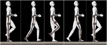
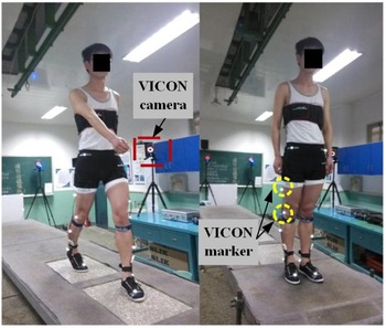
A human model with 170 cm height and 70 kg weight was set as the study subject, whose thigh length was about 380 mm, calf-length approximately 400 mm, and ankle height about 80 mm. The motion simulation process is shown in Fig. 6. The input of joint trajectories was obtained by human gait experiments. A healthy subject with the age of 25, the weight of 70 kg, and the height of 170 cm is recruited for the experiment, just as shown in Fig. 7. Before the gait experiment, all subjects were given a detailed explanation of the test content and signed a consent form for voluntary participation in the experiment. The subjects had no surgery, no history of lower extremity trauma, no balance problems, or neural muscular disorders within the past six months. A written consent is obtained from the subject. The test environment was a linear walkway of 5 m in length and 1 m in width. The kinematic parameters were acquired by VICON acquisition system(Oxford Metrics Ltd, Oxford, UK). The data acquisition frequency is 1200 Hz.
Simulation process of human-machine coupling model.

Gait experiment diagram.

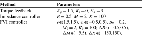
To verify the effectiveness and superiority of the proposed method, the simulation results are compared with those of torque feedback controller [Reference Zhang, Cheah and Collins32], impedance controller [Reference Li, Liu, Yan, Zhang, Li and Zhang33], and FVI controller [Reference Zhang, Wu, Chen, Wu and Liu34]. And the parameters of each control method are set, as shown in Table II. The excellent agreement between the reference trajectory and the actual trajectory illustrates the effectiveness of the measurement and control methods.
The parameters of each controller.

The RBF neural network includes three layers. The input layer contains two nodes with hip error function and knee error function; the hidden layer uses Gaussian basis function as the excitation function, the center vector is [−2 −1 0 1 2], and the width is 0.5; the adaptive rate is taken as 30. The root mean square accuracy was set to 0.01 as the termination condition of the RBF neural network. The moment coefficient of 0.8 is selected, and the simulation is performed at a speed of 0.2 m/s.
4.2. Simulation results analysis
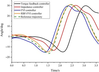
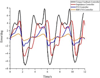
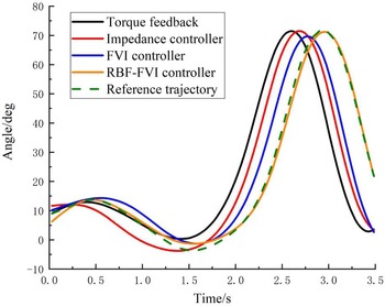
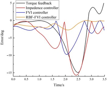
The joint trajectory tracking results of each controller and trajectory error results are shown in Figs. 8, 9, 10 and 11, respectively. When the traditional torque feedback control method was used to perform the motion mission, the maximum error values of the hip joint and knee joint between the exoskeleton robot and the human were 7.8 and 15.1 deg, respectively. Due to the large weight-bearing ratio of the limb, the release of human muscle force has more excellent resistance, so the tracking performance of the human joint position to the exoskeleton robot joint position is poor, and the two have a significant error. The angle deviation needs to be reduced by impedance relationship adjustment. Compared with the torque feedback control system without the impedance control adjustment module, the exoskeleton robot obtained by impedance control has a smaller range of error in the joint angle with the human model. The maximum error of the exoskeleton robot and human hip joint angle is 4.3 deg. This indicates that the exoskeleton robot control system converts the interaction force difference into angular deviation according to the change of human-machine contact force and adjusts the input torque in real-time. The exoskeleton robot provides greater torque support during the limb muscle strength deficiency phase and improves human tracking performance. The maximum angle error values of the hip joint and knee joint obtained based on the fuzzy impedance control method were 3.2 and 9.2 deg, respectively. The error range of the joint angle between the exoskeleton robot and human model is smaller, indicating that the impedance controller with real-time adjustment of impedance parameters improves the control system’s control accuracy and the human-machine coupling suppleness better. After adding the neural network error compensation function module, the maximum angle error values of the hip joint and knee joint were reduced to 2.4 and 2.2 deg, respectively. This indicates that the neural network compensation has a good suppression effect on the uncertainty term of the system.
Hip trajectory tracking results of each controllers.

Trajectory error results of hip joint.

Knee trajectory tracking results of each controllers.

Trajectory error results of knee joint.

5. Human-machine coupling experiments
5.1. Experimental platform
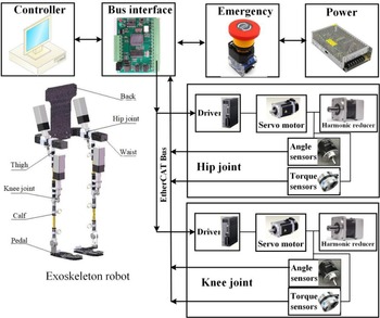
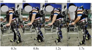
Human-machine coupling experiments are conducted to demonstrate the functionality of the proposed control method. The exoskeleton robot platform is shown in Fig. 12. The joint motion range of the exoskeleton is 20° flexion and 40° extension for the hip joint, and 70° flexion and 0° extension for the knee joints, and 0° plantarflexion and 20° dorsiflex for ankle joints. The control system consists of the data processor Raspberry Pi and the motion controller STM32F103. Raspberry Pi is used to process data collected from angle sensors (AD36/1217AF. ORBVB, Hengstler, Germany) and torque sensors(TRX-50N·m, Italy). The communication mode between the data processor and motion controller is parallel port communication. The motion controller controls the motors through the controller area network Fieldbus. A healthy subject with the age of 25, the weight of 68 kg, and the height of 170 cm is recruited for the experiment. A written consent is obtained from the subject. For safety reasons, if the angle of the exoskeleton is greater than the allowable value, the exoskeleton will be forced to stop moving by software. In addition, the subjects could cut off the power through the emergency switch button. We intercepted the complete gait course of the left lower limb during the swing phase. The video capture of the human experiment is shown in Fig. 13. The time of a complete gait cycle is 3.5 s. The experiment demonstrates that the exoskeleton robot can effectively assist the human body to realize stable walking.
The exoskeleton robot platform.

Video screenshots of the human experiment.

5.2. Human-machine system testing
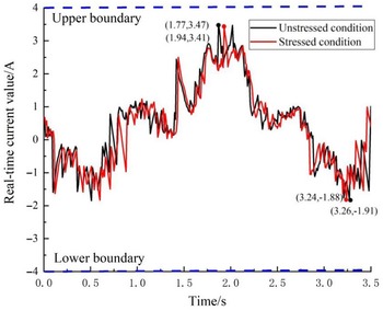
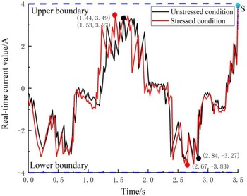
A current safety threshold is set to ensure the safety of the contact force between the exoskeleton and the subject. When the human-machine contact force makes the current within the threshold value, the movement of the joint does not stop. When the contact force exceeds the current threshold, the joint stops moving. When the human-machine contact force becomes larger, the joint torque of the exoskeleton will be correspondingly larger to resist the obstructive force exerted by the human body, and the current output will become larger at this time. The system simultaneously detects whether the current of each joint exceeds the threshold. According to the relationship between torque and power of servo motor,
 \begin{equation} \tau _{m}=\frac{9550P}{n} \end{equation}
where P is the power of motor, P = UI, U is voltage of motor, I is current of motor. n is rational speed of motor. The current is proportional to the torque. The excessive torque output may cause secondary injury to the wearer. Generally, the torque required for joint movement does not exceed 200 N.m. According to the ammeter test, when the torque value reaches 200 N.m, the current value is about 4A. Hence, the current safety threshold was set as 4A.
We conducted experiments on the exoskeleton under conditions of unloaded(red line) and loaded(black line). The real-time current value of hip joint and knee joint are shown in Figs. 14 and 15, respectively. When the exoskeleton is in continuous contact with the subject, the current value will increase with the contact force (resistance torque) compared to the unstressed condition. We found that the current was not exceeded the current safety threshold during the entire gait cycle, indicating that the coupling performance of the human-machine system was good. To test the system’s safety, we let the subject deliberately increase the range of hip joint motion to increase the human-machine contact force. Then, the joint will stop at the point S when the current generated by the contacted force exceeds the threshold value, just as shown in Fig. 15. The test ensures the safety of the exoskeleton system.
Real-time currents in hip joint when in stressed and unstressed conditions.

Real-time currents in knee joint when in stressed and unstressed conditions.

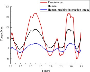
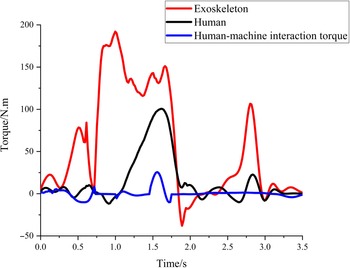
We analyzed the variation of the human joint torque, exoskeleton joint torque, and human-machine interaction torque, respectively, and the experimental results are shown in Figs. 16 and 17. It can be seen that the torque output curves of the exoskeleton and the human remain the same trend under the action of the proposed controller in this study. And the human torque always remains at a lower torque output, which is due to the exoskeleton robot compensating the required torque of the human body. It is worth noting that at 1.5 s, the human knee joint torque increases suddenly, and the exoskeleton joint torque decreases sharply, which is because the exoskeleton robot’s motion control has a specific time delay behavior at the moment of phase transition and fails to make the symbolic human intention action in time. At this time, the human-machine interaction torque also increases accordingly. We found that this situation cannot be avoided after several experiments, which is the critical problem we will solve next. The overall tendency is smooth in term of the human-machine interaction torque, and the average values of interaction torque of hip joint and knee joint are 3.215 and 2.374 N.m, indicating that the control algorithm proposed in this study can achieve stable and smooth walking.
Torque value of hip joint.

Torque value of knee joint.

6. Conclusion
In the actual rehabilitation exercise process, the movement between the lower limb rehabilitation exoskeleton and the patient must not be completely consistent, which makes the interaction force between the exoskeleton robot and the patient, and the compliance control can reduce the interaction force between the exoskeleton robot and the patient. In this study, a 6 DoFs exoskeleton robot is designed, and the exoskeleton dynamics analysis is conducted. A human-machine coupling model of the exoskeleton robot based on the spring-damping model was established. To meet the needs of patients’ rehabilitation training, a fuzzy radial impedance (RBF-FVI) controller is proposed to satisfy human motion laws. The controller includes a fuzzy position control module and an outer-loop impedance control module. Through simulation experiments, it is demonstrated that the control method proposed in this research is significantly better than other traditional control methods in trajectory following. In this study, human-machine wear experiments are conducted. The experimental results show that the exoskeleton robot system designed in this study can assist the human body to achieve stable and smooth walking. According to the experimental results, there is a sudden change of torque during the gait phase transition, which requires further optimization of the exoskeleton robot structure and control method. This will be our future research priority. In addition, we also plan to conduct human-machine experiments on stroke patients to further validate the effectiveness of the robotic system designed in this study.
Authors contributions
All authors have made substantial contribution. The first author Peng Zhang designed the experiment scheme, analyzed the experimental results, and wrote the paper. Corresponding author Junxia Zhang and Ahmed Elsabbagh modified the paper.
Funding
This work was supported in part by the Hundred Cities and Parks Project-Nutrition Health Key Technology and Intelligent Manufacturing (No. 21ZYQCSY00050), Tianjin Science and Technology Support Plan (No. 20JCYBJC01430) and China Scholarship Council.
Conflicts of interest
The work described has not been submitted elsewhere for publication, in whole or in part, and all the authors listed have approved the manuscript that is enclosed.