1. Introduction
Predicting geothermal fluid flow at depth is the main target for geothermal exploration. As extensively described in recent years, the circulation of geothermal fluids in both continental and oceanic crustal settings is mainly controlled by fracture networks related to fault zones (e.g. Curewitz & Karson, Reference Curewitz and Karson1997; Cox et al. Reference Cox, Knackstedt, Braun, Richards and Tosdal2001; Faulds et al. Reference Faulds, Coolbaugh, Blewitt and Henry2004; Rowland & Sibson, Reference Rowland and Sibson2004; Zucchi et al. Reference Zucchi, Brogi, Liotta, Rimondi, Ruggieri, Montegrossi, Caggianelli and Dini2017; Liotta et al. Reference Liotta, Brogi, Ruggieri, Rimondi, Zucchi, Helgadóttir, Montegrossi and Friðleifsson2020; Brogi et al. Reference Brogi, Alçiçek, Liotta, Capezzuoli, Zucchi and Matera2021). In this view, fluid flow (Liotta et al. Reference Liotta, Brogi, Ruggieri and Zucchi2021) can be concentrated in the fault damage zones (e.g. Faulds et al. Reference Faulds, Coolbaugh, Vice and Edwards2006; Cashman et al. Reference Cashman, Faulds and Hinz2012) and/or laterally extended into buried reservoirs, hydraulically connected with the permeable fault zone (e.g. Romagnoli et al. Reference Romagnoli, Arias, Barelli, Cei and Casini2010; Liotta & Brogi, Reference Liotta and Brogi2020). In this latter case, permeability can be enhanced by fluid–rock interaction (Yasuhara et al. Reference Yasuhara, Polak, Mitani, Grader, Halleck and Elsworth2006; Brogi et al. Reference Brogi, Liotta, Ruggieri, Capezzuoli, Meccheri and Dini2016; Vezzoni et al. Reference Vezzoni, Dini and Rocchi2016; Hantsche et al. Reference Hantsche, Kouzmanov, Milenkov, Vezzoni, Vassileva, Dini, Sheldrake, Laurent and Guillong2021) and/or by pressure-value fluctuations, momentarily reaching or exceeding the lithostatic pressure (Sibson, Reference Sibson2000).
These cases are particularly effective within levels of regional relevance (i.e. crustal detachments; e.g. Liotta & Brogi, Reference Liotta and Brogi2020), but also in texturally heterogeneous rock masses, as is the case for siliciclastic and/or carbonate rocks (Ducoux et al. Reference Ducoux, Branquet, Jolivet, Arbaret, Grasemann, Rabillard, Gumiaux and Drufin2016), which can behave as lateral traps where geothermal fluids are stored (Dini et al. Reference Dini, Innocenti, Rocchi, Tonarini and Westerman2002). Examples are from the active geothermal fields of Italy (Larderello and Monte Amiata areas; Batini et al. Reference Batini, Brogi, Lazzarotto, Liotta and Pandeli2003), western Anatolia (Denizli and Gediz basins; Alçicek et al. Reference Alçiçek, Bülbül and Alçiçek2016, Reference Alçiçek, Bülbül, Brogi, Liotta, Ruggieri, Capezzuoli, Meccheri, Yavuzer and Alçiçek2018, Reference Alçiçek, Bülbül, Yavuzer and Alçiçek2019), the Geyser area (California; McLaughlin & Donnelly-Nolan, Reference McLaughlin and Donnelly-Nolan1981; Stanley & Blakely, Reference Stanley and Blakely1995) and the Taupo zone (New Zealand; Rowland & Sibson, Reference Rowland and Sibson2004).
In these contexts, the size and efficiency of the fluid flow depends on three main factors (Barbier, Reference Barbier2002; Rowland & Simmons, Reference Rowland and Simmons2012; Jolie et al. Reference Jolie, Moeck and Faulds2015; Craig et al. Reference Craig, Faulds, Hinz, Earney, Schermerhorn, Siler, Glen, Peacock, Coolbaugh and Deoreo2021; Liotta et al. Reference Liotta, Brogi, Ruggieri and Zucchi2021): (i) maintenance of permeability, due to the tectonic activity; (ii) preservation of the hydraulic connectivity between feeding conduits (e.g. faults) and lateral permeable levels; and (iii) continuous renewal of the fluids, maintaining the chemical-aggression properties during their flow through the rocks. Nevertheless, although such factors play the most relevant role, the lithological heterogeneities and geometrical setting of the lateral permeable levels, as developed before the geothermal event, may have an impact on the lateral migration of the fluids (Liotta et al. Reference Liotta, Brogi, Ruggieri and Zucchi2021). It derives that the interplay between inherited structures and faults, active during fluid flow, is pivotal for the understanding of any geothermal system.
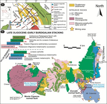
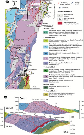
To focus on these issues, we analysed the case of the Neogene (late Messinian; Lippolt et al. Reference Lippolt, Wernicke and Bahr1995; Liotta et al. Reference Liotta, Brogi, Meccheri, Dini, Bianco and Ruggieri2015; Wu et al. Reference Wu, Stuart, Heizler, Benvenuti and Hu2019; Spiess et al. Reference Spiess, Langone, Caggianelli, Stuart, Zucchi, Bianco, Brogi and Liotta2021) exhumed geothermal system exposed on eastern Elba Island (Fig. 1), where Fe-ore deposits (Tanelli et al. Reference Tanelli, Benvenuti, Costagliola, Dini, Lattanzi, Manieri, Mascaro and Ruggieri2001; Dini, Reference Dini2003) are embedded in fault damage zones and peripheral siliciclastic rocks, which experienced intense folding during the tectonic events of the Northern Apennines orogenesis. For this purpose, we considered exposures within the Rio Marina mining district, focusing on the Valle Giove mine and Rio Albano mining area where Fe-ore deposits (mostly haematite and pyrite; Tanelli et al. Reference Tanelli, Benvenuti, Costagliola, Dini, Lattanzi, Manieri, Mascaro and Ruggieri2001; Dini, Reference Dini2003; Benvenuti et al. Reference Benvenuti, Dini, D’Orazio, Chiarantini, Corretti and Costagliola2013) were exploited for centuries (Fig. 2).
(a) Structural sketch-map of the Northern Apennines and Northern Tyrrhenian Sea showing inner and outer zones. The main Pliocene–Quaternary basins, transfer zones, Neogene–Quaternary volcanic complexes, intrusive magmatic bodies and metamorphic units are highlighted. (b) Structural sketch-map of Elba Island and location of the study area (in the black dotted square). The different tectonic units and the main low-angle and high-angle normal faults are highlighted.

(a) Geological map of the study area indicating the Rio Albano and Valle Giove mining areas. Continental and oceanic units as in Figure 1. (b) Geological sections across the mining areas; their traces are indicated in (a).

2. Methodology
Structural and kinematic fieldwork, integrated with a detailed geometrical analysis of the mineralized bodies, was carried out in the study areas (Valle Giove and Rio Albano mining areas; Fig. 2). Detailed geological maps of the mining areas were obtained by both using the FieldMove software by PETEX (petroleum experts, https://www.petex.com) and reporting data on topographic maps manually. The analyses of fault kinematics and geometry were processed using Stereonet V11 and FaultKinMac V8 software (http://www.geo.cornell.edu/geology/faculty/RWA/programs). Secondary permeability and the derived efficient porosity of representative fault zones were computed by applying the scan line and scan box methodologies, as described in Section 6.
Mineralized rock samples were collected throughout the study areas to describe their hydrothermal paragenesis. To visualize microstructures and mineral phases, a petrographic investigation was performed on thin-sections from vein and rock samples using a Zeiss-Axioplane polarizing optical microscope. In addition, scanning electron microscope (SEM) observations and microanalysis (EDS, energy dispersive X-ray spectrometry; Oxford-Link) of selected minerals were achieved at the Department of Earth and Geoenvironmental Sciences (University of Bari) using a ZEISS EVO 50XVP instrument coupled with an EDS detector.
3. Geological framework
Elba Island (Fig. 1a) is an exhumed sector of the inner Northern Apennines belt, formed by the convergence and collision between the Adria micro-plate and the Corsica–Sardinia massif (Cretaceous–early Miocene). The orogenesis produced the stacking of oceanic and continental tectonic units deriving from the palaeogeographic domains belonging to the Alpine Tethys and passive margin of Adria (Carmignani et al. Reference Carmignani, Decandia, Disperati, Fantozzi, Lazzarotto, Liotta and Meccheri1994; Vai & Martini, Reference Vai and Martini2001; Molli, Reference Molli, Siegesmund, Fügenschuh and Froitzheim2008). At least seven tectonostratigraphic units have been described on Elba Island (Bianco et al. Reference Bianco, Brogi, Caggianelli, Giorgetti, Liotta and Meccheri2015), including three of oceanic pertinence (Fig. 1b). Since early Miocene time, the inner Northern Apennines (and Elba Island) has been affected by eastward-migrating extensional tectonics (Bartole, Reference Bartole1995; Brogi et al. Reference Brogi, Lazzarotto, Liotta and Ranalli2005; Brogi & Liotta, Reference Brogi and Liotta2008; Barchi, Reference Barchi, Beltrando, Peccerillo, Mattei, Conticelli and Doglioni2010). The opening of the Tyrrhenian basin and the present crustal and lithospheric thicknesses (17–22 and 30–50 km, respectively; Calcagnile & Panza, Reference Calcagnile and Panza1981; Locardi & Nicolich, Reference Locardi and Nicolich1992; Cassinis et al. Reference Cassinis, Scarascia and Lozej2003; Moeller et al. Reference Moeller, Grevemeyer, Ranero, Berndt, Klaeschen, Sallares, Zitellini and De Franco2013) are the main evidence of this extensional evolution. Since Langhian time, the migration of extensional tectonics has been accompanied by magmatism mostly deriving from the mixing of crustal and mantle melts (Serri et al. Reference Serri, Innocenti and Manetti1993; Peccerillo, Reference Peccerillo2003; Dini et al. Reference Dini, Gianelli, Puxeddu and Ruggieri2005). Emplacement and heat loss of late Miocene plutons (Westerman et al. Reference Westerman, Dini, Innocenti, Rocchi, Breitkreuz and Petford2004; Rocchi et al. Reference Rocchi, Westerman, Dini and Farina2010; Caggianelli et al. Reference Caggianelli, Ranalli, Lavecchia, Liotta, Dini, Llan-Fúnez, Marcos and Bastida2014, Reference Caggianelli, Zucchi, Bianco, Brogi and Liotta2018; Spiess et al. Reference Spiess, Langone, Caggianelli, Stuart, Zucchi, Bianco, Brogi and Liotta2021), such as the Monte Capanne and Porto Azzurro magmatic complexes on Elba Island (Fig. 1b), determined widespread hydrothermal effects and the formation of skarn-related Fe-ore deposits in the wall and roof rocks (Tanelli et al. Reference Tanelli, Benvenuti, Costagliola, Dini, Lattanzi, Manieri, Mascaro and Ruggieri2001; Dini, Reference Dini2003; Benvenuti et al. Reference Benvenuti, Dini, D’Orazio, Chiarantini, Corretti and Costagliola2013). Because of the uplift and exhumation of Elba Island, rocks related to the middle and upper crust, including the magmatic intrusions of Monte Capanne (∼7 Ma; Westerman et al. Reference Westerman, Dini, Innocenti, Rocchi, Breitkreuz and Petford2004; Gagnevin et al. Reference Gagnevin, Daly, Horstwood and Whitehouse2011; Barboni et al. Reference Barboni, Annen and Schoene2015) and Porto Azzurro (6.4–5.9 Ma; Maineri et al. Reference Maineri, Benvenuti, Costagliola, Dini, Lattanzi, Ruggieri and Villa2003; Gagnevin et al. Reference Gagnevin, Daly, Horstwood and Whitehouse2011; Spiess et al. Reference Spiess, Langone, Caggianelli, Stuart, Zucchi, Bianco, Brogi and Liotta2021), are now exposed. The relevant circulation of hydrothermal fluids (Liotta et al. Reference Liotta, Brogi, Meccheri, Dini, Bianco and Ruggieri2015 with references therein) during the cooling of the Porto Azzurro pluton (Orlando et al. Reference Orlando, Ruggieri, Chiarantini, Montegrossi and Rimondi2017; Zucchi et al. Reference Zucchi, Brogi, Liotta, Rimondi, Ruggieri, Montegrossi, Caggianelli and Dini2017; Zucchi, Reference Zucchi2020) mainly produced masses of Fe-oxides and Fe-sulphides variably associated with chlorite–quartz–adularia gangues and hedenbergite–ilvaite–garnet skarns (Tanelli et al. Reference Tanelli, Benvenuti, Costagliola, Dini, Lattanzi, Manieri, Mascaro and Ruggieri2001; Dini, Reference Dini2003; Benvenuti et al. Reference Benvenuti, Dini, D’Orazio, Chiarantini, Corretti and Costagliola2013). The mineralization event was controlled by extensional and transfer faults, which also played a role in the emplacement and progressive exhumation of the Porto Azzurro monzogranite (Keller & Pialli, Reference Keller and Pialli1990; Duranti et al. Reference Duranti, Palmeri, Pertusati and Ricci1992; Pertusati et al. Reference Pertusati, Raggi, Ricci, Duranti and Palmeri1993; Dini et al. Reference Dini, Westerman, Innocenti, Rocchi, Thomson and Petford2008; Smith et al. Reference Smith, Holdsworth and Collettini2011; Liotta et al. Reference Liotta, Brogi, Meccheri, Dini, Bianco and Ruggieri2015; Spiess et al. Reference Spiess, Langone, Caggianelli, Stuart, Zucchi, Bianco, Brogi and Liotta2021). Despite the clear epigenetic characters (replacement bodies, veins and stockworks, structural control, variable age of host rocks, widespread chloritization), some authors (see the review by Tanelli et al. Reference Tanelli, Benvenuti, Costagliola, Dini, Lattanzi, Manieri, Mascaro and Ruggieri2001) proposed a Triassic syngenetic origin for the Fe-ores, limiting the role of late Miocene magmatic–hydrothermal systems to local remobilization and recrystallization.
4. Study areas
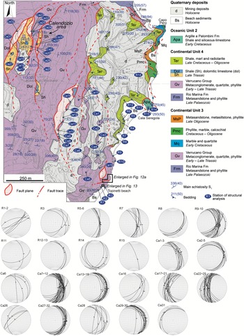
Assuming the Fe-ore bodies’ distribution as a feature for understanding the palaeo-fluid pathways, two key areas (Fig. 2) have been considered, based on their different geological features: (i) the Valle Giove stope, consisting of a wide mining exposure, where we reconstructed the relationships between mineralization and feeding fractures, and the impact of the inherited, pre-existing structures in controlling the fluid lateral pathways; and (ii) the Calendozio stope and Topinetti area (included in the larger Rio Albano mining area; Fig. 2), where we reconstructed Fe-ore bodies (i.e. palaeo-fluid flow) formed in fault zones.
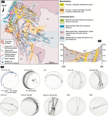
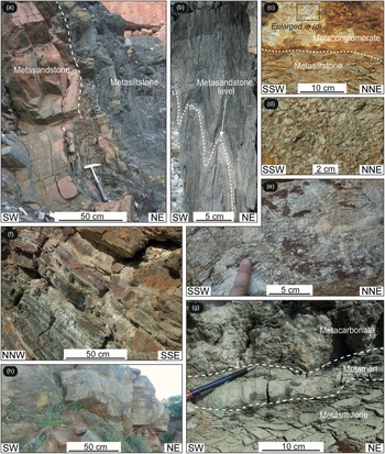
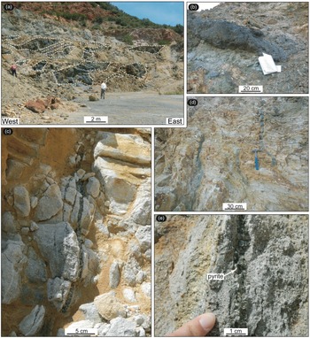
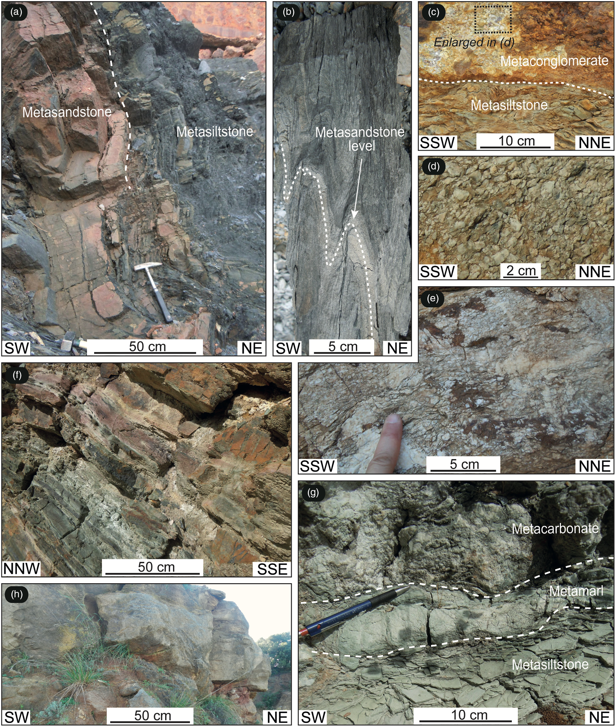
Concerning the Valle Giove area (Fig. 3), the deepest exposed unit consists of graphitic black to grey phyllite, metasiltstone and quartz-metasandstone with quartz-metaconglomerate at the top (Figs 3, 4a–c), deriving from upper Carboniferous–Permian marine sediments (Rio Marina Formation in Bortolotti et al. Reference Bortolotti, Fazzuoli, Pandeli, Principi, Babbini and Corti2001; Sirevaag et al. Reference Sirevaag, Jacobs, Ksienzyk, Rocchi, Paoli, Jørgensen and Košler2016; Spina et al. Reference Spina, Capezzuoli, Brogi, Cirilli and Liotta2019). The Rio Marina Fm is overlain by quartz-metaconglomerate, metasandstone and violet to greenish phyllite and metasiltstone (Fig. 4d–f) belonging to the Triassic continental succession (Verrucano Group in Bortolotti et al. Reference Bortolotti, Fazzuoli, Pandeli, Principi, Babbini and Corti2001). At the top of the Verrucano Group, marine early Mesozoic fine-grained metacarbonate and metasiltstone (i.e. ‘calcari di Valle Giove’ and ‘calcari di Vigneria’ in Gilliéron, Reference Gilliéron1959; Deschamps et al. Reference Deschamps, Dagallier, Macaudier, Marignac, Maine and Saupé1983) occur as a tectonic slice within the metasiliclastic succession of the Verrucano Group (Fig. 4g, h).
(a) Geological and structural sketch-map of the Valle Giove stope showing the ore body distribution, F1 and F2 folds, main faults and stations of structural analysis. (b) Geological section across the stope. (c) Stereographic diagrams (lower hemisphere, equal-area projection) of the main structures collected on the indicated structural stations. For each stereoplot the considered structural stations are indicated.

Photographs of the main lithotypes exposed in the study areas. (a) Alternated upper Permian quartz-metasandstone and metasiltstone with graphitic black to grey phyllite (Rio Marina Fm). (b) Tight folds affecting upper Permian quartz-metasandstone and metasiltstone (Rio Marina Fm). (c) Contact separating upper Permian grey metasiltstone, at the bottom, and quartz-metaconglomerate, at the top (Rio Marina Fm). (d) Detail of quartz-metaconglomerate at the top of the upper Permian succession (Rio Marina Fm). (e) Triassic quartz-metaconglomerate (Verrucano Group, Anageniti auct.). (f) Alternated Triassic violet and greenish metasiltstone and metasandstone (Verrucano Group). (g) Mesozoic marine fine-grained metacarbonate, metamarl and metasiltstone (Calcari di Valle Giove auct.). (h) Mesozoic metacarbonate at the top of the succession (Calcari di Valle Giove auct.).
As concerns the Rio Albano mining area (Figs 2, 5), the deepest unit is still the Rio Marina Fm, unconformably covered by the metasiliciclastic rocks of the Verrucano Group. In the Calendozio area (Fig. 5), Upper Triassic marine dolostone conformably overlies reddish and yellowish metasiltstone and phyllite referred to the Verrucano Group (Fig. 5).
Geological map of the Rio Albano mining area with stereographic diagrams (lower hemisphere, equal-area projection) of data collected at the structural stations reported on the map.

The successions of the Verrucano Group and Rio Marina Fm exposed in the Valle Giove and Rio Albano areas were strongly affected by hydrothermal alteration (mainly chloritization and silica dissolution/precipitation) and ore deposition (haematite, magnetite, pyrite, with minor deposition of base metal sulphides). At the surface and along contacts with dolostone–limestone, pyrite ore bodies were deeply oxidized to Fe-hydroxides (mainly goethite). Mineralogical and microstructural analyses integrated with fluid inclusion analyses (Deschamps et al. Reference Deschamps, Dagallier, Macaudier, Marignac, Maine and Saupé1983) of a haematite + adularia assemblage in the Valle Giove mine pointed out that Fe-oxide ores formed at a relatively high temperature (>310 °C) by the interaction between saline hydrothermal fluids and siliciclastic rocks. The haematite–adularia assemblage was dated to 5.39 ± 0.46 Ma and 5.53 ± 0.14 Ma by Lippolt et al. (Reference Lippolt, Wernicke and Bahr1995) and Wu et al. (Reference Wu, Stuart, Heizler, Benvenuti and Hu2019), respectively.
5. Ore deposits
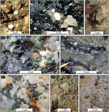
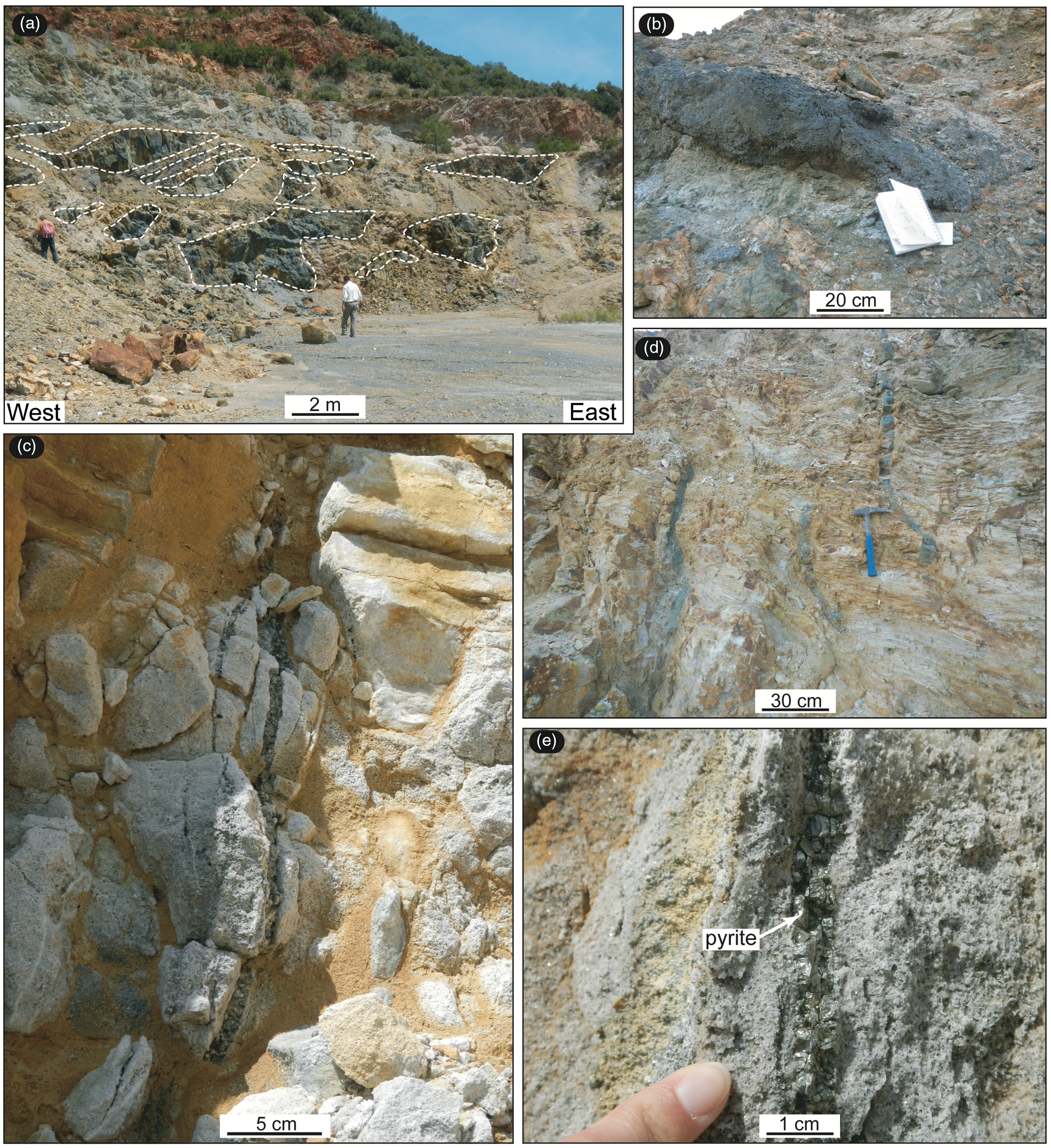
In the Valle Giove stope, two types of haematite ore bodies have been exploited and are already recognizable: (i) small lens-shaped, massive bodies made up of haematite, quartz and pyrite interbedded in the Verrucano Group metasiliciclastic rocks (Fig. 6a, b) and (ii) large, sub-vertical, pipe-like bodies made up of haematite, pyrite and chlorite, showing a brecciated structure and frequent voids lined by euhedral crystals of haematite and pyrite (Fig. 6c–e). Most of the production came from the first type of ore body, although the ore quality of the minor lenses was higher (less amounts of pyrite and chlorite). Along the benches of the Valle Giove open pit, haematite lenses are still well exposed. The pipe-like bodies were largely exploited before 1981, but some residues occur in the northern zone of the open pit where small excavations have been performed by the Mining Park to collect mineral specimens.
(a) Small lens-shaped, massive bodies of haematite + quartz + pyrite interbedded in the Verrucano metasiltstone from the Valle Giove stope. (b) Detail of a massive body of haematite + quartz. (c, d) Centimetre-thick sub-vertical haematite + quartz vein crossing quartz-metaconglomerate of the Verrucano Group. (e) Centimetre-thick sub-vertical pyrite vein crossing quartz-metaconglomerate of the Verrucano Group.
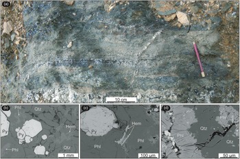
Pipe-like bodies are pluri-decametric breccia structures filled by blocks (centimetre to several metres) of foliated metasiltstone–phyllite that were totally replaced by an assemblage of chlorite, epidote, phlogopite, haematite, pyrite, adularia and quartz (Figs 7, 8). The net result is a greenish, soapy rock that usually maintains the original foliated-layered structure of the Verrucano Group host rock. At the thin-section scale, the mineral assemblage of the greenish volumes is composed by green phlogopite and chlorite. Phlogopite is the unusual mineral as its formation in geothermal and hydrothermal environments is uncommon (e.g. Cavarretta et al. Reference Cavarretta, Gianelli, Scandiffio and Tecce1985; Zhang, Reference Zhang1986; Belkin et al. Reference Belkin, Cavarretta, De Vivo and Tecce1988). Nonetheless, it is well constrained to low-temperature conditions with microthermometry in fluid inclusions by Belkin et al. (Reference Belkin, Cavarretta, De Vivo and Tecce1988) for other areas and by Deschamps et al. (Reference Deschamps, Dagallier, Macaudier, Marignac, Maine and Saupé1983) for the study areas. Our analyses highlight phlogopite occurring in radially arranged aggregates grown along the vein walls or in association with pyrite, quartz and haematite (Fig. 8). Deschamps et al. (Reference Deschamps, Dagallier, Macaudier, Marignac, Maine and Saupé1983), in the Valle Giove stope, described green biotite spherulites that may be compared to the ones we observed in veins. Indeed, some microanalyses provided by Deschamps et al. (Reference Deschamps, Dagallier, Macaudier, Marignac, Maine and Saupé1983) can also be classified as phlogopites. Based on our SEM/EDS analyses (Table 1), green phlogopites show an unusual Si:IVAl ratio greater than 3, seldom reported in literature (e.g. Deschamps et al. Reference Deschamps, Dagallier, Macaudier, Marignac, Maine and Saupé1983; Brigatti & Poppi, Reference Brigatti and Poppi1993). In addition, chemical analyses suggest that the interlayer site is not fully occupied.
Examples of the hydrothermal mineral assemblage occurring at the Valle Giove stope. Except for adularia, mineral abbreviations according to Kretz (Reference Kretz1983). Adl – adularia; Cc – calcite; Hem – haematite; Py – pyrite; Qtz – quartz.

(a) Foliated quartz-metasiltstone totally replaced by chlorite + phlogopite + haematite + pyrite + adularia + quartz assemblage. (b–e) SEM–BSE images showing compositional and textural details of the phlogopite-bearing levels: (b) irregular phlogopite dispersed within a quartz–pyrite-rich zone; (c) radial aggregates of phlogopite close to polygonal section of pyrite; (d) comb fabric of phlogopite in vein having small pyrite grains along its axis. Mineral abbreviation according to Kretz (Reference Kretz1983). Hem – haematite; Phl – phlogopite; Py – pyrite; Qtz – quartz.

Averaged chemical composition of phlogopite based on six EDS microanalysis spots

Structural formula (apfu) based on 11 oxygens. Standard deviation in parentheses. n.d. – not detected, i.e. below the detection limit.
This feature can be consistent with XIIK+→XIIH3O+ substitution, found in micas from metamorphic environments (Brigatti et al. Reference Brigatti, Malferrari, Laurora, Elmi, Brigatti and Mottana2011) and with a talc component within the phlogopite structure.
Hydrothermal alteration, as well as fabric re-working, increases from the borders to the core of the pipes. Here the structures are dominated by haematite–pyrite–chlorite infill, with large pockets (up to 0.5 m3) where open space crystallization produced euhedral crystals of pyrite and haematite up to 10 cm in diameter. Haematite–pyrite vein stockworks propagate from the core to the border of the pipes, cross-cutting both the deeply altered blocks and the less-altered wall rocks. Valle Giove pipes are controlled by the interference between NW–SE and NNE–SSW tectonic structures. Exploratory drilling indicated that the ore pipes are restricted to the Verrucano succession, and they do not have deep roots into the underlying Permian metasiliciclastic succession. Permian rocks have been found to be fractured and hydrothermally altered, but they contain just low-grade pyrite disseminations and pyrite–haematite veinlets.
Lens-shaped, massive haematite–quartz–pyrite bodies derive from pervasive replacement of quartzite–metaconglomerate lenses originally interbedded in the metasiliciclastic rocks and phyllite of the Verrucano Group. This is supported by the observation of quartzite and metaconglomerate relics with scallop-like concave surfaces embedded in the haematite–quartz–pyrite lenses. The metasiltstone and phyllite envelope is usually chloritized and locally cut by haematite–pyrite stockworks. Ore lenses follow the overall attitude of the main foliation affecting the Verrucano Group (dipping to the west), and they are connected to the main ore-pipe alignment.
At Rio Albano mine (Calendozio stope and Topinetti area), haematite and pyrite are hosted within fault zones, in some cases cementing the cataclasite, as later described. Locally, vein stockworks and ore pipes have also been observed.
6. Deformation
Keeping in mind that the hydrothermal mineral assemblages represent clear evidence of palaeo-fluid circulation within the fault zones and the lateral metasiliciclastic rocks, for the sake of clarity, deformation is described in three different sections dealing with (i) the relationships between faults, palaeo-fluids and mineralization, (ii) their implications on the secondary permeability and (iii) the role of inherited structures in controlling the lateral migration of palaeo-fluids.
6.a. Faults, palaeo-fluids and mineralization
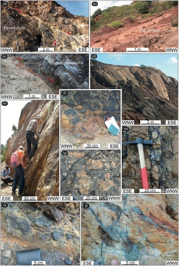
Two main mineralized fault systems have been recognized in both study areas (Figs 3, 5). The first fault system is defined by NNE-trending, E-dipping low- (15–30°) to middle- (30–50°) angle faults. These are well exposed in the Rio Albano area, where fault planes control the morphology, and in the northeastern part of the Valle Giove stope (Fig. 3). The fault architecture is defined by slip surfaces and fault cores up to 50 cm thick, characterized by cataclastic rocks cemented by haematite–quartz–adularia and/or Fe-hydroxides (Fig. 9a–g). Damage zones consist of fractured rock volumes up to 10 m thick mainly cross-cut by haematite veins (Fig. 9h). In some cases, the hydrothermal mineral assemblage was involved in progressive deformation, hence, in turn, comminuted and cemented by newly formed haematite/magnetite (Fig. 9i).
Examples of mineralized faults. (a) Middle-angle normal fault deforming the Triassic metaconglomerate and metasiltstone of the Verrucano Group exposed in the Topinetti area. (b) Middle-angle normal fault controlling the slope morphology along the sea coast of the Topinetti area. (c) Normal fault dissecting haematite and relative hydroxides exposed at the Calendozio stope. (d) Conjugate high-angle normal faults exposed at the Calendozio stope. (e) High-angle normal fault cutting the quartz-metaconglomerate of the Verrucano Group at the Valle Giove stope. (f) Mineralized damage zone associated with high-angle normal fault at the Calendozio stope. (g) Cataclasite cemented by haematite exposed in the Topinetti area. (h) Haematite shear veins developed in the damage zone of the middle-angle normal fault in the Topinetti area. (i) Brecciated haematite and pyrite within the massive Fe-ore body characterizing the Valle Giove stope. (j) Example of breccia cemented by haematite related to the hydrofracturing process.

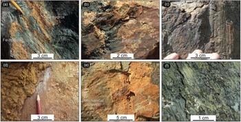
Shearing was often accompanied by hydrofracturing during faulting events (Fig. 9j). Kinematic indicators consist of shear veins made up of haematite + quartz + adularia and/or epidote, calcite and quartz (Fig. 10) and slickenlines, ENE-trending and plunging dominantly (Fig. 11).
Kinematic indicators on the fault planes, consisting of (a, b) mechanical striation covered by Fe-hydroxides; (c) mechanical striation and chatter marks; (d) haematite mirror fault plane; (e) syn-kinematic adularia developed within an extensional jog; (f) syn-kinematic epidote on a fault plane. Mineral abbreviations: Adl – adularia; Ep – epidote; Fe – iron.

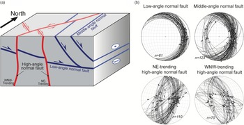
(a) Conceptual sketch showing the relationships among low-, middle- and high-angle normal faults. (b) Stereographic diagrams (lower hemisphere, equal-area projection) of the whole structural and kinematic dataset collected in the study areas.

Kinematic data have been collected at structural stations (Figs 3, 5); results are reported in Figure 11 where the structural relationships among the analysed faults are summarized.
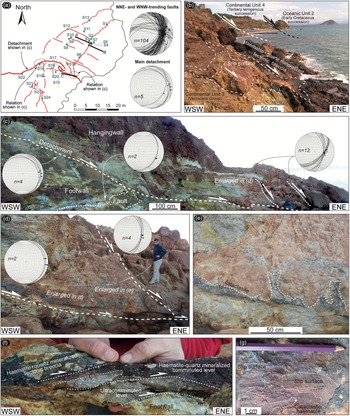
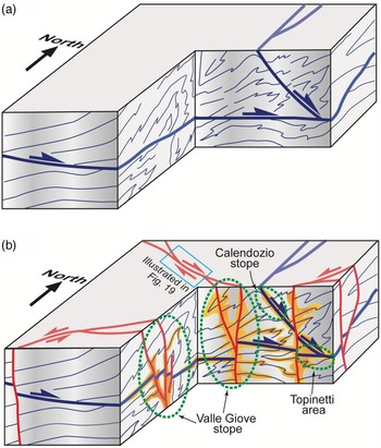
Geometrical relationships between mineralized low- and middle-angle normal faults are well exposed in the Topinetti area (Fig. 12a) where middle-angle faults (Fig. 12b) lie on low-angle ones (Fig. 12c, d), the latter representing the main detachment. Both low- and middle-angle normal faults host a common mineralization, mainly made up of cataclastic haematite and quartz, indicating a contemporaneity among fluid circulation, mineralization and fault activity (Fig. 12e–g). A tectonic transport towards the east characterizes these faults (Fig. 11).
(a) Structural sketch-map of the Topinetti area where the main structures and the stations of structural analysis are indicated. The relationships between low- and middle-angle normal faults are also highlighted. (b) Panoramic view of the Topinetti sea coast where major middle-angle normal faults are indicated. (c) Panoramic view of the Topinetti area highlighting the relationships between low- and middle-angle normal faults. (d) Detail of fault relationships enlarged from (c). (e) Enlarged area of the detachment showing a rock fault deriving from a combined effects of cataclasis and hydrofracturing processes. (f) Detail of zoned mineralized fault rock enlarged from (d). (g) Detail of kinematic indicators recognized on the detachment slip surface.

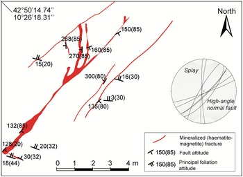
Mineralized NE- and WNW-trending high-angle normal to oblique-slip faults (Fig. 11) dissect the low-angle faults in both study areas. The NE- and WNW-trending high-angle faults host haematite + quartz mineralization in their fault zone and associated splay structures (Fig. 13). The geometric relationship between splay structures and the main fault accounts for a relevant strike-slip component. Accordingly, kinematic indicators consist of mineralized shear veins and mechanical striations, indicating a left-lateral and right-lateral oblique-slip shear sense for the NE- and WNW-trending faults, respectively (Fig. 11).
Geological sketch-map showing NE-trending high-angle normal fault with associated splay structures both mineralized mainly by haematite and magnetite.

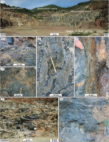
In the Valle Giove area, the principal Fe-ore bodies consist of W-dipping strata-bound bodies (Figs 3, 14a). Their areal distribution is however concentrated in a limited rock volume, WNW-oriented, where the exploitation was carried out (Fig. 14a).
(a) Panoramic view of the Valle Giove stope where the distribution of the Fe-ore bodies is indicated. (b–e) Brecciated haematite and pyrite along the WNW-striking faults. (f) Brecciated volumes of haematite + pyrite and metre-thick strata-bound body strictly confined within metasomatized metasiliciclastic levels. (g) Detail of the brecciated body shown in (f).

In this framework, the central part is formed by a massive Fe-ore body, up to 20 m thick, often composed by brecciated haematite and pyrite (Fig. 14b, c). This suggests contemporaneity among fluid circulation, mineralization and tectonic activity, distributed along the WNW-trend (Fig. 14d, e).
The Fe-ore body laterally extends forming metre-thick strata-bound bodies strictly confined within metasomatized metasiliciclastic levels (Fig. 14f, g). In these strata-bound bodies, the ore body is not cataclastic, although local minor brittle deformation can occur.
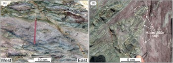
Fe-ore bodies are also surrounded by decimetre to metre thick greenish zones, where quartz, phlogopite and chlorite are the main mineral phases. These formed during a diffuse circulation of geothermal fluids that, from the fault zones, permeated into selected volumes, determining intense metasomatism in metasiliciclastic rocks with a medium to coarse grain size. In contrast, metasiltstone and phyllite are only partially altered (Fig. 15).
(a) Example of metasiltstone affected by metasomatism. The greenish zones are mainly composed by phlogopite, chlorite, haematite and quartz and formed during the diffuse circulation of geothermal fluid in selective volumes. (b) Detail of haematite pods developed within the metasomatic volumes.

6.b. Secondary permeability
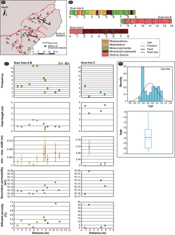
The above reported data highlight the role of fractures in determining the geothermal fluid pathways. To evaluate the permeability (k) values which favoured the fluid flow along the fault zones, and to compare the results with similar ones from active geothermal contexts, we selected the most accessible outcrops where mineralized faults are exposed, and where the exposures are useful for collecting data along scan lines and scan boxes. The study outcrops are located in the Topinetti area, close to the sea coast (Fig. 5). The methodology is based on various steps, as described in Zucchi et al. (Reference Zucchi, Brogi, Liotta, Rimondi, Ruggieri, Montegrossi, Caggianelli and Dini2017), and on the assumption that permeability can be evaluated assuming fractures as described by two spaced parallel planes (parallel plate model in Zimmerman & Bodvarsson, Reference Zimmerman and Bodvarsson1996; Nicholl et al. Reference Nicholl, Rajaram, Glass and Detwiler1999; Leung & Zimmerman, Reference Leung and Zimmermann2012). For the goals of our work, the methodological approach can be described as follows: (a) a detailed geological map at 1:100 scale of the selected area (scan area) is realized, reporting the structures to be analysed; (b) within the scan area, three scan lines are disposed (Fig. 16a, b) orthogonally to the trend of the main structures. Scan line length was up to 9 m, sufficient to quantify the minimum and maximum fracture spacing; (c) scan boxes of 0.4 m per side, regularly spaced (1 m), are then settled along each scan line. Within each scan box, fracture parameters (length, maximum and minimum aperture, frequency) were collected. Veins formed by a clear contribution of hydrofracturing (i.e. the occurrence of hydraulic breccia embedded in the mineralization) are not compatible with the parallel plate model, resulting in unreasonable values of permeability (≥10−12 m2, see scan line C in Fig. 16). To avoid this issue, we statistically considered only those results where k < 10−12 m2, thus representing the maximum possible permeability estimates, in the frame of the model we assumed.
(a) Structural map of the scan area in which scan line locations have been reported. (b) Scan line results. The blue dashes located on the scan line bars indicate the scan boxes in which geometrical data were collected. (c) Diagrams showing the results obtained by geometrical parameters collected within each scan box. In detail diagrams show: (i) frequency; (ii) total vein length; (iii) minimum and maximum aperture; (iv) secondary permeability; (v) efficient porosity versus distance. (d) Statistical distribution of the permeability values.

The measurements were therefore processed in order to fit the following equation (Zucchi et al. Reference Zucchi, Brogi, Liotta, Rimondi, Ruggieri, Montegrossi, Caggianelli and Dini2017), assuming the plate boundary model (Gale, Reference Gale and Narasimhan1982; Cox et al. Reference Cox, Knackstedt, Braun, Richards and Tosdal2001) and laminar flow (Zimmerman & Bodvarsson, Reference Zimmerman and Bodvarsson1996; Leung & Zimmerman, Reference Leung and Zimmermann2012):
 $$k = \left( {{2 \over 3} \times {{{b^3}} \over L}} \right) \times F \times {10^{ - 6}}$$
where b and L represent the mean of fracture aperture and length, respectively, and F is the factor of fracture connectivity, here considered to be 0.4 in a possible range of variation between 0 and 1, from parallel to orthogonal angular relationships among fractures (Nicholl et al. Reference Nicholl, Rajaram, Glass and Detwiler1999).
The results are reported in Figure 16c together with all collected data. In this way, permeability was computed for each scan box, considering the harmonic mean that provides the best approximation for a system dominated by long fractures. Diagrams (Fig. 16c) and statistical evaluations (Fig. 16d) indicate permeability values ranging between 5 × 10⁻¹³ and 5 × 10⁻¹⁶ m2. Efficient porosity, deriving from the ratio between the area occupied by the mineralized fractures and the area of the scan box, shows variable values encompassed between 0.02 % and 3.69 %, except for a spike of ∼35 % in correspondence with the higher permeability values along the scan line C in points (Fig. 16c), located at the intersection with a fault zone.
6.c. Inherited structures and fluids
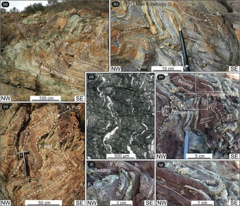
The faults and associated fluid flow (i.e. present mineralization) cross-cut all the previously formed structures. In the study areas, the inherited structures are related to two folding events, referred to as F1 and F2, respectively. The best evidence of F1/F2 interference (dominantly Type 2 in Ramsay, Reference Ramsay1967) is visible on the benches of the Valle Giove stope (Fig. 3). Here, the contact separating the Rio Marina Fm from the Verrucano Group is deformed by an F1 sub-isoclinal anticline, with a sub-vertical axial plane, NW-striking. The F1 line shows a dominant sub-vertical attitude. At outcrop scale, minor F1 folds (i.e. second-order folds) are rare and consist of decimetre to metre isoclinal folds characterized by steeply dipping axial planes and sub-vertical hinge lines (Fig. 17). A main tectonic foliation (main schistosity, S1) is associated with these folds (Fig. 17a, b). The angular relationship with the bedding (S0) is well recognizable in the fold hinge zone, whereas S1 becomes mostly parallel, or sub-parallel, to S0 in the fold limbs (Fig. 17c). S1 consists of a pervasive and penetrative slaty-type foliation (sensu Durney & Kisch, Reference Durney and Kisch1994), or penetrative slaty cleavage (sensu Williams, Reference Williams1972; Hobbs et al. Reference Hobbs, Means and Williams1976; Williams et al. Reference Williams, Means and Hobbs1977), well developed in the fine-grained lithotypes such as phyllite and metasiltstone. Analyses of thin-sections highlight that S1 is a continuous foliation (sensu Passchier & Trouw, Reference Passchier and Trouw1996) with a mineral assemblage mainly consisting of quartz + phengite + muscovite + kaolinite ± calcite ± Fe–Ti oxides (Fig. 17d). Phengite, associated with S1, displays a Si content of ∼3.5 atoms per formula unit (apfu) indicating that S1 developed during high-pressure (HP) conditions (Bianco et al. Reference Bianco, Brogi, Caggianelli, Giorgetti, Liotta and Meccheri2015).
F1 and F2 folds and related tectonic foliations (S1 and S2). Valle Giove stope: (a) F2 fold affecting metasandstone and inter-layered phyllite and metasiltstone (Verrucano Group); (b) detail of S1 and S2 relationships in the F2 hinge zone; (c) isoclinal F1 fold deformed by F2. Topinetti area: (d) thin-section (plane polarized light) showing the S2 foliation as derived by pressure-solution mechanism; (e) isoclinal F1 fold deformed by F2 folds and details shown in (f) and (g).

F1 folds are deformed by metre to decimetre open to tight asymmetric F2 folds, with both sub-horizontal NNE-trending hinge lines and axial planes (Figs 3, 17). F2 folds are characterized by a spaced and non-penetrative (sensu Durney & Kisch, Reference Durney and Kisch1994) tectonic foliation (S2), also defined as crenulation cleavage (Rickard, Reference Rickard1961; Gray, Reference Gray1977), mainly affecting metapelite and phyllite (Fig. 17). On the contrary, this foliation developed discontinuously in the metasandstone and is not visible in the metaconglomerate levels. Thin-section analyses highlight that S2 consists of a rough and smooth crenulation cleavage (Fig. 17d), as derived by pressure-solution mechanisms (sensu Passchier & Trouw, Reference Passchier and Trouw1996). F1 and F2 folds exposed in the Calendozio and Topinetti areas show similar features to those already described.
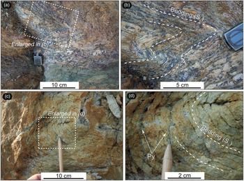
Ore lenses (pyrite, quartz and haematite, adularia, quartz) together with the greenish envelopes, made up of neoformational quartz, phlogopite and chlorite, are mimetic on the metasiliciclastic rock-texture, therefore following the geometry of both the F1 and F2 folds (Fig. 18).
Examples of ore and metasomatic lenses developed mimetically to folded S0 parallel to S1 foliation from the Valle Giove stope: (a) folded and mineralized metasandstone and (b) detail of the hinge zone; (c) folded and mineralized metasandstone and (d) detail of the hinge zone.

7. Discussion
The discussion is focused on three main issues: (a) the tectonic context in which the inherited structures formed; (b) permeability evaluation; (c) the tectonic control on the palaeo-fluid circulation and the role played by the inherited structures during the geothermal fluid flow.
7.a. Deformational events in the framework of the Elba and Northern Apennines tectonic evolution
Concerning the folding events described in the study areas, similar structures have been recognized in the metamorphic rocks exposed in the inner Northern Apennines, where two main folding events have been described by several authors (e.g. Costantini et al. Reference Costantini, Decandia, Lazzarotto and Sandrelli1988; Carmignani & Kligfield, Reference Carmignani and Kligfield1990; Conti et al. Reference Conti, Costantini, Decandia, Elter, Gattiglio, Lazzarotto, Meccheri, Pandeli, Rau, Sandrelli, Tongiorgi and Di Pisa1991; Liotta, Reference Liotta2002; Molli et al. Reference Molli, Giorgetti and Meccheri2002; Carosi et al. Reference Carosi, Iacopini and Montomoli2004; Aldinucci et al. Reference Aldinucci, Brogi and Sandrelli2005; Brogi, Reference Brogi2006; Brogi & Giorgetti, Reference Brogi and Giorgetti2012; Capezzuoli et al. Reference Capezzuoli, Spina, Brogi, Liotta, Bagnoli, Zucchi, Molli and Regoli2021). The F1 event, producing the isoclinal folds mainly recognized in the Valle Giove stope (Fig. 17e–g), is related to the stacking of the tectonic units forming the Northern Apennines during the collisional stage. S1 schistosity in fact displays the HP mineral assemblage as inferred for the Verrucano Group exposed in the Monte Giove, at the north of the Valle Giove mine (Bianco et al. Reference Bianco, Brogi, Caggianelli, Giorgetti, Liotta and Meccheri2015). Similar evidence has been described in southern Tuscany, along the Middle Tuscan Ridge (Costantini et al. Reference Costantini, Decandia, Lazzarotto and Sandrelli1988), where S1 consists of a composite tectonic foliation associated with HP assemblages (1.5–1.2 GPa and 400–350 °C; Theye et al. Reference Theye, Reinhardt, Goffé, Jolivet and Brunet1997; Brunet et al. Reference Brunet, Monié, Jolivet and Cadet2000; Rossetti et al. Reference Rossetti, Faccenna, Jolivet, Goffé and Funiciello2002) and carpholite-bearing quartz shear veins parallel to the S1 (Theye et al. Reference Theye, Reinhardt, Goffé, Jolivet and Brunet1997; Rossetti et al. Reference Rossetti, Faccenna, Jolivet, Funiciello, Tecce and Brunet1999; Brogi & Giorgetti, Reference Brogi and Giorgetti2012; Giuntoli & Viola, Reference Giuntoli and Viola2021). On Elba Island, the S1 assemblage has been dated at 19.68 ± 0.15 Ma and 20.99 ± 0.73 Ma by 40Ar/39Ar on phengite (Deino et al. Reference Deino, Keller, Minelli and Pialli1992; Ryan et al. Reference Ryan, Papeschi, Viola, Musumeci, Mazzarini, Torgersen, Sørensen and Ganerød2021) and at 19.8 ± 1.4 Ma by 40Ar/39Ar on glaucophane (Bianco et al. Reference Bianco, Godard, Halton, Brogi, Liotta and Caggianelli2019), thus ascribing an Aquitanian–early Burdigalian (at least) age to the later stage of the collisional event (Pertusati et al. Reference Pertusati, Raggi, Ricci, Duranti and Palmeri1993). Additional radiometric dates on similar assemblages obtained for the surrounding areas indicate ages between ∼27 and 25 Ma (Brunet et al. Reference Brunet, Monié, Jolivet and Cadet2000 with references therein), therefore suggesting that the F1 folds are structures deriving from a polyphase deformational event (Molli et al. Reference Molli, Conti, Giorgetti, Meccheri and Oesterling2000; Brogi & Giorgetti, Reference Brogi and Giorgetti2012) at deep structural levels. Conversely, F2 folds are asymmetric and developed at shallower structural levels, as indicated by the texture and structure of the S2 foliation. This folding event is younger than 19.68 ± 0.15 Ma and older than the age of mineralization (5.39 ± 0.46 Ma and 5.53 ± 0.14 Ma), developed during the activity of the normal faults, now dissecting the F1/F2 folds. The F2 event is interpreted as the effect of the tectonic activity ongoing during exhumation and uplift of the previously stacked tectonic pile (Carmignani & Kligflied, Reference Carmignani and Kligfield1990; Carmignani et al. Reference Carmignani, Decandia, Disperati, Fantozzi, Lazzarotto, Liotta and Meccheri1994; Montomoli et al. Reference Montomoli, Ruggieri, Boiron and Cathelineau2001; Liotta, Reference Liotta2002; Carosi et al. Reference Carosi, Iacopini and Montomoli2004).
7.b. Permeability evaluation
Suitable secondary permeability is essential for geothermal fluid flow (Rowland & Sibson, Reference Rowland and Sibson2004; Zucchi et al. Reference Zucchi, Brogi, Liotta, Rimondi, Ruggieri, Montegrossi, Caggianelli and Dini2017; Liotta et al. Reference Liotta, Brogi, Ruggieri and Zucchi2021). The method we adopted to estimate permeability (k) is based on measurement of vein length and thickness, assuming that veins with the same mineral association were contemporaneously formed, simplifying the polyphase development of the mineralized veins. This is a necessary assumption, since we deal with shear veins, where cataclasis is contemporaneous with mineral deposition, preventing the typical banded vein texture indicative of different events of crystallization (e.g. Oliver & Bons, Reference Oliver and Bons2001; Bons et al. Reference Bons, Elburg and Gomez-Rivas2012).
Nevertheless, considering the limit of the parallel plate model and the above-mentioned simplifications, the results are comparable with the permeability measured in active geothermal systems (Rowland & Sibson, Reference Rowland and Sibson2004). Moreover, taking into account that the study area can be considered as having developed in the same tectonic framework of the Larderello geothermal field (Puxeddu, Reference Puxeddu1984; Liotta et al. Reference Liotta, Brogi, Meccheri, Dini, Bianco and Ruggieri2015; Zucchi et al. Reference Zucchi, Brogi, Liotta, Rimondi, Ruggieri, Montegrossi, Caggianelli and Dini2017), it is significant that the permeability values we have obtained are in the range of those measured within the so-called first reservoir exploited in the Larderello geothermal area, at 1–2 km depth (Cappetti et al. Reference Cappetti, Parisi, Ridolfi and Stefani1995; Batini et al. Reference Batini, Brogi, Lazzarotto, Liotta and Pandeli2003; Romagnoli et al. Reference Romagnoli, Arias, Barelli, Cei and Casini2010), located at the same structural level we studied in the mining area. Another positive confirmation derives from the experimental studies conducted on fluid-assisted brittle shear zones, which provide typical values of permeability of between 10−14 and 10−16 m2 (Townend & Zoback, Reference Townend and Zoback2000; Wibberley & Shimamoto, Reference Wibberley and Shimamoto2003).
7.c. The tectonic control on the palaeo-fluid circulation
Oblique-slip to normal faults dissected the F1 and F2 folds, indicating that a brittle deformation occurred in an extensional setting and affected the previously formed contractional structures. This setting, described by several authors for the whole inner Northern Apennines (e.g. Carmignani et al. Reference Carmignani, Decandia, Disperati, Fantozzi, Lazzarotto, Liotta and Meccheri1994; Liotta et al. Reference Liotta, Cernobori and Nicolich1998; Brogi, Reference Brogi2008, Reference Brogi2020; Brogi & Liotta, Reference Brogi and Liotta2008; Molli, Reference Molli, Siegesmund, Fügenschuh and Froitzheim2008; Barchi, Reference Barchi, Beltrando, Peccerillo, Mattei, Conticelli and Doglioni2010), has also been reconstructed for Elba Island (e.g. Keller & Pialli, Reference Keller and Pialli1990; Pertusati et al. Reference Pertusati, Raggi, Ricci, Duranti and Palmeri1993; Collettini & Holdsworth, Reference Collettini and Holdsworth2004; Smith et al. Reference Smith, Holdsworth and Collettini2011; Liotta et al. Reference Liotta, Brogi, Meccheri, Dini, Bianco and Ruggieri2015; Zucchi et al. Reference Zucchi, Brogi, Liotta, Rimondi, Ruggieri, Montegrossi, Caggianelli and Dini2017; Mazzarini et al. Reference Mazzarini, Musumeci, Viola, Garofalo and Mattila2019; Zucchi, Reference Zucchi2020) where extensional tectonics interplayed with magmatism and related hydrothermalism (Dini et al. Reference Dini, Innocenti, Rocchi, Tonarini and Westerman2002; Westerman et al. Reference Westerman, Dini, Innocenti, Rocchi, Breitkreuz and Petford2004; Viti et al. Reference Viti, Brogi, Liotta, Mugnaioli, Spiess, Dini, Zucchi and Vannuccini2016). Nevertheless, this setting has been challenged by some authors who support a compressional setting active until Pliocene time, at least for Elba Island (e.g. Ryan et al. Reference Ryan, Papeschi, Viola, Musumeci, Mazzarini, Torgersen, Sørensen and Ganerød2021). We disagree with this interpretation simply because the normal faults controlling the mineralization exposed in the study areas, and particularly in the Calendozio–Topinetti localities (Fig. 2), were active during late Miocene – Zanclean time as indicated by the ages (5.39 ± 0.46 Ma: Lippolt et al. Reference Lippolt, Wernicke and Bahr1995; 5.53 ± 0.14 Ma: Wu et al. Reference Wu, Stuart, Heizler, Benvenuti and Hu2019) obtained for the syn-faulting haematite–adularia hydrothermal assemblages. This unequivocal consideration allows us to ascribe the faults controlling the geothermal fluid circulation to an extensional setting. A similar conclusion was reached, for the same areas and faults, by Mazzarini et al. (Reference Mazzarini, Musumeci, Viola, Garofalo and Mattila2019) who described an E–W extensional stress field at the time of faulting (see also Spiess et al. Reference Spiess, Langone, Caggianelli, Stuart, Zucchi, Bianco, Brogi and Liotta2022 for a discussion).
The low- and middle-angle faults were dissected by NE- and WNW-trending high-angle faults mineralized by the same hydrothermal assemblage. The concomitant circulation of the common geothermal fluid in both the low- and middle-angle normal and high-angle faults indicates that the fault systems were contemporaneously active at the time of the mineralization, reasonably increasing the secondary permeability (Debenedetti, Reference Debenedetti1952; Gilliéron, Reference Gilliéron1959; Deschamps et al. Reference Deschamps, Dagallier, Macaudier, Marignac, Maine and Saupé1983; Mazzarini et al. Reference Mazzarini, Musumeci, Viola, Garofalo and Mattila2019). In this view, the coexistence of all the faults should be explained in the same kinematic framework, as illustrated in Figure 11, from which a W–E extensional direction is derived.
However, as already described, the same mineralization, in addition to fault damage zones, also took place in strata-bound bodies. The temperature of the mineralizing fluids is >310 °C (Deschamps et al. Reference Deschamps, Dagallier, Macaudier, Marignac, Maine and Saupé1983) and, coupled with Pb isotopic data (Lattanzi et al. Reference Lattanzi, Benvenuti, Gale, Hansmann, Köppel and Stos-Gale1997), converges towards a deep interaction with fluids of a magmatic origin (Tanelli et al. Reference Tanelli, Benvenuti, Costagliola, Dini, Lattanzi, Manieri, Mascaro and Ruggieri2001; Orlando et al. Reference Orlando, Ruggieri, Chiarantini, Montegrossi and Rimondi2017). It implies that the secondary permeability related to the fault zones played a role in channelling deep fluids. This is favoured when the fault kinematics range from strike- to oblique-slip, since fluids are preferentially channelled along the intermediate stress axis (Sibson, Reference Sibson2000).
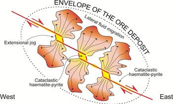
Our kinematic database indicates that the strike- to oblique-slip faults are WNW- and NE-trending (Fig. 11). The WNW-trend is also the orientation of the elliptic wrapping of the Fe-ore body exposed in the Valle Giove stope (Fig. 3). We note that in the central part of the mining area, along the WNW-trend, cataclastic mineralization occurs in discontinuous sectors. This framework accounts for extensional jogs developed in the linkage zone of WNW-trending fault segments. Deep fluids flowed up through these extensional jogs, laterally permeating the suitable lithotypes and triggering selective metasomatic processes within quartz-metasandstone and metaconglomerate (Fig. 19). The lateral migration was reasonably supported by repeated episodes of veining and circulation of fluids occasionally overpressured, as testified to by zones affected by hydrofracturing (cf. also Mazzarini et al. Reference Mazzarini, Musumeci, Viola, Garofalo and Mattila2019). Thus, the fluids permeating within the quartz-rich rocks, being confined at the top and bottom by impervious metapelite levels, reacted with the silica (Deschamps et al. Reference Deschamps, Dagallier, Macaudier, Marignac, Maine and Saupé1983), promoting metasomatic processes followed by the deposition of Fe-oxides (magnetite and haematite) and Fe-sulphide (pyrite), strongly depending on the fluid chemical–physical features, i.e. temperature, redox capacity and pH value (Anderson & Burnham, Reference Anderson and Burnham1965; Sommerfeld, Reference Sommerfeld1967; Fournier et al. Reference Fournier, Rosenbauer and Bischoff1982; Manning, Reference Manning1994; Shmulovich et al. Reference Shmulovich, Yardley and Graham2006).
Conceptual model showing the geothermal fluid migration and related ore body development reconstructed for the Valle Giove stope: the deep fluids flowed up through extensional jogs formed in the realizing step-over zone of WNW-trending faults; these fluids laterally permeated in suitable lithotypes and produced selective metasomatic processes especially within quartz-metasandstone and metaconglomerate.

This process leads to metres-thick strata-bound bodies (Zuffardi, Reference Zuffardi1990) having a geometry shaped by the F1 and F2 folding events. Consequently, the interpretation should be abandoned that the apparently folded strata-bound bodies are related to a syn-diagenetic/hydrothermal or metamorphic origin (Bodechtel, Reference Bodechtel1965; Cortecci et al. Reference Cortecci, Lattanzi and Tanelli1985; Zuffardi, Reference Zuffardi1990; Lattanzi et al. Reference Lattanzi, Benvenuti, Costagliola and Tanelli1994) responsible for a concentration of metals formerly deposited in a sedimentary/hydrothermal setting during Palaeozoic and Triassic times (see also Tanelli et al. Reference Tanelli, Benvenuti, Costagliola, Dini, Lattanzi, Manieri, Mascaro and Ruggieri2001 for a discussion).
8. Conclusions
This study allows us to define a conceptual model for the circulation of geothermal fluids in relation to inherited structures, controlling the lateral migration of fluid flow. The results have been obtained through the integration of data revealing the origin of the inherited structures with those describing the distribution of the fault zones channelling the deep fluids and their permeability. In this framework, kinematics played a key role, favouring the development of extensional jogs along the WNW-trending faults characterizing the study areas. Such jogs acted as feeder conduits from which geothermal fluids permeated the hydraulically connected siliciclastic rock bodies. When the latter were involved in previous deformational events, the fluid flow (i.e. mineralization) follows the already defined geometry, thus appearing as mineralized folds (Fig. 20). Miocene extensional tectonics determined the development of low- and middle-angle normal faults and associated minor structures (Fig. 20a); these acted even during the late Miocene mineralizing event together with the transfer faults along which fluids were channelled (Fig. 20b). The contemporaneity between the low- and middle-angle normal faults and high-angle faults (transfer zone, oblique-slip to normal faults) is testified to by the common hydrothermal mineral assemblage developed in their respective cataclasites (Fig. 20b).
Conceptual model illustrating the relationships between low- and middle-angle normal faults and high-angle faults related to the transfer zone affecting eastern Elba Island (Liotta et al. Reference Liotta, Brogi, Meccheri, Dini, Bianco and Ruggieri2015; Spiess et al. Reference Spiess, Langone, Caggianelli, Stuart, Zucchi, Bianco, Brogi and Liotta2021) and the palaeo-geothermal fluid pathway in the whole study area. Geothermal fluids accompanied the activity of the faults at 5.5 Ma (Lippolt et al. Reference Lippolt, Wernicke and Bahr1995; Wu et al. Reference Wu, Stuart, Heizler, Benvenuti and Hu2019). (a) Low- and middle-angle normal faults affected the Palaeozoic - Triassic metasiliciclastic rocks from Miocene time. (b) In a subsequent stage, high-angle faults were dominantly activated as normal faults, crosscutting previous developed structures.

Acknowledgements
The research leading to these results has received funding from the European Community’s Seventh Framework Programme under grant agreement No. 608553 (Project IMAGE). Martina Zucchi received funding also from the Italian Ministry of University and Research (MIUR), through the program PON-AIM (Attraction and International Mobility) – project no. 1815472, Activity 1, line 1.
We are indebted to our friend and colleague Marco Meccheri, who prematurely passed away, for his deep contribution during data collection and fruitful discussions in the field on the structural setting of the study areas. This paper is dedicated to him, to his memory, and to his passion for geology. We are grateful to the mining park ‘Parco Minerario of the Elba Island s.r.l.’ (https://parcominelba.it), headquartered in Rio Marina, and in particular to Marco Lunghi, for granting us permission to access the mining areas and for his continuous assistance.
We also thank ARPA-Umbria, in person of Dott.ssa Rosalba Padula, for the use of the analytical equipment at the ‘Area Dipartimentale Umbria Nord Centro Polvese cambiamento climatico e biodiversità in ambienti lacustri e aree umide’ hosted on Polvese Island, Trasimeno Lake. We are grateful to two anonymous reviewers who both helped us to improve the original manuscript with their constructive comments and suggestions.