1. Introduction
Gravity compensation refers to the use of specialized mechanisms to counteract the gravitational torque acting on an object, thereby reducing unnecessary energy consumption [Reference French and Widden1–Reference Kim, Moon, Kim and Lee3]. Over the past decades, this technique has been extensively studied and applied in various robotic and mechatronic systems. For instance, incorporating gravity compensation into the design of manipulators can significantly reduce the power demand on actuators [Reference Kim and Song4–Reference Juang, Jhuang and Chen6]. In rehabilitation exoskeletons, gravity compensation helps balance the gravitational torque on the wearer’s upper or lower limbs, facilitating movement and easing rehabilitation training [Reference Peng, Bu and Chen7–Reference Zhan, Zhang, Hou, Kang, Dai and Song9]. Similarly, surgical robots designed with integrated GCMs exhibit reduced torque requirements, enhancing precision and efficiency during operations [Reference Aldanmaz, Ayit, Kiper and Dede10].
Generally, the motion characteristics of the object being balanced remain unaltered when gravity compensation is applied [Reference Schneegans, De Jong, Cosandier and Henein11]. In certain cases, however, a synchronous relationship exists between the compensation mechanism and the moving part. For instance, the gravity compensation module often rotates at the same speed as the joints of manipulators. Consequently, if the motion characteristics can be amplified through specific design of the compensation module, the compensation performance can be enhanced beyond that of conventional designs.
GCMs can be categorized into active and passive types, depending on whether external power sources are utilized. Active GCMs generate the required compensation torque through actuators such as motors, pneumatic cylinders, or hydraulic cylinders, while passive ones rely on energy storage elements to achieve gravity compensation [Reference Kim, Moon, Ryu and Lee12–Reference Kang, Yun, Seo, Joe, Yi and Lee16]. Fundamentally, gravity compensation involves the conversion of potential energy, irrespective of the mechanism type. This study focuses on passive GCMs. Spring is a commonly used energy storage element, which has been widely adopted in various mechanical systems [Reference Kuo and Wu17]. In mechanisms employing springs, gravity compensation is typically achieved via cable-pulley units [Reference Arezoo, Arezoo, Tarvirdizadeh and Alipour18, Reference Wang, Chen, Togo, Yokoi and Jiang19], crank-rocker units [Reference Yamada and Morita20], or linkage mechanisms [Reference Kuo21].
GCMs based on cable-pulley units have been extensively studied. For instance, gravity compensation using such units can be achieved by mounting the spring either on the base or directly on the link to be compensated [Reference Morita, Kuribara, Shiozawa and Sugano22]. Liu et al. [Reference Liu, Chen and Gao23] designed an adaptive GCM for a 6 degrees of freedom (DOF) manipulator, enabling adaptation to variable payloads by adjusting the position of the spring anchor point. Arezoo et al. [Reference Arezoo, Arezoo and Fard24] proposed a GCM with a symmetrically arranged cable-pulley unit and analyzed both the static and dynamic behaviors of the system. Similarly, a reconfigurable constant-force compensation mechanism for wearable exoskeletons was presented in ref. [Reference Li, Liu, Chen, Yang and Bai25], along with a gravity compensation module capable of varying spring stiffness. Lee et al. [Reference Lee and Seo26] introduced a novel movable-pulley compensation mechanism for multi-DOF manipulators, in which performance was enhanced by strategically displacing the movable pulleys. Shi et al. [Reference Shi, Yang, Tong, Hou and Yu27] developed a cable-driven GCM incorporating both fixed and movable pulleys and evaluated the system performance through cable tension measurements. In ref. [Reference Dezman, Asfour, Ude and Gams28], a cable-driven upper limb exoskeleton was proposed, with primary focus on the effects of mechanical design and friction arising from cable-pulley contact. Alamdari et al. [Reference Alamdari, Haghighi and Krovi29] presented a static compensation mechanism for a lower limb rehabilitation exoskeleton to balance gravitational torque and validated the mechanism’s effectiveness via simulation.
The aforementioned studies on GCMs are based on cable-pulley units, and some of them have also achieved compact designs [Reference Arezoo, Arezoo and Fard24–Reference Shi, Yang, Tong, Hou and Yu27]. However, their works focus on the design of GCMs, without investigating the compact arrangement of cables or developing a systematic design methodology. In order to address the limitations of existing research, this study proposes a design method for the compact arrangement of cables. In fact, the compact cable arrangement design in this study is not merely visual but also achieves a multiple amplification of spring elongation while ensuring compactness. The advantage of GCMs employing cable multiple amplification is that, if springs with the same stiffness are used, a larger mass can be balanced. Conversely, if the same mass is to be balanced, spring with a smaller stiffness can be employed. In summary, although numerous GCMs have been developed, improvements in performance through more rational configurations and more compact structures have not been sufficiently considered.
Additionally, to simplify modeling, most existing studies treat pulleys as mass points, neglecting their potential impact on system performance. The influence of pulley size and positioning on spring elongation has not been thoroughly investigated. In reality, the contact area between the cable and pulleys varies during the mechanism’s motion. Thus, it is essential to analyze the influence of pulleys on GCMs by establishing a reasonable and accurate error model. Such a model can provide valuable guidance in the design of GCMs, helping to minimize errors introduced by pulley-related effects.
Gravity compensation techniques have been widely implemented in exoskeletons across various human joints. For the shoulder joint, Danaish et al. [Reference Danaish, Xu, Gao, Baig, Dong and Xu30, Reference Danaish, Xu, Baig, Dong, Gao and Xu31] developed lightweight exoskeletons that combine active and passive DOF, providing partial assistance to counteract gravitational torque during arm lifting. Niu et al. [Reference Niu, Guo, Yang, Qu, Song and Wang32] proposed a shoulder exoskeleton capable of compensating for joint misalignment, further improving wearer comfort. For the elbow joint, Yang et al. [Reference Yang, Zhang and Fu33] designed a cable-driven exoskeleton incorporating a variable stiffness actuator, enabling adaptive gravity compensation for upper limb rehabilitation. For the wrist and hand, Mathew et al. [Reference Mathew, Kishore, Sekhar, Pankaj and Sudheer34] presented a 4-DOF exoskeleton that supports wrist and hand movements. Ghaffari et al. [Reference Ghaffari, Sadedel, Moghaddam and Khouzani35] developed a modular wrist rehabilitation robot that integrates impedance control with gravity compensation to facilitate patient training. For the upper limb as a whole, Wu et al. [Reference Wu, Zheng, Zhu, Xu, Zhang and Wu36] developed a reconfigurable 7-DOF exoskeleton that combines gravity compensation with dynamic movement priming for rehabilitation purposes. Meng et al. [Reference Meng and Chou37] proposed a wearable arm exoskeleton for teleoperation, where a model-data fusion approach is employed to achieve gravity compensation. For the waist joint, Yang et al. [Reference Yang, Li, Li, Zhou and Wang38] developed a novel unpowered exoskeleton featuring a rigid-flexible coupled structure, with a design inspired by biomimetic cooperation to enhance kinematic compatibility and load-bearing capacity. For the lower limb, Chen et al. [Reference Chen, Shi, Zhang and Song39] designed a passive gravity compensation mechanism (GCM) for a bilateral lower limb exoskeleton, effectively reducing muscle effort during walking. For the ankle joint, Xu et al. [Reference Xu, Tang, Xu and Ding40] developed a passive exoskeleton that stores energy during dorsiflexion and releases it as assistive torque during plantarflexion, reducing calf muscle activity during walking. Beyond joint-specific rehabilitation, gravity compensation has also been applied in specialized scenarios. Jang et al. [Reference Jang, Nho and Park41] developed a gravity compensation device to reduce physical workload for indirect live-line workers. Shi et al. [Reference Shi, Chen, Zhang, Yan, Zhu and Song42] proposed a floating prosthesis concept, enabling passive gravity compensation for transradial amputees through a wearable exoskeleton design.
The torque output by exoskeletons can reduce the activation levels of muscles, thereby lowering the risk of injuries, especially for individuals who carry out repetitive tasks in their workplaces. Therefore, assistive exoskeletons have been widely employed in many industries [Reference Qu, Wang, Tang, Liu, Hao, Zhang, Liu and Cheng43]. Among them, waist exoskeletons can help mitigate the risk of low back pain – a common health issue that often results from long-term excessive pressure on the spine [Reference Huang, Guo and Zhai44]. As shown in Figure 1, during trunk flexion, the upper body can be modeled as a rigid link pivoting about the L5/S1 joint. The center of mass of the upper body is located distally from the joint, forming a long resistance arm d
r
, whereas the attachment points of the erector spinae muscles lie close to the joint, resulting in an extremely short effort arm d
e
. Consequently, the gravitational force m
up
g (where m
up
denotes the mass of the upper body) generates a gravitational moment M
up
 $=$
m
up
g · d
r
about the L5/S1 joint. To maintain equilibrium, the erector spinae muscles must produce a force F
esm
, generating a counteracting moment M
esm
 $=$
F
esm
· d
e
. Owing to the unfavorable lever ratio (i.e., d
r
≫ d
e
), the required muscle force F
esm
must be several times the upper body weight, imposing excessive mechanical loading on the lumbar spine. Prolonged exposure to such a mechanical disadvantage may lead to intervertebral disc degeneration or herniation, chronic strain of the erector spinae, and an increased risk of shear-induced lumbar spondylolisthesis.
Principle of spinal load reduction by waist exoskeleton during trunk flexion.

Figure 1. Long description
A diagram of the principle of spinal load reduction by a waist exoskeleton during trunk flexion. The diagram shows the human spine with labeled parts and forces acting on it. Key components include the erector spinae muscles, attachment points, and the L5/S1 joint acting as a fulcrum. The forces acting on the spine are labeled as F assist, F esm, m up g, M up, M exo, and M esm. The diagram illustrates the flexion and extension movements of the spine. The erector spinae muscles are shown with their origin and insertion points. The L5/S1 joint is highlighted as the fulcrum around which the moments act. The diagram explains how the exoskeleton assists in reducing the load on the spine by counteracting the gravitational torque.
In this context, the waist exoskeleton provides an external assistive force F
assist
, which generates an opposing assistive moment M
exo
about the L5/S1 joint. By sharing the gravitational load, the exoskeleton reduces the moment that must be generated by the erector spinae muscles, i.e., M
esm
 $=$
M
up
- M
exo
. Consequently, the required muscle force F
esm
is significantly decreased, mechanically unloading the spinal musculature and reducing disc compression. This biomechanical intervention effectively mitigates the risk of the aforementioned lumbar disorders.
In recent years, various waist exoskeletons have been developed. Passive waist exoskeletons (PWEs), in particular, have attracted broad interest due to their light weight, low cost, and ease of maintenance. Yang et al. [Reference Yang, Li, Li, Zhou and Wang38] developed a novel unpowered waist exoskeleton featuring a rigid-flexible coupled structure, with a design focused on enhancing kinematic compatibility and dynamic load-bearing capacity. Ding et al. [Reference Ding, Reyes, Bhattacharya, Seyram and Yu45] proposed a passive exoskeleton designed for low back pain prevention, which incorporates a spring-cable-differential mechanism. Their results indicated that the activation of the erector spinae muscles can be reduced by up to 41%. Schmalz et al. [Reference Schmalz, Colienne, Bywater, Fritzsche, Gärtner, Bellmann, Reimer and Ernst46] proposed a passive back-support exoskeleton with a spring mechanism and an automatic clutch. Their results showed that back muscle activation was reduced by up to 18%, and oxygen uptake dropped by 9% during repetitive lifting. Waist exoskeletons are wearable devices. Therefore, compact and small-sized exoskeletons are more popular because there is less possibility of human–machine interference in the workspace. In this paper, a novel PWE is presented based on the proposed X-type unit.
The main contributions of this paper are listed as follows:
-
• A novel X-type gravity compensation unit with compact structure and adjustable cable sequencing that achieves spring elongation amplification to improve compensation efficiency.
-
• A pulley-angle error model that accounts for the influence of pulley size and position is established and verified through simulations.
-
• The proposed X-type unit is implemented in a passive waist exoskeleton, and its performance is experimentally evaluated.
The remainder of this paper is structured as follows. Section 2 outlines the design methodology of the X-type unit, which employs an adjustable cable sequencing arrangement and provides a design case using a four-pulley configuration. Section 3 introduces a pulley-angle error model that accounts for the influence of pulley size and spatial arrangement within the X-type unit. Section 4 validates the proposed error model through both simulations, evaluates the performance of the presented design case, and demonstrates the application of the X-type unit in a PWEs. Section 5 discusses the main findings and limitations of this study. Section 6 concludes this work.
2. Design of X-type gravity compensation unit
2.1. Method of spring elongation amplification
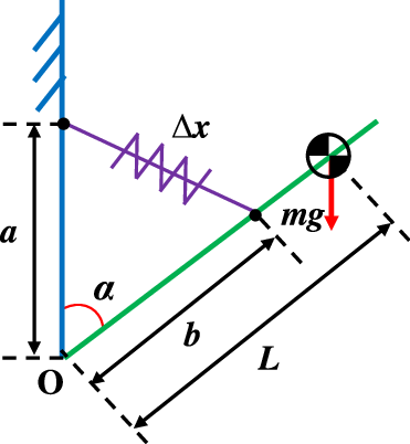
Gravity compensation fundamentally involves the conversion and conservation of potential energy. Theoretically, the total potential energy of GCMs remains constant [Reference Eckenstein and Yim47]. From this principle, the fundamental conditions for gravity compensation can be derived, which subsequently inform the design or selection of energy storage elements [Reference Morita, Kuribara, Shiozawa and Sugano22], as illustrated in Figure 2.
The traditional gravity compensation unit.

Figure 1. Long description
A diagram of the principle of spinal load reduction by a waist exoskeleton during trunk flexion. The diagram shows the human spine with labeled parts and forces acting on it. Key components include the erector spinae muscles, attachment points, and the L5/S1 joint acting as a fulcrum. The forces acting on the spine are labeled as F assist, F esm, m up g, M up, M exo, and M esm. The diagram illustrates the flexion and extension movements of the spine. The erector spinae muscles are shown with their origin and insertion points. The L5/S1 joint is highlighted as the fulcrum around which the moments act. The diagram explains how the exoskeleton assists in reducing the load on the spine by counteracting the gravitational torque.
Where m is the mass of the object to be balanced, g is gravitational acceleration, L represents the distance between the center of mass and the center of rotation, α is the rotation angle, Δx is spring elongation, while a and b represent the distances from the pulley center to the rotation center.
As previously noted, spring is one of the most commonly used energy storage elements in GCMs. In our previous work [Reference Fang, Bu and Chen48], we proposed the spring elongation method, implemented through five solutions. In this paper, we aim to systematically develop the X-type unit from concept to implementation. For better understanding, we also introduce some key equations in this paper. Now we examine the relationship between spring stiffness and elongation. By introducing a positive scaling factor, t (t
 $\gt$
1), the following conclusion can be drawn:
 \begin{equation} \frac{1}{2}k_{tra}{\unicode[Arial]{x0394}} x^{2}=\frac{1}{2}\frac{k_{tra}}{t}\left(\sqrt{t}{\unicode[Arial]{x0394}} x\right)^{2} \end{equation}
where k tra represents the spring stiffness in the traditional unit (Figure 2).
Eq. (1) indicates that if the spring elongation is multiplied by a factor of
 $\sqrt{t}$
, the stiffness will be reduced to k
tra
/t. However, if the same spring stiffness is used, the situation differs. According to the principle of conservation of potential energy:
 \begin{align} \begin{cases} \dfrac{k_{x-type}}{2}\left(\sqrt{t\left(a^{2}+b^{2}-2ab\cos \alpha \right)}\right)^{2}+m'gL\cos \alpha =V_{\textit{const}}\\ k_{x-type}=\dfrac{k_{tra}}{t}=\dfrac{mgL}{tab},m'=m\\[6pt] k_{x-type}=k_{tra}=\dfrac{mgL}{ab},m'=tm \end{cases} \end{align}
where V const represents potential energy constant. k x-type is the spring stiffness in the x-type unit, and m ′ is the mass to be compensated under determined.
If the same spring stiffness is retained, Eq. (2) shows that the mass compensable by the GCM is amplified to tm. To simplify the notation, we refer to the spring elongation amplification factor,
 $\sqrt{t}$
, as “the scale” in the following sections.
In the case where only one spring unit is used, the total spring elongation, Δx, can be expressed as the sum of several component elongations, as given by:
 \begin{equation} {\unicode[Arial]{x0394}} x'=\sqrt{t}{\unicode[Arial]{x0394}} x={\unicode[Arial]{x0394}} x\mathop{\sum }\limits_{i=1}^{n}t_{i},\left(n\in \mathrm{\mathbb{N}}\;+\right) \end{equation}
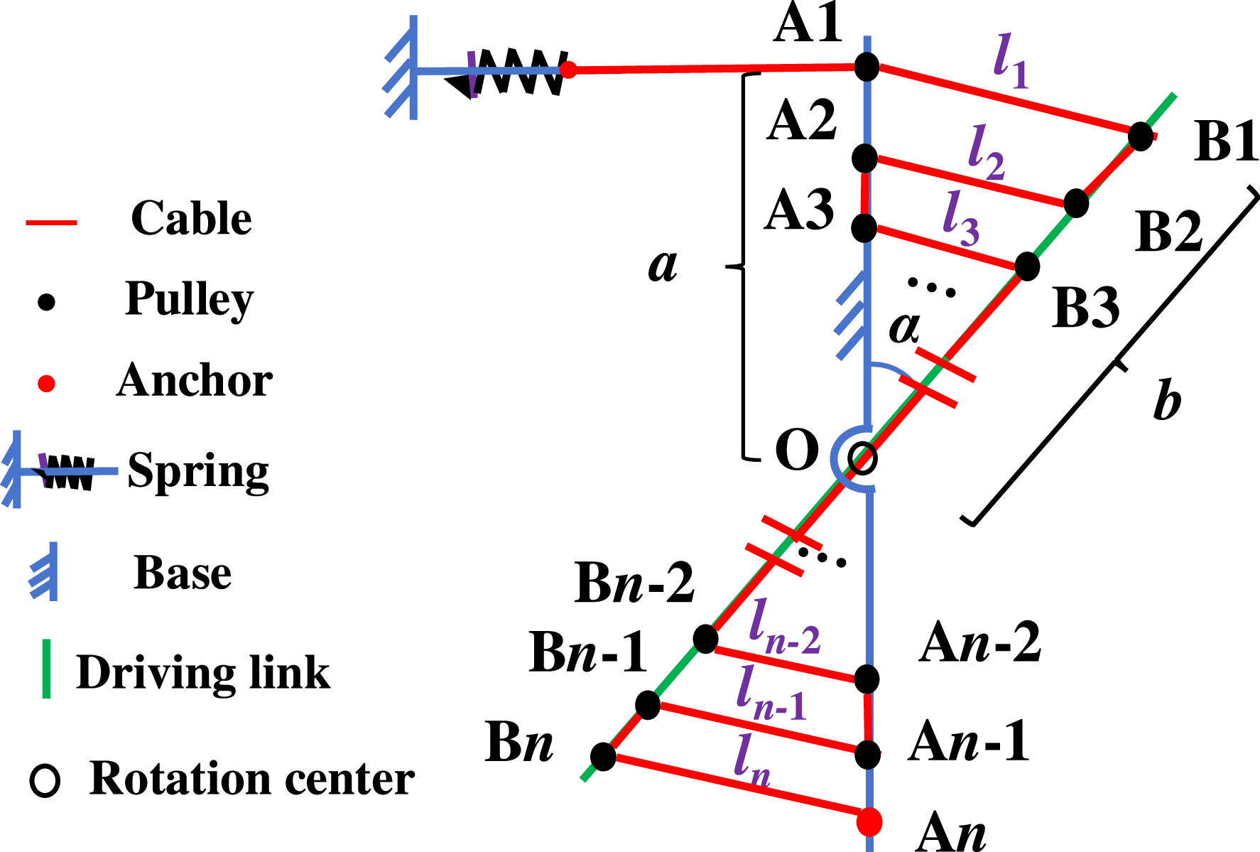
where n denotes the total number of cable segments between the base and the driving link. From Eq. (3), it is evident that each term (Δxt
i
) is proportional to Δx. Assuming that
 $l_{i},i\in [1,n]$
represents one of the cable segments, t
i
(t
i
 $\gt$
0) denotes a scaling factor that can take any positive value, then
 \begin{equation} l_{i}=t_{i}{\unicode[Arial]{x0394}} x \end{equation}
and
 \begin{equation} {\sum }_{i=1}^{n}l_{i}=\sqrt{t}{\unicode[Arial]{x0394}} x,\left(n\in \mathrm{\mathbb{N}}+\right) \end{equation}
According to Eq. (5), all segments must be parallel to each other, and their total length must equal to
 $\sqrt{t}{\unicode[Arial]{x0394}} x$
. Additionally, the motion characteristics of the object to be compensated should not be altered after the introduction of the GCM. Given that the following inequality always holds:
 \begin{equation} \frac{k_{x-type}}{2}\left(\mathop{\sum }\limits_{i=1}^{n}l_{i}\right)^{2}\neq \frac{k_{x-type}}{2}\mathop{\sum }\limits_{i=1}^{n}{l_{i}}^{2}\left(l_{i}\neq 0\right) \end{equation}
The left-hand and right-hand sides of Eq. (6) represent the elastic potential energy produced by a single spring and by multiple springs, respectively. Although the spring elongation on the left is equal to that on the right, their corresponding elastic potential energies differ, as demonstrated in Eq. (6). Thus, Eq. (6) implies that all cable segments must belong to a single continuous cable.
In summary, to achieve gravity compensation without altering the spring stiffness, the cable routing configuration must satisfy the following conditions:
-
1. The cable segments are mutually parallel, that is,
 $\mathrm{A}1\mathrm{B}1\parallel \mathrm{A}2\mathrm{B}2\parallel \cdots \parallel \mathrm{A}n-1\mathrm{B}n-1\parallel \mathrm{A}n\mathrm{B}n$
(Ai and Bi (
$i\in [1,n],n\in \mathrm{\mathbb{N}}+$
) denote the two endpoints of any segment, respectively).
-
2. All segments are part of one continuous cable, meaning a single spring produces all sub-elongations.


Based on the above analysis, simultaneous satisfaction of Condition 1 and Condition 2 leads to the implementation depicted in Figure 3.
The schematic diagram of X-type unit.

Figure 1. Long description
A diagram of the principle of spinal load reduction by a waist exoskeleton during trunk flexion. The diagram shows the human spine with labeled parts and forces acting on it. Key components include the erector spinae muscles, attachment points, and the L5/S1 joint acting as a fulcrum. The forces acting on the spine are labeled as F assist, F esm, m up g, M up, M exo, and M esm. The diagram illustrates the flexion and extension movements of the spine. The erector spinae muscles are shown with their origin and insertion points. The L5/S1 joint is highlighted as the fulcrum around which the moments act. The diagram explains how the exoskeleton assists in reducing the load on the spine by counteracting the gravitational torque.
We now discuss the relationship between a and b. When a
 $=$
b, this configuration is referred to as “the aligned configuration”. Otherwise, it is termed “the misaligned configuration”. In the former case, the actual spring elongation after scaling can still be expressed by Eq. (3), and we define
 ${\unicode[Arial]{x0394}} x_{ali}=\sqrt{t}{\unicode[Arial]{x0394}} x$
, since the initial value of l
i
is always zero. However, the situation differs in the misaligned configuration. The actual spring elongation can be expressed as:
 \begin{equation} {\unicode[Arial]{x0394}} x_{misa}=\sqrt{t}\left({\unicode[Arial]{x0394}} x-\left| a-b\right| \right) \end{equation}
The reduction in spring elongation compared to that in Eq. (3) is independent of the rotation angle and can be readily compensated by adjusting the initial elongation.
As previously defined, n is the number of cable segments. Since the X-type unit is a symmetric mechanism, n must be an even number. The number of pulleys in the X-type unit is always equal to
 \begin{equation} Num_{p}=2n,\left(n\geq 2,n\in \mathrm{\mathbb{N}}+\right) \end{equation}
2.2. The cable wrapping method using sequence
Owing to the parallel relationships among cable segments under Condition 1, the cable must be arranged in specific configurations. In this section, a cable wrapping method based on an adjustable sequence is proposed. Three approaches will be discussed in the following paragraphs.
 $\unicode{x2460}$
Cable Segments Arranged in a General Sequence
This approach requires determining the scale,
 $\sqrt{t}$
and then assigning values to t
1 ∼ t
n
according to Eq. (3). It should be noted that the relationships among cable segments are not uniquely determined.
In this approach, the factors for each cable segment are defined by the designer without violating Eq. (3). Consequently, situations where cables overlap may occur, potentially interfering with the mechanism’s motion due to friction. To avoid such issues, the following solutions are proposed.
 $\unicode{x2461}$
Cable Segments Arranged in a Geometric Sequence
Given that the X-type unit is symmetric, only one side is considered. Assume that the number of cable segments on one side is j (j
 $=$
n / 2). According to the definition of a geometric sequence, and by setting the first term c
1 equal to Δx, the following conclusion is obtained:
 \begin{equation} \frac{1-q^{\,j}}{1-q}=\frac{\sqrt{t}}{2} \end{equation}
where q denotes the common ratio of the geometric sequence.
In particular, j
 $=$
1 represents a special case in which the value of Eq. (9) becomes independent of the common ratio, i.e., t
 $=$
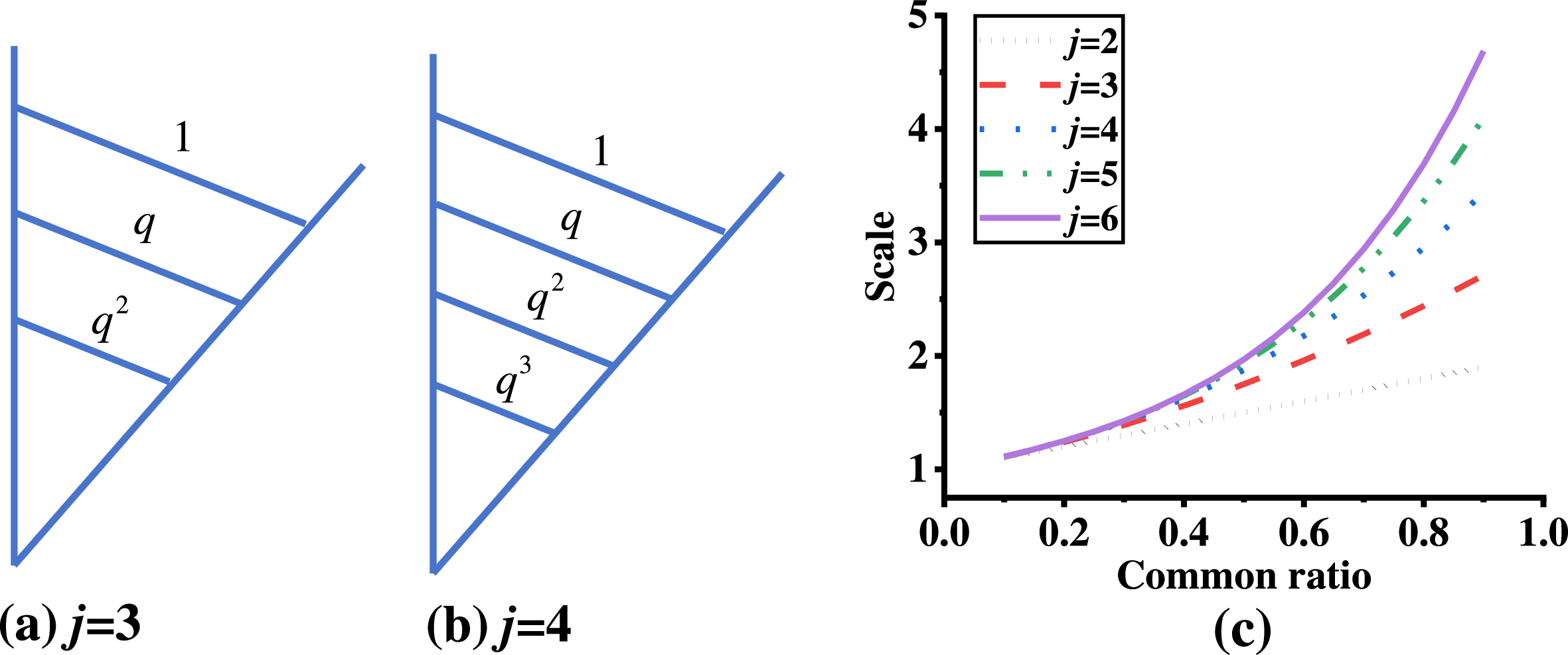
4. Figures 4(a) and (b) show the cable configurations. Figure 4(c) plots the relationships among the number of cable segments, the common ratio, and the scale. For identical common ratios, the scale increases with more segments. Conversely, for a fixed scale, fewer segments require a larger common ratio, and vice versa.
Cable configuration and parameter analysis for X-type unit with lengths following a geometric sequence. (a) and (b) Configurations of cable segments for j
 $=$
3 and j
 $=$
4. (c) Relationships among the number of cable segments, the scales, and the common ratios.

Figure 1. Long description
A diagram of the principle of spinal load reduction by a waist exoskeleton during trunk flexion. The diagram shows the human spine with labeled parts and forces acting on it. Key components include the erector spinae muscles, attachment points, and the L5/S1 joint acting as a fulcrum. The forces acting on the spine are labeled as F assist, F esm, m up g, M up, M exo, and M esm. The diagram illustrates the flexion and extension movements of the spine. The erector spinae muscles are shown with their origin and insertion points. The L5/S1 joint is highlighted as the fulcrum around which the moments act. The diagram explains how the exoskeleton assists in reducing the load on the spine by counteracting the gravitational torque.
It is evident that Eq. (9) contains three unknowns, and the third parameter can be determined only when the other two are specified. Thus, Eq. (9) suggests three distinct design approaches, namely:
-
(a) q and j are known
(10)
\begin{equation} t=\left(2\cdot \frac{1-q^{\,j}}{1-q}\right)^{2} \end{equation}
This is the simplest solution, where q and j are freely selectable from their domains.
-
(b) q and t are known
(11)
\begin{equation} j=\log _{q}\left[1-\frac{\sqrt{t}}{2}\cdot \left(1-q\right)\right] \end{equation}
The primary advantage of this approach is that the scale can be determined first. However, the number of cable segments must be an integer. Otherwise, the result lacks practical significance.
-
(c) j and t are known
(12)
\begin{equation} q^{\,j}-\frac{\sqrt{t}}{2}q+\frac{\sqrt{t}-2}{2}=0 \end{equation}
This solution essentially reduces to solving a quadratic equation. Existing research indicates that Eq. (12) is straightforward to solve when j ≤ 4, but becomes challenging to solve under j
$\gt$
4.


 $\unicode{x2462}$
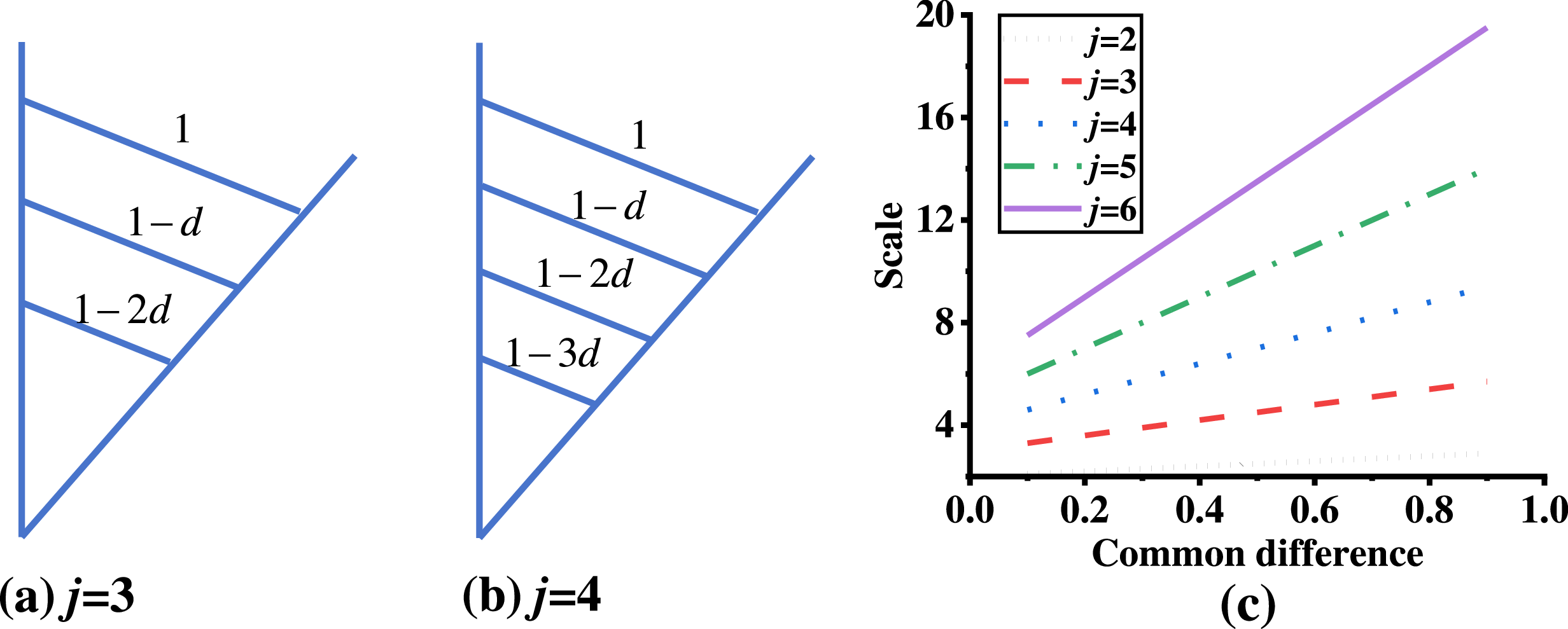
Cable Segments Arranged in an Arithmetic Sequence
The length of the first cable segment is normalized to 1. According to the definition of an arithmetic sequence, the total length of the cable segments, S, can be expressed as:
 \begin{equation} S=\left[j+\frac{j(\,j-1)}{2}d\right]{\unicode[Arial]{x0394}} x=\frac{\sqrt{t}}{2}{\unicode[Arial]{x0394}} x \end{equation}
where d represents the common difference of the arithmetic sequence.
Figures 5(a) and (b) provide a schematic diagram of the cable arrangement. The relationships among the number of cable segments, the scales, and the common differences are presented in Figure 5(c). Trends similar to those observed in the geometric sequence solution can be identified.
Cable configuration and parameter analysis for X-type unit with lengths following an arithmetic sequence. (a) and (b) Configurations of cable segments for j
 $=$
3 and j
 $=$
4. (c) Relationships among the number of cable segments, the scales, and the common difference.

Figure 1. Long description
A diagram of the principle of spinal load reduction by a waist exoskeleton during trunk flexion. The diagram shows the human spine with labeled parts and forces acting on it. Key components include the erector spinae muscles, attachment points, and the L5/S1 joint acting as a fulcrum. The forces acting on the spine are labeled as F assist, F esm, m up g, M up, M exo, and M esm. The diagram illustrates the flexion and extension movements of the spine. The erector spinae muscles are shown with their origin and insertion points. The L5/S1 joint is highlighted as the fulcrum around which the moments act. The diagram explains how the exoskeleton assists in reducing the load on the spine by counteracting the gravitational torque.
Eq. (13) indicates that designers may select any two of the following as known design parameters: the number of cable segments, the scale, or the common difference. The distinctions in parameters and problem-solving limitations among the three approaches are summarized in Table I.
Comparisons of the 3 approaches

2.3. Design case of X-type gravity compensation unit
As previously mentioned, the case where the number of cable segments on one side, j, is equal to 1 represents a special case, which can be analyzed using any of the methods summarized in Table I. In this section, the configuration corresponding to j
 $=$
1, which employs a four-pulley arrangement, is used as an example. In this configuration, t is equal to 4, indicating that the spring elongation is amplified by a factor of 2 compared to the configuration without the X-type unit.
The total number of cable segments is also equal to 2. According to the cable routing method in Section 2.2, these segments are symmetrically arranged about the center of rotation and parallel to each other, satisfying Condition 1. The cable path for this configuration is shown in Figure 6(a). Once the key parameters of the X-type unit are determined, the detailed design can be developed. As shown in Figure 6(b), the X-type unit delivers torque through the driving link, which has a complex structure. The driving link serves multiple functions, including motion transmission, cable guidance, and pulley installation. Similarly, to facilitate observation and reduce weight, Base 2 is designed as a partial enclosure rather than a complete shell, unlike Base 1.
Four-pulley configuration of the X-type gravity compensation unit. (a) Schematic diagram. (b) Structural representation.

Figure 6. Long description
Panel A: A schematic diagram of a four-pulley configuration for an X-type gravity compensation unit. The diagram includes cables, pulleys, anchors, springs, a base, a driving link, and rotation centers. The cables are connected to the pulleys, which are anchored to the base. The springs are attached to the anchors and the driving link. The driving link is connected to the rotation centers. Panel B: A structural representation of the four-pulley configuration. The structure includes a base, a driving link, a connector, and a bearing. The cables are connected to the pulleys, which are attached to the springs. The springs are connected to the driving link, which is connected to the bearing. The bearing is connected to the base.
It should be noted that the design of the X-type unit presented in this section serves as a specific illustrative example, utilizing a four-pulley configuration, to demonstrate the proposed design process in detail. Other design variations can be readily implemented by following the same methodology.
3. Error analysis with pulley size included
The spring elongation generated by the X-type unit illustrated in Figure 3 represents a theoretical value. In practice, the actual spring elongation is inevitably influenced by the size of the pulleys. Therefore, a pulley-angle error model is established in this section to quantitatively analyze the effect of pulley geometry. Given that the pulleys (anchors) are distributed on both sides – the base and the driving link – two distinct cases of pulley placement are discussed.
Case 1: The Misaligned Configuration (a ≠ b)
As shown in Figure 7(a), in this configuration, the pulleys mounted on the driving link (green circles) and those mounted on the frame (blue circles) are arranged in a misaligned manner, forming an X-type layout. The cable follows an approximately S-shaped path, exhibiting a single-sided symmetry about the rotation center O. The red solid and dashed lines indicate the cable path without and with consideration of pulley size, respectively. The notations in the figure are defined as follows: Ai and Bi denote the centers of the pulleys. Ai 1 and Bi 1 represent the first tangent points between the cable and the pulleys. Ai 2 and Bi 2 correspond to the second tangent points between the cable and the pulleys. The tangent points are sequentially defined, starting from pulley B1 and ending at pulley Bn.
The misaligned configuration of pulleys. (a) Before adjusting. (b) After adjusting.

Figure 1. Long description
A diagram of the principle of spinal load reduction by a waist exoskeleton during trunk flexion. The diagram shows the human spine with labeled parts and forces acting on it. Key components include the erector spinae muscles, attachment points, and the L5/S1 joint acting as a fulcrum. The forces acting on the spine are labeled as F assist, F esm, m up g, M up, M exo, and M esm. The diagram illustrates the flexion and extension movements of the spine. The erector spinae muscles are shown with their origin and insertion points. The L5/S1 joint is highlighted as the fulcrum around which the moments act. The diagram explains how the exoskeleton assists in reducing the load on the spine by counteracting the gravitational torque.
However, the configuration in Figure 7(a) violates the parallelism requirement stipulated by Condition 1. To resolve this issue, the pulley positions can be adjusted to ensure compliance with Condition 1, as demonstrated in Figure 7(b). This adjustment must be equal to the radius of the pulley so that the common tangent becomes parallel to the line connecting the centers of the two pulleys.
According to Eq. (8), the number of pulleys in the X-type unit is 2n. Thus, the cable length within the X-type unit for the initial and instantaneous positions of the driving link can be expressed as:
 \begin{align} l_{in}=\begin{cases} 2\left[\left(\widehat{\mathrm{A}1_{1}\mathrm{A}1_{2}}\right)_{in}+\left(\widehat{\mathrm{B}1_{1}\mathrm{B}1_{2}}\right)_{in}+\left(\overline{\mathrm{A}1\mathrm{B}1}\right)_{in}+\overline{\mathrm{A}1_{2}\mathrm{O}}\right],n=2\\ 2\left[\mathop{\sum }\limits_{i=1}^{n/2}\left[\left(\widehat{\mathrm{B}i_{1}\mathrm{B}i_{2}}\right)_{in}+\left(\widehat{\mathrm{A}i_{1}\mathrm{A}i_{2}}\right)_{in}+\left(\overline{\mathrm{A}i\mathrm{B}i}\right)_{in}+\mathop{\sum }\limits_{i=1}^{n/2-1}l_{\textit{const}\_ i}\right]+l_{\textit{tangent}2\_ O}\right],n\gt 2 \end{cases} \end{align}
 \begin{align} l_{arb}=\begin{cases} 2\left[\left(\widehat{\mathrm{A}1_{1}\mathrm{A}1_{2}}\right)_{arb}+\left(\widehat{\mathrm{B}1_{1}\mathrm{B}1_{2}}\right)_{arb}+\left(\overline{\mathrm{A}1\mathrm{B}1}\right)_{arb}+\overline{\mathrm{A}1_{2}\mathrm{O}}\right],n=2\\ 2\left[\mathop{\sum }\limits_{i=1}^{n/2}\left[\left(\widehat{\mathrm{B}i_{1}\mathrm{B}i_{2}}\right)_{arb}+\left(\widehat{\mathrm{A}i_{1}\mathrm{A}i_{2}}\right)_{arb}+\left(\overline{\mathrm{A}i\mathrm{B}i}\right)_{arb}+\mathop{\sum }\limits_{i=1}^{n/2-1}l_{\textit{const}\_ i}\right]+l_{\textit{tangent}2\_ O}\right],n\gt 2 \end{cases} \end{align}
where l
in
and l
arb
represent the actual cable lengths within the X-type unit at the initial and arbitrary positions, respectively. In Eqs. (14) and (15), all terms in parentheses with subscripts “in” and “arb” represent the cable lengths when the driving link is at the initial and arbitrary positions, respectively. For example,
 $(\widehat{\mathrm{A}1_{1}\mathrm{A}1_{2}})_{in}$
denotes the cable length between points A11 and A12 at the initial position, and
 $(\widehat{\mathrm{B}1_{1}\mathrm{B}1_{2}})_{arb}$
denotes the cable length between points B11 and B12 at an arbitrary position. l
i
indicates the length of the cable segment between pulleys mounted on different components, as illustrated in Figure 2. l
const_i
denotes the length of the cable segment between adjacent tangent points of two pulleys mounted on the same component (either the base or the driving link), which remains constant. For example,
 $l_{\textit{const}\_ 1}=\overline{\mathrm{A}1_{2}\mathrm{A}2_{1}}$
when n
 $\gt$
2, and
 $l_{\textit{const}\_ 1}=0$
when n
 $=$
2. l
tangent2_O
refers to the length of the cable segment between the second tangent point of the upper end pulley and point O.
Clearly, l in is independent of the rotation angle α. Instead, it is determined by the structure of the X-type unit – specifically, by the sizes and positions of the pulleys and the cable routing configuration. The value of larb is governed by α.
Furthermore, in the misaligned configuration, the actual spring elongation when the driving link is in an arbitrary position can be expressed as:
 \begin{equation} \left({\unicode[Arial]{x0394}} x_{act}\right)_{misa}=l_{arb}-l_{in}=2\mathop{\sum }\limits_{i=1}^{n/2}\left({\unicode[Arial]{x0394}} \widehat{\mathrm{B}i_{1}\mathrm{B}i_{2}}+{\unicode[Arial]{x0394}} \widehat{\mathrm{A}i_{1}\mathrm{A}i_{2}}+{\unicode[Arial]{x0394}} \overline{\mathrm{A}i\mathrm{B}i}\right) \end{equation}
where all Δ-terms in Eq. (16) represent the differences of the corresponding cable lengths. For example,
 ${\unicode[Arial]{x0394}} \widehat{\mathrm{B}i_{1}\mathrm{B}i_{2}}=(\widehat{\mathrm{B}i_{1}\mathrm{B}i_{2}})_{arb}-(\widehat{\mathrm{B}i_{1}\mathrm{B}i_{2}})_{in}$
.
By combining Eqs. (7) and (16), the error between the actual and theoretical spring elongation in the misaligned configuration is derived as:
 \begin{equation} (E_{th-act})_{misa}=({\unicode[Arial]{x0394}} x_{act})_{misa}-{\unicode[Arial]{x0394}} x_{misa} \end{equation}
As indicated by Eq. (17), the error model is essentially a function of the rotation angle. Moreover, the error depends on both the pulley size and the rotation angle. Additionally, it is important to note that the first and the final pulleys exhibit distinct behaviors compared to the others. The first pulley is typically connected to one end of the cable. Regarding the end pulley, the use of an auxiliary pulley can ensure that the cable length between them remains constant, thereby preventing additional spring elongation error. For example, if the rotation center of the auxiliary pulley is aligned with that of the mechanism, the relative position between the auxiliary and end pulleys remains unchanged at all times.
Case 2: The Aligned Configuration (a
 $=$
b)
In the second case, the pulleys on both sides are aligned coaxially. Figure 8(a) presents a schematic diagram of the pulley arrangement in this configuration. Compared with the first case, the cable length differs in the initial position. Additionally, if the centers of the pulleys remain on the axis of the driving link or the base, interference will occur between the pulleys on both sides in the initial position. To resolve this issue, the pulleys on both sides are moved outward such that their contours are tangent to the base and the driving link, respectively, as shown in Figure 8(b). Similarly, positional adjustment of the pulleys is necessary to maintain parallel relationships among the cable segments.
The aligned configuration of pulleys. (a) Before adjusting. (b) After adjusting.

Figure 1. Long description
A diagram of the principle of spinal load reduction by a waist exoskeleton during trunk flexion. The diagram shows the human spine with labeled parts and forces acting on it. Key components include the erector spinae muscles, attachment points, and the L5/S1 joint acting as a fulcrum. The forces acting on the spine are labeled as F assist, F esm, m up g, M up, M exo, and M esm. The diagram illustrates the flexion and extension movements of the spine. The erector spinae muscles are shown with their origin and insertion points. The L5/S1 joint is highlighted as the fulcrum around which the moments act. The diagram explains how the exoskeleton assists in reducing the load on the spine by counteracting the gravitational torque.
In the aligned configuration, it is evident that the error of the spring elongation can be described by
 $(E_{th-act})_{ali}=({\unicode[Arial]{x0394}} x_{act})_{ali}-{\unicode[Arial]{x0394}} x_{ali}$
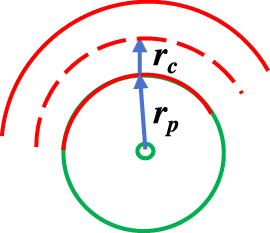
, similar to Eq. (17). However, in addition to the pulley size and rotation angle, the error in this case is also influenced by the pulley offset, with the minimum offset being equal to the radius of the pulley. Eq. (16) indicates that the spring elongation error comprises the segments between different pulleys and the arcs formed by the cable wrapping around the pulleys. The total arc length is given by the total angle multiplied by the equivalent radius of the pulley. The equivalent radius, r, as shown in Figure 9, is defined as follows:
The contact model of cable-pulley.

Figure 1. Long description
A diagram of the principle of spinal load reduction by a waist exoskeleton during trunk flexion. The diagram shows the human spine with labeled parts and forces acting on it. Key components include the erector spinae muscles, attachment points, and the L5/S1 joint acting as a fulcrum. The forces acting on the spine are labeled as F assist, F esm, m up g, M up, M exo, and M esm. The diagram illustrates the flexion and extension movements of the spine. The erector spinae muscles are shown with their origin and insertion points. The L5/S1 joint is highlighted as the fulcrum around which the moments act. The diagram explains how the exoskeleton assists in reducing the load on the spine by counteracting the gravitational torque.
 \begin{equation} r=r_{p}+r_{c} \end{equation}
where r p and r c represent the radii of the pulley and the cable cross-section, respectively.
4. Simulations and experiments
In Section 3, a pulley-angle error model was established, encompassing both aligned and misaligned configurations. This section verifies the error model through theoretical calculations and simulations. Furthermore, a testing platform was constructed to evaluate the performance of the X-type unit.
A four-pulley misaligned configuration is used as an example. Figure 10 illustrates the pulley layout and cable routing scheme, implemented according to the method proposed in Section 2.
The schematic diagram of the four-pulley configuration. (a) The misaligned configuration. (b) The aligned configuration.

Figure 1. Long description
A diagram of the principle of spinal load reduction by a waist exoskeleton during trunk flexion. The diagram shows the human spine with labeled parts and forces acting on it. Key components include the erector spinae muscles, attachment points, and the L5/S1 joint acting as a fulcrum. The forces acting on the spine are labeled as F assist, F esm, m up g, M up, M exo, and M esm. The diagram illustrates the flexion and extension movements of the spine. The erector spinae muscles are shown with their origin and insertion points. The L5/S1 joint is highlighted as the fulcrum around which the moments act. The diagram explains how the exoskeleton assists in reducing the load on the spine by counteracting the gravitational torque.
Referring to Eq. (16), the actual spring elongation in this case is given by:
 \begin{equation} \left({\unicode[Arial]{x0394}} x_{act}\right)_{misa}=2\left(\Delta \widehat{\mathrm{A}1_{1}\mathrm{A}1_{2}}+{\unicode[Arial]{x0394}} \widehat{\mathrm{B}1_{1}\mathrm{B}1_{2}}+{\unicode[Arial]{x0394}} \overline{\mathrm{A}1\mathrm{B}1}\right) \end{equation}
As previously mentioned, additional error can be avoided by fixing both ends of the cable or using an auxiliary pulley. In this case, the two ends are fixed to point O to facilitate the calculation of the actual spring elongation, as shown in Figures 10(a) and (b). The arc length can be calculated as:
 \begin{align} \begin{cases} \left(\widehat{\mathrm{A}1_{1}\mathrm{A}1_{2}}\right)_{arb}=\left[3\pi /2-\beta -\arccos \left(r/a\right)\right]\cdot r,\left(\widehat{\mathrm{A}1_{1}\mathrm{A}1_{2}}\right)_{in}=\left[3\pi /2-\pi -\arccos \left(r/a\right)\right]\cdot r\\ \left(\widehat{\mathrm{B}1_{1}\mathrm{B}1_{2}}\right)_{arb}=\left[3\pi /2-\theta -\arccos \left(r/b\right)\right]\cdot r,\left(\widehat{\mathrm{B}1_{1}\mathrm{B}1_{2}}\right)_{in}=\left[3\pi /2-\arccos \left(r/b\right)\right]\cdot r\\ \left(\overline{\mathrm{A}1\mathrm{B}1}\right)_{arb}={\unicode[Arial]{x0394}} x,\left(\overline{\mathrm{A}1\mathrm{B}1}\right)_{in}=| a-b| \end{cases} \end{align}
It should be noted that,
 $\alpha =\pi -(\beta +\theta )$
. By substituting Eq. (20) into Eq. (19), yields the spring elongation in the misaligned configuration is
 \begin{equation} ({\unicode[Arial]{x0394}} x_{act})_{misa}=2(\alpha \cdot r+{\unicode[Arial]{x0394}} x-| a-b| ) \end{equation}
Therefore, the error between the actual and the theoretical spring elongation is
 \begin{equation} (E_{th-act})_{misa}=({\unicode[Arial]{x0394}} x_{act})_{misa}-{\unicode[Arial]{x0394}} x_{misa}=2\alpha \cdot r \end{equation}
Eq. (22) indicates that the error in this case is independent of the pulley position. This conclusion will be verified through simulations.
Similarly, the spring elongation in the aligned configuration is
 \begin{equation} ({\unicode[Arial]{x0394}} x_{act})_{ali}=[2\arctan (a/r)-(\pi -\alpha ')]\cdot r+{\unicode[Arial]{x0394}} x'_{ali}-2r \end{equation}
where
 $\alpha '=\alpha +2\arctan (r/a) , {\unicode[Arial]{x0394}} x'_{ali}=\sqrt{2a'^{2}-2a'^{2}\cos \alpha '} , a'=\sqrt{a^{2}+r^{2}}$
.
The corresponding error in this configuration (t
 $=$
4 in this case) is
 \begin{equation} (E_{th-act})_{ali}=({\unicode[Arial]{x0394}} x_{act})_{ali}-2{\unicode[Arial]{x0394}} x \end{equation}
4.1. Simulations in Adams
In order to validate the proposed error model, kinematic simulations were conducted using Adams software. Based on the characteristics of the X-type unit, the position parameters of the pulleys on the base were selected as variables, while the positions of the pulleys on the driving link remained unchanged. In this configuration, the parameter b was set to 50 mm, and a varied from 20 mm to 50 mm with a step size of 10 mm. The radii of all pulleys were set to 5 mm. The motion range was set to 0° to 90°. The driving link underwent a reciprocating rotary motion, as shown in Figure 11(a).
Simulation results of the X-type mechanism with varying pulley position. (a) Velocity curve of the driving link. (b) Relationship between pulley position and spring elongation under the velocity profile in (a).

Figure 1. Long description
A diagram of the principle of spinal load reduction by a waist exoskeleton during trunk flexion. The diagram shows the human spine with labeled parts and forces acting on it. Key components include the erector spinae muscles, attachment points, and the L5/S1 joint acting as a fulcrum. The forces acting on the spine are labeled as F assist, F esm, m up g, M up, M exo, and M esm. The diagram illustrates the flexion and extension movements of the spine. The erector spinae muscles are shown with their origin and insertion points. The L5/S1 joint is highlighted as the fulcrum around which the moments act. The diagram explains how the exoskeleton assists in reducing the load on the spine by counteracting the gravitational torque.
First, the influence of different pulley positions on the spring elongation was investigated. Since the X-type unit employs only one cable, which wraps around each pulley sequentially, the actual spring elongation varies with the positions of the base pulleys. Intuitively, the closer the pulley is to point O, the smaller its contribution to the spring elongation. The simulation results confirm this conclusion, as illustrated in Figure 11(b).
The influence of pulley size was further investigated. As shown in Figures 12(a) to (d), the actual spring elongation exceeds the theoretical value due to the additional cable wrapping around the pulleys. Additionally, the magnitude of this effect varies depending on the installation positions of the pulleys. The results indicate that the spring elongation error decreases as the pulleys are positioned farther from the rotation center.
Spring elongation trends at different positions. (a) 20 mm. (b) 30 mm. (c) 40 mm. (d) 50 mm.

Figure 1. Long description
A diagram of the principle of spinal load reduction by a waist exoskeleton during trunk flexion. The diagram shows the human spine with labeled parts and forces acting on it. Key components include the erector spinae muscles, attachment points, and the L5/S1 joint acting as a fulcrum. The forces acting on the spine are labeled as F assist, F esm, m up g, M up, M exo, and M esm. The diagram illustrates the flexion and extension movements of the spine. The erector spinae muscles are shown with their origin and insertion points. The L5/S1 joint is highlighted as the fulcrum around which the moments act. The diagram explains how the exoskeleton assists in reducing the load on the spine by counteracting the gravitational torque.
Comparisons between the theoretical and simulation values are presented in Figure 12. It can be observed that the theoretical values are in close agreement with the simulation results when pulley size is taken into account, thereby validating the correctness of the proposed error model.
Furthermore, as illustrated in Figure 13(a), the theoretical results under different pulley positions are compared with the simulation data. It can be observed that, regardless of the pulley installation position, the absolute error values initially increase and then decrease within the 90° rotation range. Similar trends are evident in all other curves except for the case where the pulley is positioned at 50 mm. In general, the simulation values exceed the theoretical values due to the analogous structures of the models. However, for the pulley located at 50 mm – as noted earlier – the pulleys on both sides are offset to avoid interference. Consequently, the green curve in Figure 13(a) exhibits a distinct behavior: the simulation results are lower than the theoretical values when the rotation angle is below approximately 75°.
Analysis of pulley size effects on the X-type mechanism. (a) Comparison between theoretical and simulation results (both incorporating pulley size). (b) Comparison of theoretical results with and without pulley size inclusion.

Figure 1. Long description
A diagram of the principle of spinal load reduction by a waist exoskeleton during trunk flexion. The diagram shows the human spine with labeled parts and forces acting on it. Key components include the erector spinae muscles, attachment points, and the L5/S1 joint acting as a fulcrum. The forces acting on the spine are labeled as F assist, F esm, m up g, M up, M exo, and M esm. The diagram illustrates the flexion and extension movements of the spine. The erector spinae muscles are shown with their origin and insertion points. The L5/S1 joint is highlighted as the fulcrum around which the moments act. The diagram explains how the exoskeleton assists in reducing the load on the spine by counteracting the gravitational torque.
Additionally, the influence of pulley size on spring elongation was investigated. The errors between theoretical results with and without consideration of pulley size are presented in Figure 13(b). In the aligned configuration, the errors are smaller than those in the misaligned configuration and are independent of pulley position, thereby validating the correctness of Eq. (22).
It should be noted that the theoretical equivalent radius r was assumed equal to the simulation value to eliminate the influence of cable size. Nonetheless, a slight discrepancy between the theoretical and simulation results remains, which can be attributed to potential cable deformation during simulation; however, this error is negligible. Key error data across different pulley positions are summarized in Table II. Overall, the errors increase with the distance of the pulleys from the rotation center. For the aligned configuration, the average percentage error attributable to pulley size is 8.33%, as listed in Table III. In contrast, in the misaligned configuration, the error percentage reaches 193.45%, significantly higher than that of the aligned case. This result indicates that the influence of pulley size is significant in both configurations, particularly in the misaligned case.
The errors in different pulley positions.

The errors when pulley size is included and excluded.

The testing platform.

Figure 1. Long description
A diagram of the principle of spinal load reduction by a waist exoskeleton during trunk flexion. The diagram shows the human spine with labeled parts and forces acting on it. Key components include the erector spinae muscles, attachment points, and the L5/S1 joint acting as a fulcrum. The forces acting on the spine are labeled as F assist, F esm, m up g, M up, M exo, and M esm. The diagram illustrates the flexion and extension movements of the spine. The erector spinae muscles are shown with their origin and insertion points. The L5/S1 joint is highlighted as the fulcrum around which the moments act. The diagram explains how the exoskeleton assists in reducing the load on the spine by counteracting the gravitational torque.
4.2. Experiments
To evaluate the performance of the X-type unit, an experimental platform was constructed, as illustrated in Figure 14. A DC power supply provided stable 24 V voltage to the motor. A DC motor (24 V, transmission ratio: 139) was used to control the rotation angle of the X-type unit. A torque sensor (range: 0–10 N·m) was employed to measure the actual torque output by the motor. The pulleys were manufactured from steel, and a nylon cable was used in the experiment. The X-type unit was mounted on a frame, and a conventional PID algorithm was implemented for motor position control. All control algorithms and data acquisition were performed by an MCU. A PC was used for real-time monitoring of sensor data, logging experimental results, and sending high-level commands to the MCU. The X—type unit’s output end was fixedly attached to a mass. Its input end was connected to one side of the torque sensor, and the other side of the torque sensor was secured to the motor. The motor was installed on the frame.
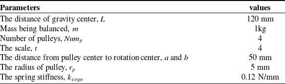
Parameters for the four-pulley configuration are provided in Table IV. It is noteworthy that, in practical applications, pulley size is always present and must be accounted for.
The parameters of the X-type unit prototype.

Based on the design of the X-type unit with four pulleys described in Section 2, a prototype was fabricated, as shown in Figure 14. Besides the pulleys required for the X-type unit, an auxiliary pulley is incorporated to redirect the cable toward the spring. Since the distance between the center of the auxiliary pulley and the rotation center remains constant, the spring elongation is not influenced by the presence of the auxiliary pulley.
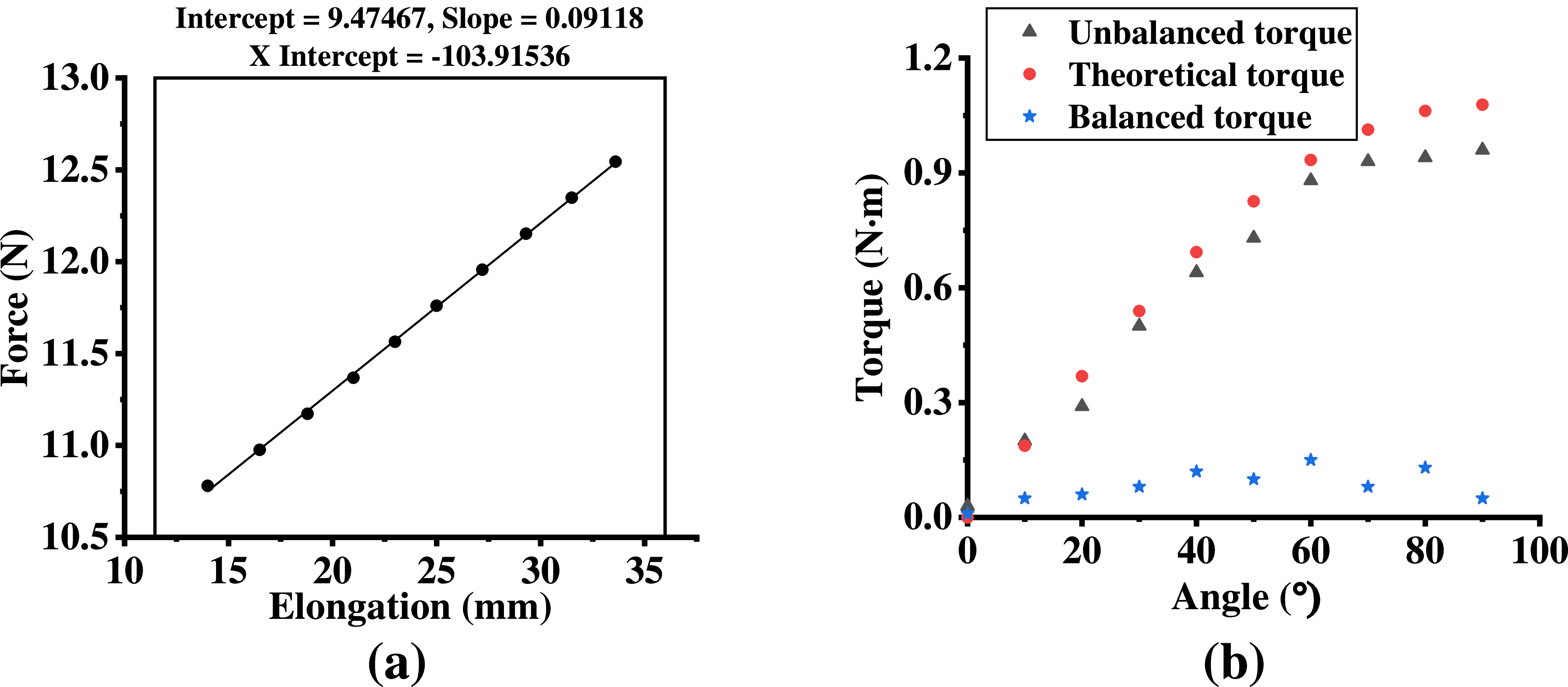
The theoretical spring stiffness can be computed using Eq. (2). However, the actual stiffness of the spring employed in the exoskeleton may differ from the theoretical value. Therefore, the actual spring stiffness was measured experimentally, as illustrated in Figure 15(a), and a linear fitting method was applied to the data.
Experimental characterization and validation of the X-type unit. (a) Measured spring stiffness. (b) Gravity compensation experimental results using the measured stiffness in (a).

Figure 1. Long description
A diagram of the principle of spinal load reduction by a waist exoskeleton during trunk flexion. The diagram shows the human spine with labeled parts and forces acting on it. Key components include the erector spinae muscles, attachment points, and the L5/S1 joint acting as a fulcrum. The forces acting on the spine are labeled as F assist, F esm, m up g, M up, M exo, and M esm. The diagram illustrates the flexion and extension movements of the spine. The erector spinae muscles are shown with their origin and insertion points. The L5/S1 joint is highlighted as the fulcrum around which the moments act. The diagram explains how the exoskeleton assists in reducing the load on the spine by counteracting the gravitational torque.
As shown in Figure 15(b), within the motion range of 0° to 90°, the torque applied to the X-type unit by the motor can be reduced, as indicated by the blue data points. These results confirm that gravity compensation is realized by the X-type unit. It should be noted, however, that the actual gravitational torque generated by the mass may deviate from the theoretical value owing to errors introduced by factors such as friction, assembly, and manufacturing.
It should be noted that the mass in this case is 1 kg, with the scale t set to 4. According to Eq. (2), if the same spring is used, only a mass of 0.25 kg could be balanced without the X-type unit.
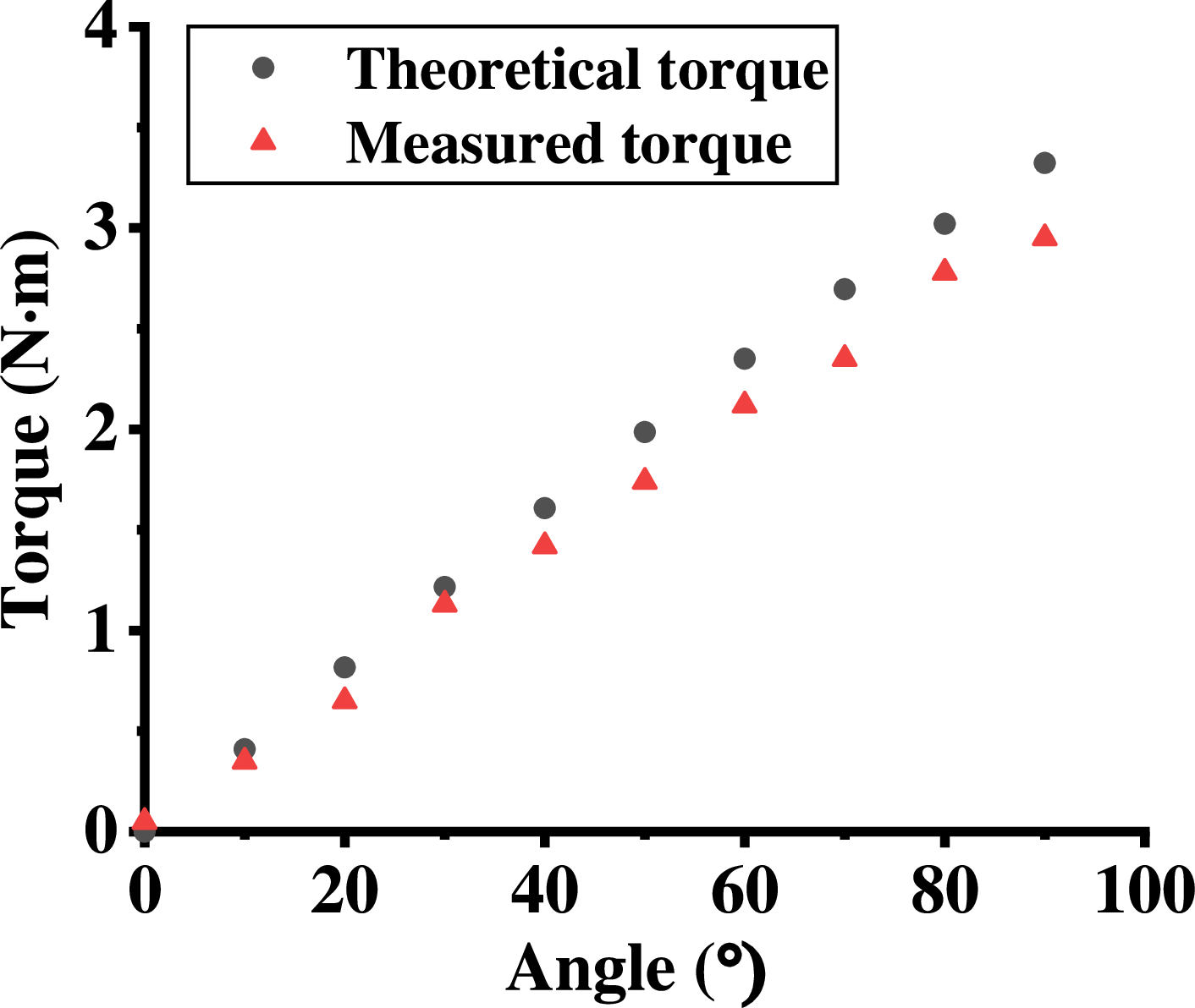
A passive waist exoskeleton incorporating the X-type unit was fabricated, as shown in Figure 16(a). The performance of the exoskeleton was then evaluated on a testing platform similar to that described earlier, but with the mass removed, as depicted in Figure 16(b). In this experiment, the output torque of the X-type unit was measured at 5° intervals with a torque sensor over a motion range of 0° to 90°. The results are presented in Figure 17, along with the corresponding theoretical torque values. Consistent with previous findings, the measured torque values are lower than the theoretical predictions. In this case, a maximum torque of 2.95 N·m was observed.
Prototype of the PWE and experimental validation. (a) PWE Prototype. (b) Output torque test of the X-type unit installed in the PWE.

Figure 1. Long description
A diagram of the principle of spinal load reduction by a waist exoskeleton during trunk flexion. The diagram shows the human spine with labeled parts and forces acting on it. Key components include the erector spinae muscles, attachment points, and the L5/S1 joint acting as a fulcrum. The forces acting on the spine are labeled as F assist, F esm, m up g, M up, M exo, and M esm. The diagram illustrates the flexion and extension movements of the spine. The erector spinae muscles are shown with their origin and insertion points. The L5/S1 joint is highlighted as the fulcrum around which the moments act. The diagram explains how the exoskeleton assists in reducing the load on the spine by counteracting the gravitational torque.
The theoretical and the measured torque generated by the PWE.

Figure 1. Long description
A diagram of the principle of spinal load reduction by a waist exoskeleton during trunk flexion. The diagram shows the human spine with labeled parts and forces acting on it. Key components include the erector spinae muscles, attachment points, and the L5/S1 joint acting as a fulcrum. The forces acting on the spine are labeled as F assist, F esm, m up g, M up, M exo, and M esm. The diagram illustrates the flexion and extension movements of the spine. The erector spinae muscles are shown with their origin and insertion points. The L5/S1 joint is highlighted as the fulcrum around which the moments act. The diagram explains how the exoskeleton assists in reducing the load on the spine by counteracting the gravitational torque.
Additionally, Figure 18 illustrates the PWE worn by the volunteer, along with demonstrations of the most common waist movements: bending and stooping.
5. Discussion
Feature comparison of PWEs.

Note: N/A
 $=$
Not applicable (i.e., the feature does not apply to this case) or not available (i.e., data not obtained).
PWE worn by volunteer. (a) Front view. (b) Side view. (c) Back view. (d) Bending. (e) Stooping.

Figure 1. Long description
A diagram of the principle of spinal load reduction by a waist exoskeleton during trunk flexion. The diagram shows the human spine with labeled parts and forces acting on it. Key components include the erector spinae muscles, attachment points, and the L5/S1 joint acting as a fulcrum. The forces acting on the spine are labeled as F assist, F esm, m up g, M up, M exo, and M esm. The diagram illustrates the flexion and extension movements of the spine. The erector spinae muscles are shown with their origin and insertion points. The L5/S1 joint is highlighted as the fulcrum around which the moments act. The diagram explains how the exoskeleton assists in reducing the load on the spine by counteracting the gravitational torque.
This study proposed a novel X-type gravity compensation unit for PWEs to address the low structural compactness and insufficient compensation efficiency of traditional cable-pulley GCMs. Centered on spring elongation amplification and adjustable cable sequencing, combined with a pulley-angle error model considering pulley size and spatial positioning, the unit’s performance was verified via simulations and physical experiments. Key findings, comparisons with existing research, engineering implications, and limitations are discussed herein.
The core achievement lies in the X-type unit’s structural realization of spring elongation amplification, which enhances compensation capacity without increasing spring stiffness. Based on potential energy conservation, the amplification scale t directly elevates the compensable mass to tm. The four-pulley configuration (t
 $=$
4) demonstrated that the same spring could balance 1 kg of mass (vs. 0.25 kg without the unit), marking a substantial improvement in compensation efficiency. This effect stems from the unit’s parallel cable segments and continuous routing, which preserve the compensated object’s motion characteristics while superimposing spring elongation. The symmetric design ensures amplification stability during link rotation, and the adjustable cable sequencing (general, geometric, arithmetic) enables flexible adaptation to diverse waist exoskeleton compensation requirements.
The established pulley-angle error model fills a critical gap in traditional cable-pulley GCM modeling, which neglects pulley size and positioning. Quantification results showed that pulley size induces non-negligible errors: 193.45% average percentage error in the misaligned configurations and 8.33% in the aligned ones. Adams simulations validated the model’s accuracy and revealed that pulley proximity to the rotation center reduces elongation and compensation contribution, with error increasing as this distance widens. This model provides a quantitative basis for pulley spatial layout in the X-type unit and other cable-pulley GCMs, enabling predictive error correction during the design phase.
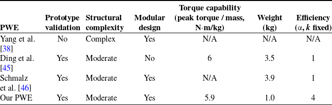
Compared with existing exoskeleton cable-pulley GCMs, the X-type unit excels in structural compactness and compensation performance. Traditional single-segment routing designs require larger installation space, increasing exoskeleton volume, and human–machine interference risks. In contrast, the X-type unit’s compact symmetric structure and multi-segment parallel cables achieve amplification without volume expansion, aligning with PWE miniaturization and lightweight requirements. For instance, as shown in Table V, while the rigid-flexible coupled PWE of Yang et al. [Reference Yang, Li, Li, Zhou and Wang38] and the spring-cable-differential PWE of Ding et al. [Reference Ding, Reyes, Bhattacharya, Seyram and Yu45] have demonstrated efficacy, they suffer from structural complexity or limited compensation efficiency. A modular design method is adopted in our PWE, enabling the entire X-type unit to be replaced for easy maintenance. Efficiency is defined as the gravity compensation efficiency of the mechanism under fixed rotational angle and spring stiffness. This metric specifically assesses whether the mechanism enables amplification of the spring elongation. In contrast to the devices reported in Refs. [Reference Ding, Reyes, Bhattacharya, Seyram and Yu45, Reference Schmalz, Colienne, Bywater, Fritzsche, Gärtner, Bellmann, Reimer and Ernst46], the proposed X-shaped unit achieves a fourfold amplification of the spring elongation. The peak torque of the designed PWE is 2.95 N·m (per side). Notably, this torque can be further increased by raising the spring stiffness. Therefore, it seems unreasonable to compare only the peak torque of different PWEs. Hence, in Table V, we adopt the ratio of peak torque to weight to evaluate the torque capability of PWEs. Additionally, its simplified structural adjustment (via cable sequencing and pulley number) is more suitable for passive exoskeletons’ low-cost, easy-maintenance design compared with adaptive GCMs for manipulators [Reference Liu, Chen and Gao23] and movable-pulley mechanisms [Reference Lee and Seo26].
Experimental verification confirmed the X-type unit’s practical engineering value. Bench tests showed significant reductions in motor torque required to drive compensated mass, directly validating gravitational torque counteraction. PWE prototype tests revealed theoretical-consistent output torque, with residual errors attributed to manufacturing inaccuracies, cable deformation, friction, and contact model deviations – common in mechanical prototypes, and addressable via precision optimization, high-strength low-deformation cables, and friction-reduction structures. Volunteer wearing demonstrations confirmed smooth waist motion without obvious human–machine interference, indicating strong application potential in industrial lifting, rehabilitation training, and other scenarios requiring lumbar assistance.
This study has several limitations. First, biomechanical validation (e.g., lumbar EMG, spinal pressure measurements) was not conducted, leaving the actual human assistance effect and posture-dependent performance unquantified. Second, research focused on static compensation, with dynamic response under rapid waist movements unstudied. Finally, the effects of manufacturing inaccuracies, cable deformation, and friction are not investigated in this paper. While the pulley-angle error model focuses on geometric errors to establish the foundational design principle, it is acknowledged that non-geometric factors such as friction and cable elasticity also contribute to performance deviations. In our experimental observations, geometric errors appear to be the primary determinant of the torque-angle trend, whereas friction acts as a secondary, load-dependent factor that primarily reduces the absolute output magnitude. Future work will focus on developing a hybrid model that incorporates empirical friction compensation into the current geometric framework.
For the design of the PWE, in particular, the waist frame that connects the X-type units has yet to undergo ergonomic optimization, and further refinement is needed to better accommodate the natural contours of the human body, thereby improving wearing comfort. Additionally, the current exoskeleton is primarily developed for functional validation and can accommodate a limited range of users. To enhance its usability and broader acceptance, further efforts are required to improve its adaptability to individual anatomical differences.
Concerning the cable-pulley-based exoskeleton proposed in this study, the main safety concerns involve the potential failure of cables and springs – a common limitation in such exoskeletons. Given the finite service life of these components, regular inspection and proactive maintenance prior to failure are essential to minimize associated safety risks.
For passive exoskeletons, proper wearing procedure is critical for safe operation. All straps must be securely fastened to prevent undesirable displacement of the exoskeleton during use. First-time users may benefit from assistance to become proficient in the donning process. Furthermore, users must be fully aware of the intended function of the exoskeleton. The proposed waist exoskeleton is designed to provide assistive torque during bending motions, thereby alleviating spinal load. Activities such as running or jumping should be avoided, as they may be impeded by the exoskeleton and could increase the risk of falls or other injuries.
In summary, the X-type GCU effectively resolves the compactness and efficiency deficiencies of traditional cable-pulley GCMs for PWEs via elongation amplification and adjustable cable sequencing. The pulley-angle error model provides a theoretical foundation for accurate GCM design. Simulations and experiments validate the unit’s performance, and the PWE prototype exhibits practical application potential. Addressing the identified limitations – multi-configuration testing, biomechanical verification, dynamic performance analysis, and lightweight design – will further advance the X-type unit’s engineering value and application scope in passive waist exoskeletons.
6. Conclusions
To address the issues of large size and insufficient compactness in existing GCMs, this paper proposes a novel X-type gravity compensation unit. A cable routing method with an adjustable sequence is specifically introduced. The X-type unit is designed to amplify spring elongation, implying that, for a given spring stiffness, the compensated mass can be increased by the same scale. As a result, the performance of the GCM is enhanced. Moreover, the compactness and overall size of the GCM are improved through the unique structural design of the X-type unit and its associated cable routing strategy.
Owing to the specific cable wrapping path, the span of the cable between pulleys varies with their positions within the X-type unit. Therefore, this paper analyzes the influence of pulley positions on spring elongation. The results indicate that spring elongation decreases as the pulleys are placed closer to the rotation center. On the other hand, pulley size is another critical factor, particularly in mechanisms employing multiple pulleys. This observation is supported by comparisons between results obtained with and without considering pulley size. A design case demonstrates average error percentages of 193.45% and 8.33% in the misaligned and aligned configurations, respectively.
To quantitatively analyze the influence of pulley size, a pulley-angle error model is established and validated using Adams software. A testing platform was subsequently constructed to evaluate the performance of the X-type unit in a four-pulley configuration, as designed in Section 2. Experimental results confirm that the proposed design achieves effective gravity compensation. The primary sources of residual error include manufacturing inaccuracies, cable deformation, friction, and discrepancies between the theoretical and actual cable-pulley contact models.
As an example of practical application, a PWEs based on the four-pulley X-type unit was developed. The output torque was measured on the testing platform, reaching a maximum of 2.95 N·m within a 0° to 90° motion range. It should be noted that the maximum or average output torque of the exoskeleton is design-dependent. For instance, the torque output can be increased by increasing the parameter a (the distance from the first pulley center to the rotation center). This study focuses on the design methodology of the X-type unit and its potential applications.
Finally, it is important to emphasize that the mathematical error model is a function of the rotation angle. In future work, this model will be applied to optimize the X-type unit design, thereby minimizing the influence of pulley size.
Author contributions
Laixin Fang and Wanghui Bu conceived and designed the study. Laixin Fang performed experiments. Laixin Fang, Wanghui Bu, and Jing Chen wrote the article.
Financial support
This work was supported in part by the National Natural Science Foundation of China (62527809, 51475331), and the Fundamental Research Funds for the Central Universities of China.
Conflicts of interest
The authors declare no conflicts of interest exist.
Ethical approval
Not applicable.

 =
 =
 =
 =