Nomenclature
- ACS
-
Attitude control system
- DOBPH∞C
-
Disturbance observer with H∞ control system
- LMI
-
Linear matrix inequality
- GEO
-
Geostationary orbit
- SMC
-
Sliding mode control
- PID
-
Proportional integral derivative
1.0 Introduction
In recent years, the attitude control problem of flexible structures in space has received much attention, especially the design of flexible geostationary (GEO) satellites, which carry a rigid hub and flexible components, such as solar panels and antennas. However, these flexible structural elements may affect the attitude control performance and the pointing accuracy requirements during the orbital motion. To solve this problem, various control schemes have been proposed for attitude control problems to suppress the unwanted vibration torques of the flexible appendages and improve attitude control accuracy.
Different approaches were developed to deal with the problem of attitude control and suppress flexible vibration. Among them, the classical and robust optimal PID control [Reference Orazulume and Jiya1,Reference Pukdeboon2], adaptive control [Reference Yucelen, Haddad and Johnson3,Reference Zeng, Araujo and Singh4], variable structure control [Reference Hu and Ma5,Reference Ye and Sun6]. One of the most applied methods in the attitude control system (ACS) for flexible spacecraft is sliding mode control (SMC) since it has a high degree of robustness and anti-disturbance capacity [Reference Xu, Cui, Fan and Guan7–Reference Mancini and Capello9]. However, this approach often leads to chattering due to its discontinuous switching control. In Refs (Reference Charbonnel10 and Reference Charbonnel11) a robust H∞ controller design and LMI/µ-analysis techniques have been proposed to design of flexible satellite attitude control laws. This problem is stated in the context of linear matrix inequality that provides a good disturbance rejection performance, but its usefulness for attitude stabilisation was limited. A performance comparison between a structured H∞ controller with the traditional H∞ for large flexible spacecraft have been investigated in Ref. (Reference Zhang12).
Some promising approaches to robust controllers have been realised to handle satellites’ tracking problems [Reference Zhou, Shen, Zeng and Sun13–Reference Azadi, Fazelzadeh, Eghtesad and Azadi15]. To tackle the issue of the unknown control input saturation and external disturbances, a backstepping attitude controller using an inverse tangent-based tracking function has been developed for the attitude manoeuver problem [Reference Ali, Radice and Kim16]. For this purpose, developing of attitude control techniques based on the observer of unknown inputs would be a good choice to alleviate the constraint faced by traditional feedforward control [Reference Benmansour17,Reference Li18]. A multi-objective nonlinear unknown input observer (NUIO) is investigated to achieve robust actuator fault isolation using a synthesis of H∞ methods. Nevertheless, these researches did not consider the vibrations generated by flexible dynamics.
To overcome the limitations of traditional feed-forward control and improve the performance of attitude control, an effective vibration suppression based on a disturbance observer strategy has been investigated [Reference Benmansour, Khouane and Roubache19–Reference Liu, Guo and Zhang22], which can estimate disturbances, compensate them effectively by feed-forwards, and provide robust attitude stabilisation.
Consequently, good rejection of vibrations has been made by these scholars. On the other hand, the control theories mentioned above can only be used to stabilise single or dual-axis attitude control.
The aim of this paper is to consider structural vibrations for the three-axis attitude dynamics of a flexible satellite. In contrast to previous work [Reference Souza23–Reference Eddine and Boulanouar25], a new combined disturbance observer with an H∞ control system (DOBPH∞C) is provided: an observer has been developed to estimate the disturbance and then compensate by the controller where H∞ is applied to increase system performance (robust stability and vibration suppression) in the presence of flexible appendages. The equations of motion for the three-axis attitude dynamics of a flexible spacecraft are derived. The proposed controller for attitude stabilisation is developed in the form of an LMI, and the stability of the whole system is validated by the Lyapunov method. A numerical simulation analysis is carried out to illustrate the efficiency and performance of the composed controller.
2.0 Model formulation
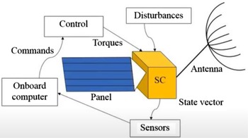
In this paper, the dynamic model of the three-axis attitude manoeuver for a spacecraft with flexible appendages under the excitation of external forces is shown in Fig. 1.
Spacecraft with flexible appendages.

The attitude dynamics equation of a rigid main body coupled with flexible appendages and other external forces can be described as follows [Reference Sidi26–Reference Wang and Li28]:
 \begin{align}J\dot \omega + {\delta ^T}\ddot \eta = u + d\end{align}
 \begin{align}{{\ddot \eta }} + 2{{\xi }}\Lambda {{\dot \eta }} + {\Lambda ^2}{{\eta }} + \delta {{\dot \omega }} = {\rm{0}}\end{align}
where
 $J$
represents the inertia matrix of the spacecraft,
 ${{\omega }}$
represents the spacecraft angular velocity in the body fixed frame,
 $\delta $
represents the coupling coefficient matrix,
 ${{\eta }}={\left[ {\begin{array}{*{20}{c}}{{\eta _1}} \cdots {{\eta _N}}\end{array}} \right]^T}$
represents the N-dimensional flexible modal coordinate,
 $\xi $
and
 $\Lambda $
represent the model ratio and the model frequency matrix, respectively,
 $u$
represents the control torque and
 $d$
represents the external bounded disturbances torque vector.
By combining (1) with (2), the model of flexible spacecraft will be
 \begin{align}({\rm{I}} - \delta {\delta ^T}){{\dot \omega }}(t) = \delta (2{{\xi }}\Lambda {{\dot \eta }} + {\Lambda ^2}{\rm{\eta }}) + {\rm{u}}(t) + {\rm{d}}(t)\end{align}
Denote
 ${\bf{\omega }} = {\left[ {\dot \varphi ,\dot \theta ,\dot \psi } \right]^T}$
,
 ${x_1} = \varphi $
,
 ${x_2} = \theta $
,
 ${x_3} = \psi $
,
 ${x_4} = \dot \varphi $
,
 ${x_5} = \dot \theta $
,
 ${x_6} = \dot \psi $
,
 ${{x}} = {\left( {{x_1},{x_2},{x_3},{x_4},{x_5},{x_6}} \right)^T}$
,
 ${\rm{u}} = {({u_x},{u_y},{u_z})^T}$
and
 ${\rm{d}} = {\left( {{d_x},{d_y},{d_z}} \right)^T}$
, then (1) and (2) can be transformed into the following form
 \begin{align}\dot{\boldsymbol{x}}(t) = {\boldsymbol{A}}{\rm{x}}(t) + {\boldsymbol{B}}({\boldsymbol{u}} + {\boldsymbol{d}} + {{\boldsymbol{d}}_{flex}})\end{align}
where
 \begin{align}{\rm{A}} = \left[ {\begin{array}{cc}{\rm{0}} &{\rm{I}}\\{\rm{0}} & {\rm{0}}\end{array}} \right]{\rm{B}} = \left[ {\begin{array}{*{20}{c}}{\rm{0}}\\{{{\left( {J - \delta {\delta ^T}} \right)}^{ - 1}}}\end{array}} \right]\end{align}
 ${d_{flex}} = \delta \left( {2\xi \Lambda \dot \eta + {\Lambda ^2}\eta } \right)$
is considered as the internal disturbance torques caused by the flexible appendage.
3.0 Composite control design
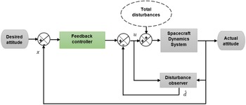
In this section, the composite control system scheme with disturbances is performed and applied to estimate feedforward compensation for the disturbances observer through flexible vibration design. The block diagram of the attitude control system is described in Fig. 2. where
 ${\hat{{\rm d}}_{flex}}$
is the estimation of the disturbance
 ${{\rm{d}}_{flex}}$
, from Fig. 2 it can be seen that the proposed controller is composed of two parts, the inner loop consists of the disturbance observer and feedforward composition, while the outside loop is the H∞ controller. Thus, the suggested controller can effectively control the flexible satellite. The vibration generated by the flexible appendages is observed and compensated, and the H∞ controller has applied to guarantee robust stability against disturbances.
Block diagram of attitude control system.

It can be derived from (1) and (2):
 \begin{align}{{\ddot \eta }}(t) = - {\Upsilon ^{ - 1}}\left[ {\delta (2{{\xi }}\Lambda {{\dot \eta }}(t) + {\Lambda ^2}{\rm{\eta }}(t)) + {\delta ^T}{{\rm{J}}^{ - 1}}({\rm{u}}(t) + {\rm{d}}(t))} \right]\end{align}
where
 \begin{align}\Upsilon = {\rm{I}} - {\delta ^T}{J^{ - 1}}\delta \end{align}
According to Ref. (Reference Guo and Cao29) the disturbance
 ${{\bf{d}}_{flex}}$
can be formulated by the following system:
 \begin{align}\left\{ {\begin{array}{l}{{{\rm{d}}_{flex}}(t) = {\rm{Vw}}(t)}\\{\dot{{\rm w}}(t) = {\rm{Ww}}(t) + {\rm{Hd}}(t)}\end{array}} \right.\end{align}
where
 \begin{align*}{\rm{w}}(t) = {\left[ {{\rm{\eta }}(t),{{\dot \eta }}(t)} \right]^T},{\rm{V}} = \delta \left[ {{\Lambda ^2},2{{\xi }}\Lambda } \right],W = \left[ {\begin{array}{c@{\quad}c}{\rm{0}}& {\bf{I}}\\{ - {\Upsilon ^{ - 1}}{\Lambda ^2}} & { - {\Upsilon ^{ - 1}}2{\bf{\xi }}\Lambda }\end{array}} \right]\,{\rm{and}}\,{\bf{H}} = \left[ {\begin{array}{*{20}{c}}{\bf{0}}\\{{\Upsilon ^{ - 1}}\delta {J^{ - 1}}}\end{array}} \right]\end{align*}
There by the disturbance observer is constructed as:
 \begin{align}\left\{ {\begin{array}{l}{{{\hat{{\rm d}}}_{flex}}(t) = {{\rm{V}}{\hat{{\rm{w}}}}}(t)}\\ \\[-7pt]{\hat{{\rm w}}(t) = {\rm{v}}(t) - {\rm{L}}x(t)}\\ \\[-7pt] {\dot{{\rm v}}(t) = ({\rm{W}} + {\rm{LBV}})({\rm{v}}(t) - {\rm{L}}x(t)) + {\rm{LA}}x(t) + {\rm{LBu}}(t)}\end{array}} \right.\end{align}
where
 $\hat{{\rm w}}(t)$
is the estimation of
 ${\rm{w}}(t)$
,
 ${\rm{v}}(t)$
is the auxiliary vector as the state of the observer,
 $L$
is the desired observer gain.
The estimation error is denoted as:
 \begin{align}{\rm{e}}(t) = {\rm{w}}(t) - \hat{{\rm w}}(t)\end{align}
Based on (4), (8), (9) and (10) it is shown that the error dynamics satisfies:
 \begin{align}\dot{{\rm e}}(t) = ({\rm{W}} + {\rm{LBV}}){\rm{e}}(t) + ({\rm{H}} + {\rm{LB}}){\rm{d}}(t)\end{align}
The purpose of rejecting disturbances can be reached by designing the observer gain such that (11) fulfils the requirement of stability and robustness performance. Thus, the structure of the proposed controller is formulated as:
 \begin{align}{\rm{u}}(t) = - {\hat{{\rm d}}_{flex}}(t) + {\rm{K}}x(t)\end{align}
Combining (4) with (12), the closed-loop system is described as:
 \begin{align}\dot x(t) = ({\rm{A}} + {\rm{BK}})x(t) + {\rm{BVe}}(t) + {\rm{Bd}}(t)\end{align}
Thus, the composite system combined (10) with (13) yields:
 \begin{align}\left[ \begin{array}{c} {\dot x(t)} \\ \\[-7pt] {\dot{{\rm e}}(t)} \end{array} \right] = \left[ \begin{array}{c@{\quad}c} {{\rm{A}} + {\rm{BK}}} & {{\rm{BV}}} \\ \\[-7pt] {\rm{0}} & {{\rm{W}} + {\rm{LBV}}} \end{array} \right]\left[ \begin{array}{c} {x(t)} \\ \\[-7pt] {{\rm{e}}(t)} \end{array} \right] + \left[ \begin{array}{c} {\rm{B}} \\ \\[-7pt] {{\rm{LB}} + {\rm{H}}} \end{array} \right]{\rm{d}}(t)\end{align}
The output of the whole system is:
 \begin{align}{\rm{z}}(t) = {{\rm{C}}_1}x(t) + {{\rm{C}}_2}{\rm{e}}(t) + {{\rm{D}}_1}{\bf{d}}(t)\end{align}
The system concerned can be defined as:
 \begin{align}\left\{ {\begin{array}{l}{\bar x(t) = \bar{{\rm A}}\bar x(t) + \bar{{\rm Bd}}(t)}\\ \\[-7pt] {{\rm{z}}(t) = {\rm{C}}\bar x + {{\rm{D}}_1}{\rm{d}}(t)}\end{array}} \right.\end{align}
where
 \begin{align*}\bar x(t) = \left[ {\begin{array}{*{20}{c}}{\dot x(t)}\\ \\[-7pt]{\dot{{\rm e}}(t)}\end{array}} \right];\,\bar{{\rm A}} = \left[ {\begin{array}{c@{\quad}c}{{\rm{A}} + {\rm{BK}}} &{{\rm{BV}}}\\ \\[-7pt]{\rm{0}} &{{\rm{W}} + {\rm{LBV}}}\end{array}} \right];\ \bar{{\rm B}} = \left[ {\begin{array}{*{20}{c}}{\rm{B}}\\ \\[-7pt]{{\rm{LB}} + {\rm{H}}}\end{array}} \right]\end{align*}
and
 $\bar{{\rm C}} = \left[ {\begin{array}{*{20}{c}}{{C_1}} {{C_2}}\end{array}} \right]$
is the weighting matrice to adjust the system performance.
With the above-mentioned equations, it can be shown that the composite system consists of two subsystems; one of which represents the error dynamical system for the estimation of the disturbance, the other results from the original system by applying the disturbance rejection strategies in control input.
The problem considered in this task is stated as follows: design an observer to estimate the disturbance, and compute a
 ${H_\infty }$
controller such as (16) is stable and satisfies
 ${\left\| {{\rm{z}}\left( t \right)} \right\|_2} \le \gamma {\left\| {{\rm{d}}\left( t \right)} \right\|_2}$
.
where
 $\gamma $
is a given positive constant.
Indeed
 ${H_\infty }$
is applied to increase system performance in the presence of both flexible appendages and external disturbances. This approach uses a linear matrix inequality (LMI) to address the control problem. LMI is a helpful tool that is directly used to find feasible and optimal solutions. The
 ${H_\infty }$
controller is an effective tool for robust stability.
3.1 Stability analysis
To ensure the robust stability of the system, the composite controller (14) is used to enhance the performance and the robustness of the whole system. For the purpose of search convenience, the following lemma is introduced:
Lemma 3.1.1 Let the state space of a generalised system is described as:
 \begin{align}\begin{array}{l}\dot{{\bf x}}(t) = G{\bf{x}}(t) + {H_{\bf{1}}}d(t) + {H_{\bf{2}}}{\bf{u}}(t)\\y(t) = {C_1}{\bf{x}}(t) + {D_{\bf{1}}}d(t) + {D_{\bf{2}}}{\bf{u}}(t)\end{array}\end{align}
where
 ${\bf{u}}(t) \in {R^m}$
the state variables of the system be measurable, the system’s state feedback controller can then be designed as:
 \begin{align}{\boldsymbol{u}}(t) = {\boldsymbol{Kx}}(t)\end{align}
 \begin{align} \begin{array}{*{20}{c}}{\dot{{\boldsymbol{x}}}(t) = ({G_1} + {H_{\bf{2}}}K){\boldsymbol{x}}(t) + {H_1}d(t)}\\{y(t) = ({C_1} + {D_{\bf{2}}}K){\boldsymbol{x}}(t) + {D_{\bf{1}}}d(t)}\end{array} \end{align}
Suppose that
 ${\rm{G }}={G_1} + {H_{\bf{2}}}K$
,
 ${\rm{H }}={{\rm{H}}_2} {\rm{C }}={C_1} + {D_{\bf{2}}}K$
and
 ${\rm{D }}={{\rm{D}}_2}$
.
Since
 $H = {\left[ {\begin{array}{*{20}{c}}{{H_1}} {{H_2}}\end{array}} \right]^T} = \left[ {\begin{array}{*{20}{c}}{\bf{0}}\\{{\Upsilon ^{ - 1}}\delta {J^{ - 1}}}\end{array}} \right]$
and
 $d(t)$
represents the external forces acting on the system, which can be much smaller compared to the vibration torques caused by the flexible appendages
 ${\boldsymbol{d}_{flex}}$
. As result, it can yield the following system.
 \begin{align}\left\{ {\begin{array}{c}{\dot x(t) = {{\rm{G}}_1}x(t) + {{\rm{H}}_2}u(t)}\\ \\[-7pt] {{\rm{y}}(t) = {{\rm{C}}_1}x(t) + {\rm{D}}{}_2u(t)}\end{array}} \right.\end{align}
For given parameters
 $\gamma \gt 0$
, if there exist,
 ${\rm{P}} \gt 0$
satisfying:
 \begin{align}\left[ {\begin{array}{c@{\quad}c@{\quad}c}{{{\rm{G}}^{\rm{T}}}{\rm{P + PG}}} & {{\rm{PH}}} &{{{\rm{C}}^{\rm{T}}}}\\ \\[-7pt]{\rm{*}} &{{\rm{ - }}{\gamma ^{\rm{2}}}{\rm{I}}} &{{{\rm{D}}^{\rm{T}}}}\\ \\[-7pt]{\rm{*}} &{\rm{*}} &{{\rm{ - I}}}\end{array}} \right] \lt 0\end{align}
Then system (20) is asymptotically stable.
Hereafter, * denotes the symmetric item in a symmetric matrix.
Proof.
Consider the Lyapunov function as follows
 \begin{align}V(t) = {x^T}(t){\rm{P}}x(t) + \int\limits_0^t {\left( {{{\rm{y}}^T}(r){\rm{y}}(r) - {\gamma ^2}{u^T}(r)u(r)} \right){\rm{d}}r \gt 0} \end{align}
where a
 ${\rm{P}} = {{\rm{P}}^T} \gt 0$
and
 $\gamma \gt 0$
is the squared
 ${H_\infty }$
norm of the transfer function matrix of the system, evaluating the derivative of
 $V(t)$
with respect to
 $t$
along a system trajectory can yields
 \begin{align}\dot V(t) = {\dot x^T}(t){\rm{P}}x(t) + {x^T}(t){\rm{P}}\dot x(t) + {{\rm{y}}^T}(t){\rm{y}}(t) - {\gamma ^2}{u^T}(t)u(t) \lt 0\end{align}
Thus, substituting system (20) into (6) gives
 \begin{align}\dot V(t) &= {\left( {{\rm{G}}x(t) + {\rm{Hd}}(t)} \right)^T}{\rm{P}}x(t)\nonumber \\[3pt] &\quad + {x^T}(t){\rm{P}}\left( {{\rm{G}}x(t) + {\rm{H}}u(t)} \right) - \gamma {\rm{d}}{u^T}(t)u(t) \nonumber\\[3pt] &\quad + {\left( {{\rm{C}}x(t) + {\rm{D}}u(t)} \right)^T}\left( {{\rm{C}}x(t) + {\rm{D}}u(t)} \right) \end{align}
with the notation below
 \begin{align}\tilde x(t) = \left[ {\begin{array}{*{20}{c}}{{x^T}(t)} {{u^T}(t)}\end{array}} \right]\end{align}
it is obtained
 \begin{align}\dot V(t) = {\tilde{x}^T}(t)\tilde {{\rm P}}\tilde x(t) \lt 0\end{align}
where
 \begin{align}\tilde{{\rm P}} = \left[ {\begin{array}{c@{\quad}c}{{{\rm{G}}^{\rm{T}}}{\rm{P}} + {\rm{PG}}} & {{\rm{PH}}}\\ \\[-7pt] * & { - {\gamma ^2}{\rm{I}}}\end{array}} \right] + \left[ {\begin{array}{c@{\quad}c}{{{\rm{C}}^{\rm{T}}}{\rm{C}}}& {{{\rm{C}}^{\rm{T}}}{\rm{D}}}\\ \\[-7pt] *& {{{\rm{D}}^{\rm{T}}}{\rm{D}}}\end{array}} \right] \lt 0\end{align}
Since
 \begin{align}\left[ {\begin{array}{c@{\quad}c}{{{\rm{C}}^{\rm{T}}}{\rm{C}}}& {{{\rm{C}}^{\rm{T}}}{\rm{D}}}\\ \\[-7pt] *& {{{\rm{D}}^{\rm{T}}}{\rm{D}}}\end{array}} \right] = \left[ {\begin{array}{*{20}{c}}{{{\rm{C}}^{\rm{T}}}}\\{{{\rm{D}}^{\rm{T}}}}\end{array}} \right]\left[ {\begin{array}{*{20}{c}}{\rm{C}} {\rm{D}}\end{array}} \right] \geqslant 0\end{align}
With Schur complement property yields
 \begin{align}\left[ {\begin{array}{c@{\quad}c@{\quad}c}{\rm{0}}& {\rm{0}} &{{{\rm{C}}^{\rm{T}}}}\\ \\[-7pt] {\rm{*}} & {\rm{0}} & {{{\rm{D}}^{\rm{T}}}}\\ \\[-7pt]{\rm{*}} &{\rm{*}} &{{\rm{ - I}}}\end{array}} \right] \geqslant 0\end{align}
Using (29) the LMI condition (27) can be written compactly as (21). This concludes the proof.
Based on Lemma 3.1.1, the following theorem can be introduced.
Theorem 3.1.2 For given parameters
 $\gamma \gt 0$
, if there exist a positive definite matrix
 ${\rm{X}} \gt 0$
,
 ${{\rm{P}}_2} \gt 0$
and matrix
 ${{\rm{R}}_{\rm{1}}}{\rm{,}}\ {{\rm{R}}_{\rm{2}}}$
satisfying the following LMI:
 \begin{align}\left[ {\begin{array}{c@{\quad}c@{\quad}c@{\quad}c}{{{\rm{M}}_1}} &{{\rm{BV}}} &{\rm{B}} &{{\rm{XC}}_1^T}\\ \\[-7pt]*& {{{\rm{M}}_2}} &{{{\rm{R}}_2}{\rm{B}} + {{\rm{P}}_2}{\rm{H}}} &{{\rm{C}}_2^T}\\ \\[-7pt]* &* &{ - {\gamma ^2}{\rm{I}}} &{{\rm{D}}_1^T}\\ \\[-7pt]*& *& *& { - {\rm{I}}}\end{array}} \right] \lt 0\end{align}
Where
 \begin{align}{{\rm{M}}_1} &= ({\rm{AX}} + {\rm{B}}{{\rm{R}}_1}) + {({\rm{AX}} + {\rm{B}}{{\rm{R}}_1})^T}\nonumber\\ \nonumber \\[-7pt]{{\rm{M}}_2} &= ({{\rm{P}}_2}{\rm{W}} + {{\rm{R}}_2}{\rm{BV}}) + {({{\rm{P}}_2}{\rm{W}} + {{\rm{R}}_2}{\rm{BV}})^T}\end{align}
Then the composite system (14) under the proposed control law (12) with gain
 ${\rm{K}} = {{\rm{R}}_1}{{\rm{X}}^{ - 1}}$
associated to the observer (9) with gain
 ${\rm{L}} = {\rm{P}}_2^{ - 1}{{\rm{R}}_2}$
is asymptotically stable and satisfies
 ${\left\| {\rm{z}} \right\|_2} \lt \gamma {\left\| {{\rm{d}}(t)} \right\|_2}.$
3.2 Proof
For the system (16), we define the matrix
 ${\rm{P}}$
as follows [Reference Wei and Guo30]:
 \begin{align}{\rm{P}} = \left[ {\begin{array}{c@{\quad}c}{{{\rm{p}}_1}}& 0\\ \\[-7pt] 0& {{{\rm{p}}_2}}\end{array}} \right] = \left[ {\begin{array}{c@{\quad}c}{{\rm{Q}}_1^{ - 1}} & 0\\ \\[-7pt] 0 & {{{\rm{P}}_2}}\end{array}} \right] \gt 0\end{align}
Applying Lemma 3.1.1 to (16), it can be verified that
 \begin{align}\left[ {\begin{array}{c@{\quad}c@{\quad}c}{{{\bar{{\rm A}}}^T}{\rm{P}} + {{\rm{P}}{\bar {{\rm A}}}}}& {{{\rm{P}}{\bar{{\rm B}}}}}& {\bar{{\rm C}}}\\ \\[-7pt]* &{ - {\gamma ^2}{\rm{I}}} &{{\rm{D}}_1^T}\\ \\[-7pt]* &* &{ - {\rm{I}}}\end{array}} \right] \lt 0\end{align}
Then
 \begin{align}\left[ {\begin{array}{c@{\quad}c@{\quad}c@{\quad}c}{{{\rm{\Pi }}_1}} & {{{\rm{P}}_{\rm{1}}}{\rm{BV}}} &{{{\rm{P}}_{\rm{1}}}{\rm{B}}}& {{\rm{C}}_1^T}\\{*} &{{{\rm{\Pi }}_2}}& {{{\rm{P}}_2}\left( {{\rm{LB}} + {\rm{H}}} \right)} &{{\rm{C}}_2^T}\\{*} & * &{ - {\gamma ^2}{\rm{I}}}&{{\rm{D}}_1^T}\\{*} &* &*& { - {\rm{I}}}\end{array}} \right] \lt 0\end{align}
where
 \begin{align}{{\rm{\Pi }}_1} &= {{\rm{P}}_1}({\rm{A}} + {\rm{BK}}) + {\left[ {{{\rm{P}}_1}\left( {{\rm{A}} + {\rm{BK}}} \right)} \right]^T}\nonumber \\[3pt] {{\bf{\Pi }}_{\bf{2}}} &= {{\bf{P}}_2}{\bf{(W}} + {\bf{LBV)}} + {\left[ {{{\bf{P}}_{\bf{2}}}\left( {{\bf{W}} + {\bf{LBV}}} \right)} \right]^{\bf{T}}}\end{align}
Pre-multiplied and post-multiplied simultaneously the LMI (34) by
 $diag\left( {{{\rm{Q}}_1},{\rm{I,I,I}}} \right),$
thus (30) can be obtained.
The next step, by defining
 ${\rm{X}} = {{\rm{Q}}_1}$
,
 ${{\rm{R}}_1} = {\rm{K}}{{\rm{Q}}_1} = {\rm{KX}}$
and
 ${{\rm{R}}_2} = {{\rm{P}}_2}{\rm{L}}$
, Consequently, by selecting the control gain as
 ${\rm{K}} = {{\rm{R}}_1}{\rm{Q}}_1^{ - 1}$
and the observer gain as
 ${\rm{L}} = {\rm{P}}_2^{ - 1}{{\rm{R}}_2}$
it can be deduced that the composite system (14) is asymptotically stable.
4.0 Simulation results
To validate the effectiveness of the designed controller, numerical simulations are performed in Matlab/Simulink environment with M.file. The proposed control scheme has been introduced to the satellite with flexible appendage while the three-axis attitude stabilisations are performed by LMI theory.
The satellite must constantly remain above a particular location on the Earth, such as a communications satellite, with an altitude of 36,000 km, whereas the orbital velocity is equivalent to the angular velocity of a normal day which is
 ${\omega _0} = 7.2921e - 5$
rad/s. The parameters of the flexible satellite are as stated below in [Reference Boulouma, Labiod and Boubertakh31].
The coupling matrix is defined as
 \begin{align*}{\rm{\delta }} = \left( \begin{array}{c@{\quad}cc@{\quad}c} 1 & {0.1}& {0.1} \\ \\[-7pt] {0.5} & {0.1} & {0.01} \\ \\[-7pt] { - 1} & {0.3}& {0.01} \end{array} \right)k{g^{1/2}}m\end{align*}
The three elastic modes are considered as
 ${\rm{\Lambda }} = diag\left\{ {0.602\pi ,1.088\pi ,1.846\pi } \right\}rad/s$
, with damping coefficients
 ${\xi _1} = {\xi _2} = {\xi _3} = 0.01$
and the modal coordinate is defined as
 $\eta = {\left[ {\begin{array}{*{20}{c}}{{\eta _1}} {{\eta _2}} {{\eta _3}}\end{array}} \right]^T}$
.
The satellite simulation parameters are listed in Table 1.
Satellite simulation parameters

Based on LMI (27), it can be solved that the controller gain
 \begin{align*}{\rm{K}} = \left[ \begin{array}{c@{\quad}c@{\quad}c@{\quad}c@{\quad}c@{\quad}c}{ - 351.774}& { - 247.970}& { - 266.156} &{ - 665.222} &{ - 154.525} &{ - 213.185}\\ \\[-7pt]{ - 264.647}& { - 303.950} &{ - 261.952} &{ - 207.086}& { - 377.452}& { - 196.160}\\ \\[-7pt]{ - 277.007}& { - 255.676} &{ - 351.767} &{ - 231.053}& { - 158.654}& { - 612.140}\end{array} \right]\end{align*}
and the observer gain
 \begin{align*}{\rm{L}} = \left[ \begin{array}{c@{\quad}c@{\quad}c@{\quad}c@{\quad}c@{\quad}c}0& 0 &0 &{ - 15.065} &{ - 21.671} &{18.295}\\ \\[-7pt]0& 0 &0 &{ - 2.718} &{ - 6.941} &{ - 10.044}\\ \\[-7pt]0& 0 &0& { - 2.507} &{ - 0.648} &{ - 0.286}\\ \\[-7pt]0& 0 &0 &{ - 0.415} &{1.286} &{1.323}\\ \\[-7pt]0& 0 &0 &{ - 2.553} &{ - 2.526} &{ - 3.669}\\ \\[-7pt]0& 0& 0 &{0.255} &{ - 1.511} &{0.609}\end{array} \right].\end{align*}
Simulation results are given as follows. The time histories of spacecraft attitude angles are shown in Fig. 3. It can be seen that the attitude stabilisation with external disturbances is successfully accomplished in 35s, a stability accuracy of 1 ×10⁻³ (deg) and 1 × 10⁻² (deg) is achieved during the time period from 50 to 80s. these results show the attitude is stabilised with high pointing accuracy compared with the classical method (state feedback controller) in the presence of external disturbance and flexible appendages.
Time responses of attitude angle.

The angular velocities of flexible spacecraft in the presence of external disturbances are given in Fig. 4. It can be observed that the angular velocities converge in 30s, and they converge more smoothly for the proposed method during steady-state operations compared with SFC method.
Time responses of attitude angle.

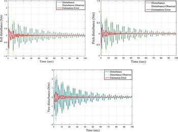
Figure 5 shows the time responses of disturbances, and estimations errors, respectively. From this, we can see that the effects of the vibrations caused by a flexible appendage and radiation torques can be reduced during attitude manoeuver. The disturbance observer is successfully employed as a tool for estimating the total disturbances in the system and preserve stability and control performance.
Time responses of disturbances along the 3-axes.

The time response of control input torque to stabilise the flexible spacecraft is presented in Fig. 6. It is apparent that the control torque eq. (12) is a little important in the beginning 5s and fastly reduced to the lowest. This means that the attitude stabilisation with high-precision can be accomplished by using the proposed control scheme for the flexible spacecraft.
Time responses of control torque.

Histogram of Attitude angles control errors using DOBPH∞C controller (a) roll axis, (b) pitch axis and (c) yaw axis and (d) global RMSE for three axes.

Histogram of Attitude angles velocity control errors using DOBPH∞C controller (a) roll axis, (b) pitch axis and (c) yaw axis and (d) global RMSE for three axes.

4.2. Monte Carlo simulation
To evaluate the performance of the planned controller, a series of Monte Carlo simulations have been carried out in Figs 7 and 8. The tests consist of 10,000 simulation runs. For each Monte-Carlo run, Euler angles and angle rates were picked randomly; the starting attitude came from a uniform population between ±10°. The attitude rates came from a uniform population between ±1°/s with a sampling of 1 and 0.1, respectively. The aim is to analyse how the accuracy performance of the method used on a flexible satellite during attitude control. In fact, for each Monte-Carlo run, the Euler angles control errors and angle rates control errors converge; moreover, the global magnitude error does not exceed 0.018(deg), for every simulation in attitude angle errors and
 ${7.10^{ - 3}}$
(deg/s) in attitude velocity errors, the Monte Carlo test confirms the performance of the proposed controller that made robust against various disturbances.
5.0 Conclusions
This paper proposed a control method to solve the problem of high-precision attitude control for three-axis stabilised flexible spacecraft. The presented composite controller scheme is adopted to reduce the total perturbation, including flexible coupling terms and external disturbances and adjust the spacecraft’s attitude. The stability and convergence of the closed-loop system are proved using the Lyapunov theory, and the linear matrix inequality technique is used to design the disturbance attitude observer and controller gains. The numerical simulations verify that the proposed method in this paper can achieve higher performance compared to a state feedback controller. Our future work will focus on practical hardware experiments.