Introduction
In 2002, the ultra-wideband (UWB) spectrum covering 3100–10,600 MHz was allocated through the US Federal Communications Commission (FCC) [Reference Kumar, Sharma, Matta, Kaur, Saluja, Malhotra, Singh, Saini and Singh1, Reference Kolangiammal, Balaji and Mahdal2]. UWB technology has attracted substantial interest. It is extensively utilized in imaging, radar, telecommunications, and other domains [Reference Ahmed3, Reference Lin, Zhongyuan, Wang and Mu4]. At the same time, channel capacity and communication quality have seen significant improvements due to the integration of MIMO technology, which achieves these enhancements without necessitating additional transmission power or frequency resources. Consequently, this has emerged as a major research focus within the field of wireless communication [Reference Ali, Munir, Nasralla, Esmail, Al-Gburi and Bhatti5–Reference Tiwari7]. Therefore, integrating MIMO with UWB technologies is essential to fully realize their advantages. UWB encompasses various narrowband networks, including WiMAX, WLAN, and X-band [Reference Agarwal, Dhanoa and Khandelwal8]. Ultra-wideband antennas incorporating integrated band-stop features are particularly effective in mitigating interference from these narrow-bandwidth signals.
The literature [Reference Kumar, Pathan, Vincent, Kumar, Yashwanth, Kumar, Shetty and Ali9–Reference Jayant and Srivastava20] explores UWB antennas with band-notch features. In reference [Reference Kumar, Pathan, Vincent, Kumar, Yashwanth, Kumar, Shetty and Ali9], decoupling is achieved through the use of additional structures on the radiator and a defected ground structure. In [Reference Babu, Ansari, Kanaujia, Singh and Kumar10], decoupling exceeding 25 dB is attained by incorporating EBG structures among the monopoles. In [Reference Weidong, Lin, Wang, Chenlu, Yang, Nie and Juan11], a T-shaped grounding branch is introduced for decoupling purposes, incorporating two refined inverted L elements and an I-shaped extension, and providing isolation exceeding 20 dB across the full operating frequency range (4.3–15.63 GHz). Reference [Reference Yang, Zhang, Xuping, Yapeng, Yang and Shi12] presents a compact ultra-wideband antenna that incorporates five band-stop features, achieved by employing three improved inverted U-patterned slots and two symmetric rectangular apertures for quintuple band-notched functionality. Reference [Reference Benghanem, Mansoul and Mouffok13] presents a novel compact dual-port MIMO antenna with dual band-notched characteristics. The antenna incorporates L-shaped and C-shaped slots in the main radiating element to effectively suppress the WLAN band and the INSAT C-band, respectively. Additionally, inverted L-shaped stubs and a wide slot are introduced in the ground plane to ensure high isolation between the two ports. In Reference [Reference Tathababu Addepalli, Mrudula Kilaru, Kamili, Kumar, Nimmagadda and Kumar14], an ultra-wideband MIMO antenna with dual band-notch characteristics is proposed. The WiMAX (3.3–3.8 GHz) and WLAN (5–6.5 GHz) notches are realized by etching hook-shaped and E-shaped stubs on the radiating patch and defective ground, respectively. The antenna in Reference [Reference Jaglan, Gupta, Thakur, Kumar, Kanaujia and Srivastava15] achieves band-rejection for the WiMAX and WLAN bands using mushroom-type Electromagnetic Band Gap (EBG) structures and for the X-band using a uniplanar cross-shaped EBG structure. Reference [Reference Luo, Wang, Chen, Ershi and Jiang16] introduces a space-efficient two-port ultra-wideband MIMO antenna demonstrating quadruple band-stop features, accomplished through the incorporation of two U-shaped apertures on the radiating element and incorporating a series of U-shaped parasitic structures on each side of the feeding lines, achieving quadruple band-stop features. Reference [Reference Modak and Khan17] demonstrates the generation of quadruple notched bands through the etching of a pair of flipped L-shaped apertures in the radiating patch and the addition of a set of mushroom-like EBG structures. In [Reference Ling, Cao, Yin, Yang and Xiaolin18], the dual-port antenna suppresses mutual coupling by cutting triangles on the upper patch, etching grounding slots, and adding dumbbell-shaped shorting pins, achieving isolation exceeding 20 dB. In [Reference Arashpreet and Kaur19], the proposed 4 × 4 MIMO antenna eliminates interference from the C-band, WLAN, as well as radio navigation bands is eliminated by merging each feed line featuring circular split-ring resonant elements, U-shaped apertures, and rectangular ring resonant elements, respectively. Reference [Reference Jayant and Srivastava20] presents a four-port MIMO antenna featuring triple notch bands. Interference from WLAN and X-band frequencies is mitigated through engraving a pair of C-shaped apertures on every radiator, while WiMAX interference is effectively mitigated by the incorporation of an L-shaped slot on the underlying plane of the substrate. In summary, the existing antennas do not effectively filter more multiple frequency bands under four-port MIMO conditions in UWB applications. Thus, developing an antenna with MIMO capabilities and multiple notch characteristics is essential.
This work introduces a four-port UWB-MIMO antenna with slot elements produced on a Rogers RT/duroid 5880 (tm) substrate, featuring penta-notched frequency bands. The antenna elements are configured in a vertical alignment and incorporate cross-shaped branches to improve isolation. The antenna delivers a −10 dB bandwidth covering the frequency range from 2.7 GHz to 11.67 GHz (125%) and can suppress signals from WiMAX (3.3–3.7 GHz), N79 (4.8–4.9 GHz), WLAN downlink (5.725–5.825 GHz), ITU-R (8.275–8.5 GHz), and Ku-Band downlink (10.7–11.2 GHz). The dimensions of the notch structure allow for independent adjustment of each notch’s central frequency. The antenna exhibits ECC below 0.04 and provides isolation superior to 20 dB. Experimental results demonstrate the antenna’s good impedance and band-notched characteristics.
The innovations of the antenna are as follows: (1) The antenna is designed as a four-port MIMO antenna, further enhancing the capacity and spectrum utilization of the communication system. (2) The antenna features quintuple band-notch capabilities, capable of filtering signals from WiMAX (3.3–3.7 GHz), the N79 band (4.8–4.9 GHz), WLAN downlink (5.725–5.825 GHz), the ITU-R band (8.275–8.5 GHz), and the Ku-band downlink (10.7–11.2 GHz). Furthermore, each band-notch can be independently adjusted. (3) The antenna has a wide bandwidth, enabling full coverage of the ultra-wideband frequency range, with a relative bandwidth of 125%. (4) The antenna features a connected ground design, achieving a high isolation greater than 20 dB, an Envelope Correlation Coefficient (ECC) of less than 0.04, and a Diversity Gain (DG) exceeding 9.995, demonstrating outstanding diversity performance. (5) The antenna employs an asymmetric C-shaped stub to realize the band-notch function, offering enhanced flexibility in notch design.
Antenna design
Single element antenna
The geometrical details of the single-element antenna are shown in Fig. 1(a), and Fig. 1(b) displays the S11 and VSWR measurement of the antenna. The antenna design is inspired by the structure presented in reference [Reference Sadineni and Gowda21], with additional optimization and adjustments made to enhance its performance. The antenna is fabricated using a Rogers RT/duroid 5880 (tm) dielectric substrate with a comprehensive size of 32 mm × 36 mm × 0.8 mm, a dielectric constant of 4.4 and a dissipation factor of 0.02. The radiating element of the unit antenna consists of a combination of a rectangle and an inverted trapezoid. A pair of C-shaped open loops are etched onto the radiating structure, and on both lateral sides of the feed line, a differently sized C-shaped stub is placed. Additionally, the design includes two L-shaped features incorporated into the antenna’s ground plane. The unit antenna operates in the 2.85–15.84 GHz range, featuring quintuple stop-band suppression characteristics that effectively eliminate interference from WiMAX, N79, WLAN downlink, ITU-R, and downlink of the Ku band. The slot length is usually determined using the following formula:
 \begin{equation}L = \frac{C}{{2{f_c}\sqrt {{\varepsilon _{eff}}} }}\end{equation}
 \begin{equation}{\varepsilon _{eff}} \approx \frac{{\left( {{\varepsilon _r} + 1} \right)}}{2}\end{equation}
Structure, S11 and VSWR of the single-element antenna. (a) Structure of the antenna. (b) S11 and VSWR of the antenna.

Table 1 provides the specifics of antenna parameters.
Refined parameters of the individual antenna unit (unit: mm)

Figure 2(a) shows the iterative design changes of the antenna elements covering Ant-1–Ant-6. Figure 2(b) presents the S11 measurements for the six different antennas. It is noteworthy that the external C-shaped slots are employed to filter the impact of the WiMAX system, while the internal C-shaped slots are specifically designed to mitigate the influence of the WLAN downlink system. Additionally, the L-shaped notches within the ground plane are introduced to mitigate the impact of the N79 system. The C-shaped branch to the left of the feed line creates a stop-band from 10.7 to 11.2 GHz, corresponding to the Ku-band downlink system, whereas the C-shaped branch on the right side is proficient in filtering out the influence of the ITU-R system.
The design process and S11 measurements of six distinct antennas. (a) Design process. (b) S11 plots for different stages in the antenna design process.

Figure 3 illustrates the analysis of slot parameters with varying R1, L4, R2, W5, and W7. In accordance with Fig. 3(a), reducing the length of R1, the first stop-band will move to the upper frequency range. Figure 3(b) demonstrates that the second stop-band will shift toward higher frequencies with a decrease in the dimension of L4 gradually. Presented in Fig. 3(c), shortening the length of R2, the third stop-band of the antenna will move to higher frequencies, while the other four stop-bands remain largely unaffected. In Fig. 3(d), progressively shortening the length of W5, the fourth stop-band of the antenna will shift toward higher frequencies. In Fig. 3(e), it can be observed that the fifth band-notched band will shift toward the upper frequency range, shortening the length of W7 gradually.
Simulated S11 of the designed antenna for a range of R1, L4, R2, W5, and W7. (a) R1, (b) L4, (c) R2, (d) W5, (e) W7.

Four-element MIMO antenna
Figure 4 illustrates the design specifications and implementation of the four-port ultra-wideband MIMO antenna with quintuple notch characteristics. Fabrication of the antenna utilizes a Rogers RT/duroid 5880 (tm) dielectric material with the following dimensions measuring 80 mm × 80 mm × 0.8 mm. The components of the designed antenna are positioned perpendicularly to produce vertical polarization. The antenna’s isolation arrangement comprises double cross branches on the front side of the base plate and a cross-shaped ground configuration on the back side. The following are the geometric parameter values, both simulated and optimized, for the presented four-element antenna: W = 80 mm, L = 80 mm, W2 = 1.2 mm, L7 = 23 mm, L8 = 39 mm. The text earlier provides details on the analyzed and calibrated geometric metrics for the individual antenna units.
The suggested antenna. (a) Configuration of the MIMO antenna. (b) Fabricated antenna.

Figure 5 shows the evolution of the four-element MIMO antenna. In Ant-1, the elements are orthogonally arranged without a decoupling structure, reducing mutual coupling. Ant-2 connects the backside ground plane, effectively lowering common-mode current coupling and improving isolation. Ant-3 introduces a grid-like branch in the ground connection, altering the surface current path and further enhancing isolation by reducing energy transfer along coupling paths. Figure 6 compares the S-parameters of the three antenna designs throughout the evolution process, showcasing their performance. As shown in Fig. 6(a), after the addition of the ground isolation branch and the front grid-shaped branch, the S11 parameters of all three antennas remain largely unchanged, indicating that the introduction of these isolation structures does not significantly affect the S11 parameter. Figure 6(b) demonstrates that, upon incorporating the ground isolation structure in the MIMO antenna, the S21 parameter of Ant-2 exhibits a noticeable improvement around 5 GHz compared to Ant-1. Following the addition of the front grid-shaped branch, Ant-3 shows a significant enhancement in the S21 parameter within the 4.3–4.8 GHz frequency range, outperforming Ant-2. From Fig. 6(c), it is evident that Ant-2 shows considerable improvement in the S31 parameter in the 2.4–3.2 GHz band compared to Ant-1; however, it performs poorly in the 4.2–4.7 GHz band. Conversely, after introducing the grid-shaped branch on the front of the antenna, Ant-3 demonstrates a marked improvement in S31 in the 4.2–4.7 GHz range and meets the 20 dB isolation requirement across the entire operational frequency range.
The design process of the four-port MIMO antenna.

Comparison of the S-parameters of three antennas. (a) S11, (b) S21, (c) S31.

Figure 7 depicts the distribution of current in the suggested antenna at 8 GHz, both in the presence of the isolation structure and without it, offering a clearer insight into the underlying electromagnetic mechanisms. Inadequate isolation is exhibited by the antenna lacking the isolation structure, as shown in Fig. 7(a). At 8 GHz, upon activating port 1 while the other ports are connected to 50-ohm loads, a substantial current flows from the energized port 1 to the remaining ports. Figure 7(b) demonstrates that the introduction of the isolation configuration markedly reduces mutual coupling effects, showing that the isolation components efficiently mitigate the impact of current flowing from port 1 on adjacent antenna elements.
The antenna’s current distributions. (a) Without isolation structure. (b) With isolation structure.

Across the frequency points of 3.5 GHz, 5.0 GHz, 6.0 GHz, 8.0 GHz, and 11.0 GHz, Fig. 8 depicts the current distribution on the antenna, with port 1 energized and the other ports configured with a 50-ohm termination. As seen in Fig. 8(a), at 3.5 GHz, the antenna current is primarily concentrated near the external C-type groove slot of the excited antenna. At 5.0 GHz, the distribution of current on the activated antenna, as shown in Fig. 8(b), highlights the L-shaped slots present on the substrate’s ground plane. Figure 8(c) illustrates the current primarily concentrating near the internal C-shaped slot of this activated antenna at 6.0 GHz. Figure 8(d) shows the current in the antenna being primarily focused around the C-shaped branch located to the right of the feed line for the excited antenna at 8.0 GHz. In contrast, Fig. 8(e) demonstrates that at 11.0 GHz, the current predominantly concentrates around the C-shaped branch situated to the left of the feed line.
Current distributions of the antenna at various frequency points. (a) 3.5 GHz, (b) 5.0 GHz, (c) 6.0 GHz, (d) 8.0 GHz, (e) 11.0 GHz.

Experimental verification
S-parameter
The proposed UWB-MIMO antenna featuring quintuple stop-band suppression capabilities has been manufactured and evaluated. Figure 9 illustrates the S-parameter results for the presented antenna, comprising both simulated and empirical data. As clearly shown in Fig. 9(a), the simulated curve of S11 closely aligns with the measured curve, despite a slight shift in the measured S11 at higher frequencies. The demonstrated antenna effectively mitigates interference from WiMAX, N79, WLAN downlink, ITU-R, and the Ku-band downlink, exhibiting quintuple stop-band suppression characteristics. Figure 9(b) and 9(c) show that the measured S21 and S31 values are both above 20 dB throughout the spectrum of operational frequencies. Minor variations across the theoretical and experimental results can be ascribed to manufacturing variations and losses associated with the SMA connectors.
S-parameters of the presented antenna. (a) S11, (b) S21, (c) S31.

Radiation patterns
Figure 10 presents the normalized radiation patterns, both simulated and measured, at 3.5, 4.7, and 6.5 GHz in the E-plane and H-plane. Patterns of radiation in the E-plane demonstrate a bidirectional nature, while the H-plane patterns exhibit omnidirectional characteristics. Despite slight distortions observed at higher frequencies, such variations have a negligible impact on the operational effectiveness of the antenna in receiving and transmitting signals.
E-plane and H-plane radiation characteristics. (a) 5.0 GHz, (b) 8.0 GHz, (c) 11.0 GHz.

Gain
Figure 11 illustrates the highest gain achieved by the antenna as obtained from both simulations and measurements. The recorded maximum gains are 3.5 dB at 3.5 GHz, 2.8 dB at 5.0 GHz, 2.6 dB at 6.0 GHz, 2.9 dB at 8.0 GHz, and 2.4 dB at 11.0 GHz. Variations in gain values across simulation and measurement are primarily due to environmental influences and potential discrepancies in the measurement process.
Gain of the MIMO antenna.

ECC and DG
The envelope correlation coefficient (ECC) serves as a key indicator for assessing diversity performance in MIMO systems. It measures the degree of mutual correlation among the elements in a MIMO antenna. A lower ECC value indicates reduced correlation among the antenna elements, which enhances the operational efficacy of the antenna. The formula for calculating the ECC is as follows [Reference Peng and Chengzhu22]:
 \begin{equation}{\rho _e}\left( {i,j,N} \right) = {\left| {\frac{{\sum\nolimits_{n = 1}^N {s_{i,n}^* {s_{n,j}}} }}{{\left| {{\Pi _{k = i,j}}{{\left( {1 - \sum\nolimits_{n = 1}^N {s_{k,n}^* {s_{n,k}}} } \right)}}} \right|^{1/2}}}} \right|^2}\end{equation}
Diversity gain (DG) is a key metric for assessing the functionality of MIMO systems. It can be determined using the following formula [Reference Lodhi and Singhal23]:
 \begin{equation}DG = 10\sqrt {1 - {{\left( {ECC} \right)}^2}} \end{equation}
In practical applications, the goal is to have ECC figures under 0.5, and DG values approaching 10. Shown in Fig. 12, the antenna demonstrates a minimal ECC below 0.04. Figure 13 illustrates that across the operational frequency range, the antenna maintains diversity gain (DG) values consistently above 9.995.
ECC measurements of the proposed antenna.

DG measurements of the proposed antenna.

Total active reflection coefficient
The total active reflection coefficient (TARC) is a crucial parameter for assessing the overall functionality of the MIMO system and can be represented by [Reference Dkiouak, Zakriti and El Ouahabi24]:
 \begin{equation}TARC = {N^{ - 0.5}}\sqrt {\sum\nolimits_{i = 1}^N {{{\left| {\sum\nolimits_{k = 1}^N {{S_{ik}}{e^{j{\theta _{k - 1}}}}} } \right|}^2}} } \end{equation}
θ represents the phase angle of excitation. The attributes of the quadruple stop-band four-port MIMO antenna were studied by selecting four phases: 0°, 60°, 120°, and 180° for the excitation phase angles. Figure 14 illustrates that the measured TARC values within the operating frequency range are below −10 dB, demonstrating the stable performance of the MIMO antenna.
Measured TARC values for the proposed antenna.

Performance comparison
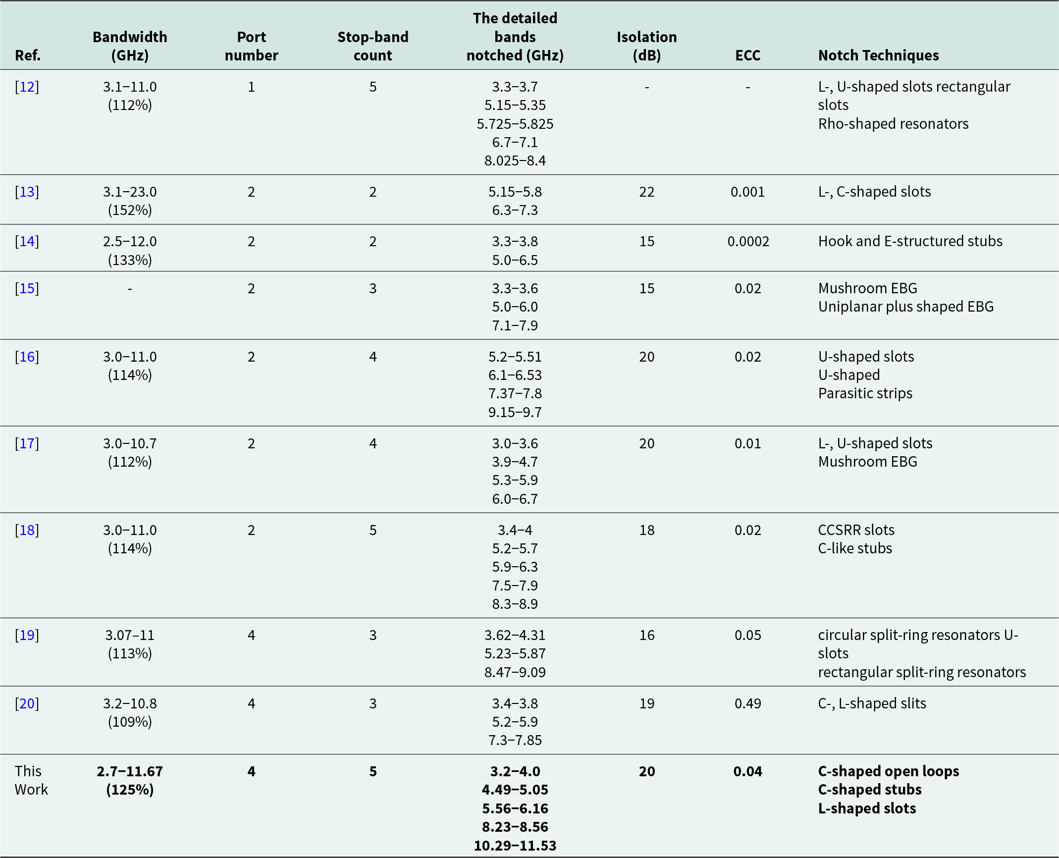
Table 2 offers a review of the operational characteristics of the four-port MIMO antenna with quintuple band-notched characteristics against previous research studies. Although the antenna designed in [Reference Yang, Zhang, Xuping, Yapeng, Yang and Shi12] achieves quintuple band-notched characteristics, it is conceived as a single-element antenna and does not incorporate MIMO features. Although the antennas in [Reference Benghanem, Mansoul and Mouffok13] and [Reference Tathababu Addepalli, Mrudula Kilaru, Kamili, Kumar, Nimmagadda and Kumar14] have a wider relative bandwidth compared to the antenna designed in this work, they are both dual-port MIMO antennas with only two notched bands. Although the antenna in [Reference Jaglan, Gupta, Thakur, Kumar, Kanaujia and Srivastava15] achieves high gain, it has low isolation and only three band-notched characteristics. In [Reference Luo, Wang, Chen, Ershi and Jiang16, Reference Modak and Khan17], these antennas are only two-element MIMO antennas with quadruple band-stop features. As reported in [Reference Ling, Cao, Yin, Yang and Xiaolin18], with quintuple band-notched characteristics, the dual-port MIMO antenna has lower isolation. In [Reference Arashpreet and Kaur19, Reference Jayant and Srivastava20], although both antennas are four-port designs, they can only suppress interference in three frequency bands. In summary, the recommended four-port MIMO antenna is characterized by its quintuple notched-band, high isolation, compact size, and wide bandwidth. The design ensures suitability for ultra-wideband communication applications.
Performance comparison of antennas

Conclusion
A novel four-element ultra-wideband MIMO antenna exhibiting five stop-band properties is presented. The antenna has dimensions of 0.72λ0 × 0.72λ0 × 0.0072λ0 (λ0 is the free-space wavelength at lowest frequency 2.7 GHz). Measurement results indicate that this antenna encompasses frequencies across the range of 2.7–11.67 GHz, with isolation exceeding 20 dB. It successfully suppresses interference from WiMAX, N79, WLAN downlink, ITU-R, and Ku downlink. Both measurement and simulation results validate the correctness of the design, with measured ECC measurements under 0.04 and DG values exceeding 9.995 across the complete frequency range of operation. The TARC remains below −10 dB within the full range of operational frequencies, indicating the effectiveness of the UWB-MIMO system.
Competing interests
The authors report no conflict of interest.

Chengzhu Du was born in Haikou, Hainan Province, China. She received the BS degree from the Xidian University, MS degree from Nanjing University of Posts and Telecommunications, and PhD degree from Shanghai University, in 1995, 2003, and 2012, respectively, all in electromagnetic wave and microwave technology. She is currently an associate professor of Shanghai University of Electric Power. Her research interests include flexible antenna, multiband and wideband antennas, and MIMO technologies.

Zhiyuan Wang was born in Anhui, China, in 2000. He received the BS degree from the Shanghai University of Electric Power in 2022. He is currently pursuing the MS degree in College of Electronics and Information Engineering, Shanghai University of Electric Power. His research interests include ultra-wideband antennas and MIMO antenna.

Ruomeng Li was born in Shanxi, China, in 1999. She received the BS degree and MS degree from the Shanghai University of Electric Power in 2021 and 2024, respectively. Her research interests include multi-stopband antenna and MIMO antenna.