I. INTRODUCTION
There are many applications in which ceramic and metallic foams exhibit superior properties compared to their bulk counterparts, due to their lower density, lower heat conduction, and higher surface to volume ratio, e.g., for catalysis or sensor applications.Reference Twigg and Richardson1 In particular, porous tungsten oxide is used for a variety of energy and photo-therapeutic usages.Reference Huang, Song, Pan, Zhang, Wang and Zou2 Foams are additionally widely used as scaffolds for metal–metal- and ceramic–metal-composites produced by melt-infiltration,Reference Hamidi, Arabi and Rastegari3–Reference Behrens, Weise, Beiss, Ruthardt and Warlimont5 important examples of which include W–Cu and W–Ag composites for arcing contacts in switchgears,Reference Hamidi, Arabi and Rastegari4–Reference Lassner, Schubert, Lassner and Schubert6 W–Cu for resistance welding electrodes,Reference Lassner, Schubert, Lassner and Schubert6 low coefficient of thermal expansion substrates for heat spreader in power electronicsReference Lassner, Schubert, Lassner and Schubert6 and electrodes for electrical discharge machining.Reference Lassner, Schubert, Lassner and Schubert6,Reference Marafona and Wykes7
Common foam synthesis methodsReference Banhart8,Reference Lefebvre, Banhart and Dunand9 including traditional powder metallurgy (PM) approachesReference Hamidi, Arabi and Rastegari3,Reference Selcuk and Wood10,Reference Lassner and Schubert11 lead to equiaxed pores with an isotropic distribution over the whole foam. For tungsten controlling the pore architecture is difficult or not possible and the resulting structures exhibit isotropic materials properties. Especially in heat sink applications and arcing contacts, a high thermal and electrical conductivity from the heat source into the material is desired to protect the arc region from arc erosion.Reference Soldera, Lasagni, Mucklich, Kaiser and Hrastnik12 Therefore, introducing a directional, anisotropic microstructure can minimize the resistance to current flow and simultaneously increase the thermal conductivity while modifying internal thermal expansion mismatch stresses, opening new design possibilities.
A method to create a directional and anisotropic foam microstructure is freeze-casting and consists in general of four process steps: (i) formation of a ceramic slurry, (ii) casting and solidification of the slurry to form a frozen body with powders segregated in the interdendritic space, (iii) sublimation of the frozen vehicle creating large pores at ice dendrite location surrounded by loosely-bound ceramic walls, and (iv) sintering of the ceramic walls. If a metal is desired, an additional step, often carried out prior to the fourth, consisting of chemical reduction of the ceramic to metal, usually via hydrogen, while maintaining the constructed large porosityReference Deville13–Reference Chino and Dunand17 needs to be introduced. Most literature focuses on freeze casting of ceramics, but a few metallic foams have been created by freeze-casting such as copper from cupric oxide,Reference Ramos and Dunand15 nickel from metallic nickel using a carboxymethylcellulose/gelatin mixture,Reference Fukushima and Yoshizawa18 porous stainless steels tapes from ferritic metallic powderReference Driscoll, Weisenstein and Sofie19 and titanium foams from metallic titanium powder.Reference Chino and Dunand14,Reference Li and Dunand16,Reference Chino and Dunand17 In the latter case, the oxygen content has a strong influence on the mechanical propertiesReference Li and Dunand16 since surface oxides of titanium are not readily reduced under H2. Using water as solvent, growth of lamellar ice dendrites can be achieved by applying a temperature gradient since the ice crystals exhibit a strong anisotropy in crystal growth along the c-axis.Reference Deville13 After sublimation of the ice phase by freeze-drying, a strongly anisotropic foam structure is achieved, exhibiting some strength from the added binder during slurry formation. Besides stabilizing the freeze-dried structure, the binder has an additional pore refinement effect due to the increase in slurry viscosity and resulting decreased binder diffusivity.Reference Pekor and Nettleship20,Reference Pekor, Kisa and Nettleship21
Freeze-casting of high-density refractory metals is difficult due to their tendency to settle in the liquid slurry. Furthermore, the use of metallic nanoparticles to counter this effect is inadvisable due to their high tendency to oxidize and difficulty in production. As a result, only two syntheses of very porous, loosely sintered refractory foams by freeze-casting are reported in literature,Reference Oh, Kim and Suk22,Reference Lee and Oh23 to our knowledge. In these publications, slurries of camphene/naphthalene with 5 vol% MoO3 (Ref. Reference Oh, Kim and Suk22) and camphene with 10–15 vol% WO3 (Ref. Reference Lee and Oh23) were solidified, resulting in high porosity metallic structures, after freeze drying, reduction and sintering. In the case of WO3 slurries, sintering of W at 900 °C without any sintering additives was performed, yielding loosely sintered W foam cell walls with low structural integrity; no mechanical data are reported in these publications.
In the present work, we explore the synthesis, structure, and mechanical properties of freeze-cast tungsten foams created by directional freeze-casting of aqueous WO3 powder slurries followed by chemical reduction and sintering to metallic tungsten. The foam architecture can be controlled by changing the WO3 fraction in the slurry and the casting temperature. Nickel in form of NiO was added to the slurry, co-cast and co-reduced with WO3 to act as sintering activatorReference Toth and Lockington24,Reference Corti25 enabling the production of W foams with densely sintered walls at 1400 °C.
II. EXPERIMENTAL METHODS
A. Slurry preparation
Tungsten trioxide nanoparticles (WO3, 99.95% purity, d < 100 nm, SkySpring Nanomaterials Inc., Houston, Texas) was homogeneously suspended in distilled water using 1 wt% (relative to the amount of WO3) branched polyethylene imine (PEI, M w 25,000, Sigma-Aldrich, Milwaukee, Wisconsin) as dispersant. For most samples, 0.51 wt% nickel oxide nanoparticles (NiO, 99.9% purity, d = 20 nm, Inframat Advanced Materials, Manchester, Connecticut) were added to yield 0.5 wt% nickel in the final reduced and sintered tungsten foam. To achieve homogenous suspensions, the slurries were ball-milled (Spex, Metuchen, New Jersey, Certi Prep 8000 Mixer/Miller) using ZrO2 balls and milling jars for 30 min using 5 min intervals to prevent overheating the slurry. No pH-adjustments were necessary due to the low isoelectric point of WO3 and the resulting stabilization efficiency of PEI.Reference Laarz and Bergstrom26 After ball milling, 2.5 wt% polyethylene glycol (PEG, M n = 3,400, Sigma-Aldrich) relative to WO3 was added as binder to increase the integrity of the freeze-dried green body. The WO3 solid fraction of the slurry was varied between 20 and 35 vol% to investigate the impact of solid fraction on foam total porosity and wall thickness. To achieve the higher solid fractions, the WO3 powder was added in several doses during the milling breaks.
B. Freeze-casting and freeze-drying
A cylindrical copper block was partially put into a Styrofoam box filled with liquid nitrogen (LN2). The bottom of the block was in contact with the LN2 while the topmost part of the block reached outside the Styrofoam. Using a resistive heater, the temperature of the block top surface was regulated and monitored by a thermocouple. A series of experiments with casting temperature T cast of the copper in the range of −30 to −15 °C were conducted to investigate the influence of temperature on pore morphology. An open cylinder mold made of Teflon® with inner and outer diameter of 19 and 25 mm and height of 25 mm was sealed at its bottom with a thin polypropylene foil and silicone vacuum grease and insulated on its sides by Styrofoam. The slurries, typically 5–6 mL in volume, were poured directly from the milling jar into the mold placed on top of the cooled Cu rod. After full solidification, taking 45–60 min depending on casting temperature and slurry volume, the frozen ice billet, typically 20 mm in height, was removed from the mold and put into a freeze-dryer (Freeze Dry System, Model 7754000, Labconco, Kansas City, Missouri) to sublimate for at least 20 h at −40 °C and low pressure (<3 Pa).
C. Reduction and sintering
After freeze-drying, the billets were reduced and sintered under flowing hydrogen (Airgas, Rock Falls, Illinois, Ultra high purity 5.0 grade) in a tube furnace using a three-step temperature programmed reduction (TPR) protocol: (i) organic additive burn-out at 450 °C; (ii) reduction of the oxides to pure metal at 750 °C and (iii) sintering of the foam walls at 1400 °C for 2 h. Heating rates were 8.5 °C/min. up to 1000 °C and then 5 °C/min. Cooling was controlled analogously until 600 °C followed by furnace cooling to room temperature.
D. Characterization
Prior and after heat treatments, the samples were weighed and their dimensions recorded to calculate the mass loss as well as linear shrinkage due to reduction. Helium gas pycnometry (Micrometrics, Norcross, Georgia, Accu Pyc 1330 Gas pycnometer) in conjunction with Archimedes' measurements [according to ASTM standard C20 (Ref. 27)] were performed to quantify the open and closed porosity as well as foam wall density.
For optical analysis, radial and longitudinal cross-sections (perpendicular and parallel to ice-front growth direction, respectively) were cut and prepared according to standard metallography preparation. The metallographic cross-sections were analyzed using light microscopy for their morphology, and their wall thickness was determined from radial metallographic cross-sections using a custom-designed Matlab® routine by intersecting the parallel foam wall boundaries with perpendicular lines and quantifying the distance between intersection points. This procedure was applied at least five times per wall and five walls per sample were investigated to achieve reliable statistics.
Secondary electron (SE) and back scattered electron (BSE) images were taken from cleaved surfaces using two different microscopes (Tescan, Dortmund, Germany, Eo-Scan Vega XL and FEI, Quanta 200F, Hillsboro, Oregon), the latter being used for energy dispersive X-ray (EDX) mappings as well. X-ray diffraction (XRD) was performed to identify the crystallographic phase of the as-received powder and the final foam to verify full reduction on an Empyrean diffractometer (PANalytical, Almelo, The Netherlands).
Hardness and reduced Young's modulus quantification of individual cell walls was performed by means of nanoindentation (CSM ultra nanoindentation tester, Anton Paar, Graz, Austria) using a Berkovich diamond tip and the Oliver–Pharr methodReference Oliver and Pharr28 for data processing. For the compressive stiffness and strength measurements, four foams were machined by a lathe to cylindrical compression test specimen with height of 12–13 mm and aspect ratio 2:1; compression tests were carried out at a strain rate of ∼10−4 s−1 on two foams at room temperature and at 400 °C in air, respectively. The latter temperature was chosen to be well above the brittle-to-ductile transition temperature (BDTT) of tungsten reported to lie between 280–330 °C (Ref. Reference Lassner, Schubert, Lassner and Schubert29) depending mainly on impurity concentrationReference Giannattasio, Yao, Tarleton and Roberts30 and strain rate.Reference Giannattasio and Roberts31 The compression tests were performed using a screw-driven mechanical testing machine employing constant crosshead displacement rate set to yield a strain rate of ∼10−4 s−1 confirmed by the strain measurement conducted by means of digital image correlation. For the compression tests at elevated temperature, an environmental chamber with convective heating was used. In all cases the loading axis was chosen parallel to the ice-front growth direction.
III. RESULTS
A. Synthesis
A total of 29 foams were synthesized using the freeze-casting method described above and the most important process and foam parameters are summarized in Table I. The four additional samples used for mechanical testing are listed in Table II. A large linear shrinkage (47–51%) is displayed for all samples sintered above 1250 °C with Ni as sintering agent [a representative example, foam 18, is shown in Fig. 1(a)] but the shrinkage is less pronounced (32–35%) for foams synthesized without Ni. Open porosity decreases with increasing sintering temperature (as seen when comparing foams 7–9) as well as with increasing tungsten oxide volume fraction. Renouncing nickel as a sintering additive leads to lower cell wall density and therefore to higher porosity values (open and closed).
Overview of synthesized W-foams parameters listing WO3 volume fraction in the initial slurry f WO3, casting temperature T cast, sintering temperature T sinter and linear shrinkage Δl/l. Open porosity values were calculated from He-pycnometry and Archimedes' measurements and the tungsten cell wall density ρcell was determined by He-pycnometry. The closed porosity was deduced from ρcell and the wall thickness optically measured. Samples marked with * were synthesized without the use of Ni as a sintering agent.

Table of W-foams parameters used for compression tests with furnace temperature T test, linear shrinkage Δl/l, compressive stiffness of the foam S comp with standard deviation and compressive strength σcomp. Open porosity values were calculated from He-pycnometry and Archimedes' measurements and the tungsten cell wall density ρcell was determined by He-pycnometry. The closed porosity was deduced from ρcell.
(a) Macrographs of WO3 foam after freeze-drying (left) and after reduction and sintering under flowing H2 (right) using a solid fraction of 27.5 vol% WO3 and a casting temperature of −20 °C (foam 18), illustrating the color change from greenish-yellow to shiny gray and the large, isotropic volume shrinkage. (b) XRD-spectra of initial, dry monoclinic WO3 nanopowder (bottom) and reduced bcc W-foam phase (top). The main bcc-reflections (space group  $Im\bar 3m$) are indicated by dashed lines according to Ref. 52. For visibility reasons the m-WO3 reflections are not indexed but the phase is confirmed to be monoclinic WO3 (space group P21/n) according to Ref. 53.
To confirm total reduction of the freeze-dried WO3 foams into metallic tungsten foams, XRD spectra were taken and compared to the as-received WO3 nanopowder. A representative comparison is given in Fig. 1(b) highlighting the complete absence of any WO3-peaks in the foam structure confirming full reduction during TPR. For better visibility, the WO3 reflections are not marked due to the complexity and multitude of reflection in the monoclinic WO3 phase. As expected, the final foam phase is body centered cubic tungsten which is the stable room temperature phase.
The foam structure is highly anisotropic (Fig. 2) with walls aligned along the temperature gradient (along the cylinder axis of the mold). The radial cross-sections show regions or colonies consisting of a few to dozens of parallel walls, which are randomly orientated in the plane perpendicular to the ice-growth direction.
(a) Radial and (b) longitudinal metallographic cross-sections of representative W foams, taken at the same magnification to ease comparison, as function of the main process parameter oxide volume fraction in the slurry  ${f_{{\rm{W}}{{\rm{O}}_3}}}$ and freeze casting temperature T cast. Only foams with nickel as sintering additive are shown. Tungsten foam walls appear bright white in contrast to porosity in black. Coloring is used to guide the reader's eye.
B. Open porosity, linear shrinkage, and wall thickness
Three important parameters for foams are the open porosity, the linear shrinkage, and the thickness of individual cell walls, since they stand for the density reduction compared to their bulk counterparts (open porosity), densification ability (linear shrinkage), and finesse of the resulting microstructure (wall thickness). Open porosity and linear shrinkage are plotted in Figs. 3(a) and 3(b) against the volume fraction of WO3 in the initial slurry while the wall thickness is plotted against freezing temperature in Fig. 3(c). Increasing the oxide volume fraction in the slurry leads to a decrease in open porosity and an increase in their wall thickness, i.e., a coarser microstructure. Conversely a reduction in freeze-casting temperature leads to a finer microstructure (as also visible in Fig. 2).
Plots showing the dependence of WO3 fraction in the slurry of (a) foam open porosity and (b) foam linear shrinkage after reduction and sintering. (c) Plot of foam wall thickness versus freeze-casting temperature for different slurry solid fraction with same coloring scheme as used in Fig. 2. Only samples with nickel as sintering agent were used for all graphs. Best linear fits are plotted as guide to the eye.
C. Effect of nickel and sintering temperature on densification
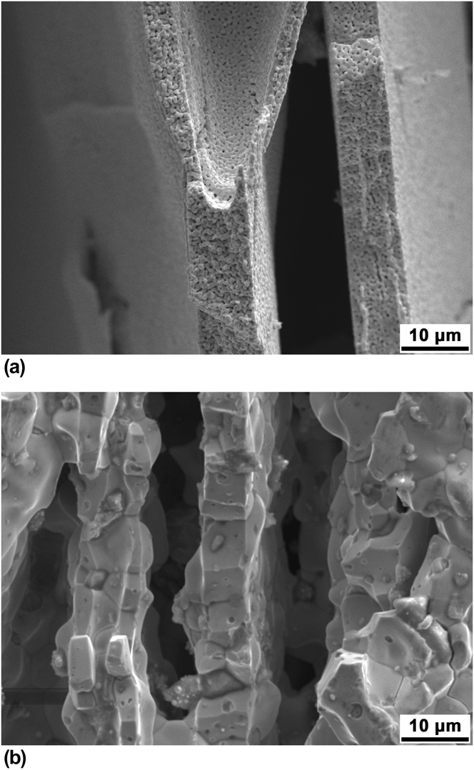
Most foams were synthesized using nickel as sintering agent to enhance the sintering of tungsten, as Ni is commonly used in traditional PM as a sintering additive.Reference Corti25,Reference Lassner, Schubert, Lassner and Schubert32 The effect of nickel on the foam microstructure is illustrated in Fig. 4. Sintering at 1400 °C without the use of nickel leads to lower densification of tungsten walls, thus increasing the surface to volume ratio of the foam, i.e., the microporosity (Fig. 4(a), foam 26), and as shown in Table I, leads in general to a higher open porosity and lower linear shrinkage. The W grain size remains therefore small (<1 µm) and the structural integrity of the foams is poor due to limited densification of the walls. By adding Ni, near-full densification of tungsten walls is achieved, with the exception of a few closed pores [Fig. 4(b), foam 1]. Significant grain growth is observed (∼10 µm) and the foam walls exhibit a bamboo-like grain structure.
SE micrographs of cleaved samples sintered at 1400 °C freeze-cast without (a, foam 26) and with (b, foam 1) the use of nickel as sintering agent.
Foam densification is higher when using nickel, as seen in the linear shrinkage and open porosity values when comparing foams with similar WO3 volume fraction in the slurry (Table I). For example, comparing foam 6 with foam 28 (both have 22.5 vol% WO3, T cast = −15 °C and T sinter = 1400 °C) leads to the following three observations when using nickel in the freeze-casting process: (i) the linear shrinkage shows a 1.4 fold increase, from 34.1 to 47.6%; (ii) the open porosity decreases by ∼10% from 66.6 to 57.6%; (iii) the cell wall density increases, and therefore the closed porosity value decreases, by a factor ∼3, from 10.0 to 3.6%.
Reducing the sintering temperature from 1400 to 1250 and 1100 °C has little impact on linear shrinkage and closed porosity (foam 7–9) but the open porosity is significantly increased, indicating a reduction in wall sintering. The microporosity follows the same trend as the open porosity (Fig. 5), being higher at lower temperature. Unlike for foams sintered at 1400 °C, the bamboo-grain structure is not discernible from the BSE micrograph at the lowest sintering temperature of 1100 °C. Grain growth is promoted by increasing the sintering temperature to 1250 °C and the early stages of the formation of the characteristic bamboo microstructure are visible for sintering temperatures of 1250 °C, as indicated by arrows in Fig. 5(b). Additionally the EDX-mapping overlay of the Ni–L and W–M line [Fig. 5(d)] highlights an enrichment of nickel at grain boundaries. These lines were chosen because of an overlap of the W–L and Ni–K lines.
BSE micrographs of cleaved samples sintered at (a) 1100 °C (foam 9), (b) 1250 °C (foam 8), and (c) 1400 °C (foam 7). At 1250 °C the initiation of the bamboo-structure is discernible and indicated with arrows. (d) Overlay EDX-mapping taken from Ni–L (green) and W–M lines (blue) corresponding to the area shown in (c) are shown, highlighting nickel enrichment at grain boundaries as well as closed pores.
D. Mechanical properties
The four foams used for compressive mechanical testing were all freeze-cast using identical process parameters as foam 18 (27.5 vol% WO3, T cast = −20 °C, and T sinter = 1400 °C). The foam properties are listed in Table II and their stress–strain curves are given in Fig. 6. The curves show characteristic behavior for brittle foams, with low yield stresses (20–40 MPa) and peak stresses of 70–96 MPa (25 °C) and 92–130 MPa (400 °C), followed by sharp stress-drops and a plateau stress showing multiple serrations. The plateau stress is significantly higher, a factor of 3–4, at 400 °C than at 25 °C. The samples deformed at room temperature fractured gradually into small flakes during deformation at the plateau stress. The foams tested at 400 °C, by contrast, showed a brooming behavior indicative of a more ductile behavior, resulting in densification when approaching the maximum compressive strain. Furthermore, hardness values of 10.4 ± 1.7 GPa (±standard deviation is used henceforth), Young's modulus of 371 ± 53 GPa and reduced Young's modulus of 279 ± 30 GPa were measured by nanoindentation indicate that closed porosity influences the measurements as discussed below.
Stress–strain curves of foams listed in Table II with open porosity (44–48%) and test temperature (25 and 400 ºC) in parentheses. The compressive stiffness is comparable for all measured foams but compressive strength and plateau stress is higher for the foams tested at high temperatures.
IV. DISCUSSION
A. Foam morphology
All samples show a typical freeze-cast microstructure with colonies of parallel metallic walls, aligned along the applied temperature gradient and with their normals randomly orientated perpendicular to the ice-growth direction (Fig. 2). This is comparable to the typical structures presented in the literature for freeze-casting of aqueous suspensions.Reference Chino and Dunand14–Reference Chino and Dunand17,Reference Dunand33 The structure can be explained by the growth kinetics of the ice crystals which is replicated as pores or channels, as explained in detail in the literature.Reference Deville13
Decreasing the casting temperature as well as decreasing the particle volume fraction leads to smaller wall thickness in the final foam [Fig. 3(c)]. In general, a power–law relationship between ice growth front velocity and lamellae thickness is inferred.Reference Dunand33 This would lead to the conclusion that increasing the volume fraction of WO3 in the slurry increases the solidification front velocity, i.e., favoring heat transfer. In reality such a correlation is difficult to prove. The heat capacity C p of water and WO3 both at 0 °C differ only slightly, 76 and 72 J/(mol K)Reference Lemmon, Harvey and Haynes34,Reference King, Christensen and Weller35 with ice being 38 J/(mol K).Reference Harvey and Haynes36 In contrast, the thermal conductivity of WO3 is estimated to lie higher than that of water or ice at 0 °C, being 0.6 and 2.2 W/(m K).Reference Lemmon, Harvey and Haynes34,Reference Harvey and Haynes36 Both arguments would favor increased heat transfer, but the thermal diffusivity which is important in this time-dependent process, includes the densities of the species as well which increase strongly with the addition of WO3 (7.2 g/cm3)Reference Haynes37 compared to that of water or ice (∼1 g/cm3).Reference Lemmon, Harvey and Haynes34,Reference Harvey and Haynes36 Therefore whether this change in heat transfer properties at the water–ice-particle interface indeed leads to an acceleration of the solidification front remains unclear. Another reason for the increased wall thickness with solid fraction could be explained as follows: the initially homogenously distributed WO3 nanoparticles are rejected by the growing ice front and a nonplanar solidification front morphology concentrates the rejected particles in the interdendritic space. This nonplanar solidification front is addressed by Deville et al.Reference Deville13,Reference Deville, Saiz, Nalla and Tomsia38 During rejection of the WO3 particle at the ice/water interface of each dendrite, the volume fraction of particle in the remaining liquid is increased until a so-called “breakthrough fraction” is reached. At this point, the ice front penetrates the interparticle space and the particles are no longer pushed into the interdendritic space.Reference Shanti, Araki and Halloran39 At this stage, the wall thickness is determined by the amount of particles entrapped between the growing ice lamellae. Having a higher volume fraction of WO3 in the initial homogenous slurry leads to smaller interparticle distances; thus, for identical ice nucleation and growth kinetics (i.e., the same casting temperature) more particles are rejected into the interdendritic space during ice solidification and thicker walls are achieved when the breakthrough fraction is reached. Analogous findings on the effect of solid fraction on wall thickness in aqueous directional freeze-casting were published for porous Al2O3–ZrO2.Reference Liu, Zhang, Meggs and Button40
Conversely, for the same interparticle distance in the slurry (i.e., same solid volume fraction in the slurry) but lower casting temperature, a finer foam architecture is achieved since the nucleation and growth conditions for the ice crystals have changed. A lower casting temperature increases the ice nucleation rate, the ice-front growth velocity and the temperature gradient, altering the morphology of the solidification front. When the solidification front speed increases due to higher supercooling, i.e., lower casting temperatures, the width of the interdendritic channels is reduced.Reference Deville13 This leads to a smaller wall thickness because fewer particles are collected between the ice lamellae. As the extent of densification during sintering is constant, the wall thickness is determined by particle redistribution during slurry solidification.
To summarize, the particle concentration is constant within the cross-section, since little or no sedimentation of WO3 during freezing occurs. Therefore increasing the volume fraction increases the wall thickness.
The open porosity follows a linear trend with solid fraction: a reduction of 1% in WO3 slurry fraction leads to a reduction of ∼2% in the foam open porosity, Fig. 3(a); this allows to control the foam open porosity by adjusting the slurry solid fractions irrespective of casting temperature. Solid fractions as low as 15 vol% and as high as 35 vol% were cast but these do not represent lower and upper limits. Extrapolating the linear fit in Fig. 3(a) to the x-axis intersection suggest an upper limit of 48 vol% WO3. The limit is unlikely to be reached, since the critical ice front velocity for engulfing of the particles during solidification is inversely proportional to the viscosity of the slurry.Reference Zhang, Hussain, Brust, Butler, Rannard and Cooper41 As the solid fraction of the slurry increases, so does its viscosity until it becomes not pourable. Nevertheless, the broad range of 29–66% in foam open porosity achieved in this study lies in the suitable region for melt-infiltrated composites.
The amount of PEG added was always adapted to yield 2.5 wt% with respect to the amount of WO3 used. This leads to significant PEG concentration changes within the aqueous slurry with respect to the amount of water, since for higher solid fractions more PEG was needed while simultaneously decreasing the water fraction. The concentration of PEG in the slurry with respect to the water content changed between ∼3 and 9 wt% for 15–35 vol% solid fraction, respectively. As reported in the literatureReference Pekor and Nettleship20,Reference Pekor, Kisa and Nettleship21 there is no significant influence of PEG concentration on foam microstructure.
B. Effect of nickel on sintering behavior and foam microstructure
Adding NiO to the WO3 particle slurry, freeze-casting and co-reducing the mixture of oxide and co-sintering the resulting Ni-doped W has a large impact on the foam microstructure, by increasing the tungsten wall densification, reducing the open and closed porosity and increasing grain size. Sintering without nickel leads to a linear shrinkage in the range of 30–40% which is mainly accounted for by the volume shrinkage due to the conversion of WO3 to W, given the low levels of sintering. The theoretical linear shrinkage due to oxide reduction is 33.4%, as calculated by considering conservation of volume (without sintering) and density values of W and WO3. During sintering, the reduced tungsten particles densify into pore-free W walls giving rise to an additional linear shrinkage of 9–20% depending on packing density of the W particles within the walls after reduction and final closed porosity. The addition of nickel intensifies the densification during sintering as explained in the following. The sintering length change is expected to achieve 42–53% after full sintering of the W powders, depending on packing density of the walls after reduction, and agrees with the experimental values for all foams. Nickel-free foams hardly sinter and therefore their linear shrinkage lies in the range of full reduction only.
Nickel has a low maximum solubility in tungsten (<1.1 at.%) in the present sintering temperature range,Reference Predel and Madelung42 which is below the Ni concentration used here (1.55 at.% or 0.5 wt% Ni). Tungsten on the hand is soluble in nickel up to 16.5 at.% at 1400 °C (16.0 at.% at 1100 °C). As a result, during sintering, nickel is not diffusing significantly into tungsten but rather coats the tungsten nanoparticles with a very thin disordered Ni-layer.Reference Toth and Lockington24,Reference Corti25,Reference Brophy, Hayden and Wulff43 This effect is also exploited in traditional PM manufacturing processes where nickel-doped tungsten powder is created by dissolving nickel chloride in methanol, mixing with tungsten powder and reducing at 600–800 °C to enhance the sintering activity.Reference Hamidi, Arabi and Rastegari3,Reference Gupta, Yoon, Meyer and Luo44 This is in agreement with the results of Hamidi et al.Reference Hamidi, Arabi and Rastegari3 who observed a W-surface transformation above 1100 °C due to nickel segregation at grain boundaries and at free surfaces. An intergranular, nickel-enriched film which is held responsible for activated sintering is formed, which does not lead to significant densification in itself but fills the interparticle space.Reference Toth and Lockington24,Reference Corti25,Reference Gupta, Yoon, Meyer and Luo44 The presence of a nickel-enriched phase at grain boundaries is highlighted with the EDX-maps in Fig. 5(d), where nickel-rich inclusions are observed at grain boundary junctions. Furthermore, since tungsten fractures almost exclusively intergranularly at 25 °C, the surfaces visible in all BSE images in Fig. 5 correspond to grain boundaries. The volume fraction of nickel in the specimen corresponds to 1.1 vol%. The area fraction of Ni-enriched phases within the BSE images, but especially for Fig. 5(c), corresponds to a much higher value, estimated at 25% of the area, corroborating a large Ni-enrichment at grain boundaries.
The reason for higher densification already at 1100 °C with Ni (foam 9), as compared to foams sintered at 1400 °C without using nickel (foams 26–29), is found in the very different diffusion parameters for tungsten in nickel compared to tungsten self-diffusion, combined with the bridged interparticle space, reducing the closed porosity and increasing apparent wall density already at sintering temperatures as low as 1100 °C.
Tungsten self-diffusion at 1400 °C has an activation energy as high as 500–600 kJ/mol and resulting diffusion coefficient of ∼10−22 m2/s, depending on the source.Reference Mehrer, Stolica, Stolwijk and Mehrer45,Reference LeClaire, Neumann and Mehrer46 The impurity diffusion of tungsten in nickel however has a much lower activation energy of 323 kJ/mol, yielding a diffusion coefficient of ∼10−13 m2/s (Refs. Reference LeClaire, Neumann and Mehrer46 and Reference Murch, Bruff and Mehrer47) at 1400 °C. However, the significantly enhanced volume diffusion of tungsten in nickel is not solely responsible for the higher densification during sintering; as explained by Toth and Lockington,Reference Toth and Lockington24 the process includes dissolution of tungsten in the disordered nickel layer, volume diffusion of tungsten outwards through the nickel, surface diffusion of tungsten on nickel, uphill diffusion of tungsten to deposit at the particle interface due to energy reduction by reducing the surface area and resulting formation of sintering necks.
Gupta et al.Reference Gupta, Yoon, Meyer and Luo44 confirmed the existence of a disordered, quasiliquid nanometer thick nickel film at grain boundaries after tungsten sintering by high-resolution transmission electron microscopy. Such quasiliquid films are expected to exhibit high free volume and therefore can provide a short-circuit diffusion path for tungsten lowering the activation energy and increasing the kinetics for tungsten sintering. To form such quasiliquid phases, a minimum nickel content of 0.3–0.4 wt% was inferred.Reference Gupta, Yoon, Meyer and Luo44
The effect on densification is primarily visible in the open porosity and in the linear shrinkage and is observed by comparing the SE-micrographs of foams sintered without nickel addition which show microstructure with discernible individual tungsten particles [Fig. 4(a)] to the SE-micrographs taken for the foams sintered at 1400 °C [Fig. 4(b)]. By sintering at 1100 °C the particle-like shape is retained but the interparticle space is clearly bridged by already formed sintering necks [Fig. 5(a)].
C. Mechanical properties
The stress–strain curves of the foams (Fig. 6) are indicative of a brittle foam material: (i) Peak stress followed by a lower plateau stress and (ii) ragged plateau stress range, with many serrations. However, the compressive behavior at 400 °C is more ductile than at 25 °C, as expected given that the W walls are deforming above and below the W BDTT respectively. In particular, higher plateau stresses by factor of 3–4 and increased compressive strengths from 70–96 to 92–130 MPa are observed for the samples deformed at 400 °C (Fig. 6), highlighting the transition from brittle deformation at ambient temperature to partial ductility at 400 °C. Yield point estimation is very difficult since no sharp yield point is observed but is estimated to be around 20–30 MPa for both temperatures. All samples were tested with the load axis parallel to the directional porosity and although the sample aspect ratio is chosen to prevent buckling, the very high aspect ratio of individual tungsten walls implies that elastic and plastic buckling of walls, individually or cooperatively within colonies, is a likely deformation mechanism. Wall buckling is however mitigated by wall-to-wall bridges created during solidificationReference Deville13,Reference Deville, Saiz, Nalla and Tomsia38 (Fig. 4) and by the interaction of neighboring colonies of varying orientations in the radial plane.Reference Lichtner, Roussel, Jauffrès, Martin and Bordia48 Additionally, wall fracture is a likely deformation mechanism, especially at ambient temperature below the BDTT of tungsten.
Nanoindentation results are in reasonable agreement with expectations. The hardness value of 10.4 ± 1.7 GPa is higher by a factor of 2–3 than results reported in literature for bulk tungsten measured by micro-indentation.Reference Lassner, Schubert, Lassner and Schubert29 The Young's modulus derived using the Oliver and Pharr methodReference Oliver and Pharr28 (E = 371 ± 53 GPa) is consistent, within the large experimental error, with literature values for bulk tungsten [E W = 405 GPa (Ref. Reference Lassner, Schubert, Lassner and Schubert29)]. This difference lies within the measurement error and is attributed to the sensitivity of the measurement setup. Deformation of the compliant polymer matrix needed for sample preparation analogously to metallography preparation and the likely presence of unobserved submicron pores in the indent vicinity result in a reduction and scatter of the measured data. Hardness values on the other hand are much less influenced by those factors since the plastic zone of an indent remains very confined compared to the elastic zone influencing the modulus calculation. Given these considerations, a good agreement is obtained between measured and bulk values, strengthening the claim that near-dense and fully-reduced tungsten walls are achieved.
D. Engineering applications
In applications where a reasonable mechanical strength is required, higher solid fractions and higher casting temperatures, thus increasing the wall thickness and decreasing the total porosity, is advisable, together with the use of nickel as a sintering aid and sintering temperatures of at least 1400 °C. Such applications include tungsten scaffolds for biomedical implantReference Peuster, Kaese, Wuensch, von Schnakenburg, Niemeyer, Fink, Haferkamp and Hausdorf49 or light-weight, lead-free radiation shielding,Reference Yue, Luo, Dong, Wang, Wu, Jiang and Zha50 as well as foams which are subsequently melt-infiltrated with copper to create W–Cu composites for electrical contact materials.Reference Hamidi, Arabi and Rastegari4–Reference Lassner, Schubert, Lassner and Schubert6 In all the above cases, directional pores are beneficial due to the enhanced strength in the direction of the aligned walls. Such composites may also be used for heat spreaders in power electronicsReference Lassner, Schubert, Lassner and Schubert6 due to their unusual combination of low thermal expansion and high thermal conductivity, which is expected to be anisotropic due to highly aligned W wall microstructure providing another level of customization.
In the case of catalysis and sensor applications where tungstenReference Lassner, Schubert, Lassner and Schubert51 or tungsten oxideReference Huang, Song, Pan, Zhang, Wang and Zou2 with a high open porosity and large surface area is desired, low sintering and low casting temperatures as well as moderate to low solid fraction to increase the open porosity is suggested; for these applications, the high permeability and low pressure drop of these foams with highly aligned macroporosity is advantageous. Renouncing nickel as sintering agent might be considered for such non-load-bearing applications to further increase the surface area but is associated with low mechanical integrity of the foams, for the processing parameters studied here.
V. CONCLUSIONS
Tungsten foams with aligned wall architecture and adjustable porosity were created by directionally freeze-cast aqueous WO3 slurries followed by hydrogen reduction of the oxide and sintering of the W walls. The addition of NiO to the WO3 slurry allows Ni-activated sintering of tungsten walls to near full density. Slurry volume fractions of 15–35 vol% were successfully cast and upon reduction and sintering, the total foam porosity ranges from 27 to 66% (29–75% for total porosity); when Ni is not used as sintering aid, a total porosity as high as 76% (of which 13% is closed within walls) can be achieved. Open porosity, in the form of channels between aligned, elongated W walls, is proportional to the WO3 slurry solid fraction. Casting temperature also affects pore architecture and foam morphology. Lowering the casting temperature increases solidification front velocity reducing the wall thickness. Fine cell walls with 10–50 µm thickness and bamboo grains are created. The microporosity and surface to volume ratio can be increased by sintering at lower temperatures or by not using nickel as sintering agent.
Uniaxial compressive testing of foams and nanoindentation of individual W walls were conducted, demonstrating the brittle nature of the foams at room temperature which however show reasonable plasticity at 400 °C, which is above the BDTT of tungsten (280–330 °C). Individual tungsten walls show good performance in nanoindentation experiments confirming that they are fully sintered, with low closed porosity and no residual oxide, as confirmed by XRD analysis.
ACKNOWLEDGMENTS
The authors thank the Scientific Center for Optical and Electron Microscopy (ScopeM) at the ETH Zürich and the Optical Microscopy and Metallography Facility at Northwestern University (NU) for their support, as well as Ms. A.A. Plunk (NU) for helping with sample synthesis and Mr. A. Reiser for EDX-mappings. The project was funded by the Competence Center for Materials Science and Technology (CCMX), Switzerland, and Plansee Powertech AG, represented by Dr. F.E.H. Müller and Mr. M. Böning whose helpful inputs and knowledge of refractory metals are appreciated.