Introduction
The microstrip antennas (MSAs) are the most preferred form of radiators in several applications. Improvement of the front-to-back ratio of the MSA [Reference Kim and Lee1] is one of the important aspects of the design since it minimizes the wastage of the radiated power as well as the electromagnetic interference (EMI). Moreover, in mobile communications, the mitigation of the multipath signals also requires the use of low back lobe antenna [Reference Lim, Jang and Yu2]. The reasons for the appearance of the back lobe are surface wave excitation along with strong dependence on the surface surrounding the antenna. Some of the techniques used in the past to reduce the back lobe of planar soft surfaces [Reference Umair, Uddin, Ullah, Latef, Mahadi and Othman3] choke ring ground plane [Reference Tranquilla, Carr and Al-Rizzo4], vertical choke ring [Reference Lee and Ganguly5], Electromagnetic Bandgap (EBG) structure [Reference Baggen, Vázquez, Leiss, Holzwarth, Drioli and Maagt6], artificial magnetic conductors [Reference Hurtado, Klimczak, Dutton and McKinzie7] etc. Most of these techniques increase the antenna size significantly. The use of the absorbing layer is an alternate efficient solution to address these problems. The planar periodic conducting patterns on dielectric substrate namely the frequency selective surface (FSS) with ground plane on the bottom is the most common form of electromagnetic (EM) absorbers [Reference Anwar, Mao and Ning8] with sharp resonances and high absorption peaks. The FSS consists of two-dimensional (2D) arrays of printed lossy or lossless elements arranged periodically on the dielectric substrate. The design of lossy FSS [Reference Costa, Monorchio and Manara9] is based on minimizing the scattered field by introducing the ohmic or/and dielectric loss in the FSS element while the lossless FSS [Reference Munk, Munk and Pryor10] employs low loss metallic patterns. A hybrid technique employing both lossy and lossless approach [Reference Simms and Fusco11] is also used to enhance the characteristics of the absorbers significantly. The shape, size, and periodicity of the FSS element are the parameters responsible for the resonance condition. If all the parameters of the FSS are set properly, the incoming incident EM field can be absorbed completely. In the past, the FSS is mostly integrated with the patch antenna for enhancing the directivity and gain [Reference Yeo and Mittra12–Reference Thakur, Yadava and Das16], where it is used as a superstrate layer by placing on the top of the patch antenna. In the proposed work, it is placed below the substrate of the patch antenna to suppress the radiation for EMI mitigation.
This paper aims to examine the radiation characteristics of the MSA placed over the FSS absorber and at the same time to establish its potential use in high frequency/high-speed circuits for mitigating EMI in terms of radiation and crosstalk from the traces of the printed circuit board. The design and configuration of the proposed FSS absorber are presented in the section ‘Design and configuration of FSS-based absorber’. In the sections ‘Design and configuration of an FSS absorber integrated MSA’ and ‘Results and discussion’, the design, simulation, and experimental results of the MSA integrated with the absorber are described and finally, the conclusions are presented in the last section.
Design and configuration of FSS-based absorber
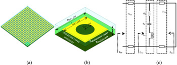
The FSS can be used to transmit, reflect, or absorb the plane wave completely or partially, depending on the nature of the array element. The design of FSS-based EM absorbers mainly depends on two sets of design parameters. The first one being the substrate parameter involving the substrate dielectric constant, loss tangent, and its thickness. The second set of parameters is concerned with conducting patch design, its shape, its geometrical parameters, conducting material parameters, and its layout for the other patches. The proposed FSS absorber consists of a periodic pattern of a slot array as shown in Fig. 1(a) printed over a low-cost FR4 dielectric substrate of dielectric constant 4.4, thickness 1.6 mm, loss tangent tanδ = 0.02, and covered with a dielectric sheet of the same thickness having the same material parameter. The bottom part is the conducting ground plane. The FSS is designed with a dielectric cover so that the cover may be used for printing the antenna element for the integration of this FSS absorber with the antenna. The unit cell of the FSS element consists of a simple circular slot etched rectangular patch with the dielectric cover as shown in Fig. 1(b). The equivalent circuit of the proposed structure is shown in Fig. 3(c). As seen in Fig. 1(c) ZSU is the impedance of the superstrate layer represented in the form of the transmission line TLSU, ZFSS is the impedance of the FSS resonant structure and ZSL is the impedance of the lower substrate layer with a common ground plane represented in the form of a short-circuited transmission line. The geometrical parameters of the unit cell and its periodicity are selected such that the absorber exhibits the absorption characteristics at the desired frequency of operation.
(a) FSS-based absorber configuration. (b) Unit cell of FSS-based absorber. (c) Equivalent circuit of FSS-based absorber.

The design parameters of the absorber are presented in Table 1. The circuit parameters obtained from the equivalent circuit approach are shown in Table 2. It should be noted that the conventional absorbers are designed to absorb the incoming plane wave falling on the absorbing surface such that the impedance of the absorbing layer is properly matched with the free space impedance. However, in the proposed absorber, since the absorber is sandwiched between the patch and ground plane, the impedance of the absorber is to be matched with 50 Ω instead of free space impedance. This in turn requires the selection of appropriate FSS element and cell dimension. The control of these parameters for 50 Ω impedance matching, while maintaining a compact unit cell is a challenging task. However, an array configuration consisting of a complementary slot pattern accomplishes this requirement. The geometrical parameters of the FSS are, therefore tuned for 50 Ω impedance matching condition. The equivalent circuit of the absorber is shown in Fig. 1(c), where, the superstrate layer depicting an impedance of ZSU lying over the FSS pattern is equivalent to a transmission line represented as TLSU, the FSS layer is represented as a series RLC symbolizing an impedance of Z fss whereas the lowest layer of impedance ZSC containing the ground plane is represented as a short-circuited transmission line. The RLC circuit can be expressed as a combination of resistance and reactance [Reference Song, Ding and Guo17] which can be obtained analytically using equations (1) and (2)


where ω 1 and ω 2 are the two angular resonating frequencies. The equivalent circuit model is simulated usingadvanced design system (ADS) software and the design parameters are obtained at an operating frequency of 5.16 GHz. The equivalent circuit model not only offers an insight into the design of the absorber but also helps in tuning the geometrical parameters to obtain the desired results. The absorption characteristics of the proposed absorber can be determined using the reflection characteristics as

Dimensions of FSS-based absorber (all dimensions are in mm)

Equivalent circuit parameters of FSS-based absorbers as shown in Fig. 1(c)

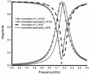
The absorber, thus designed is simulated using Ansys HFSS EM simulation software which uses highly accurate finite element method for analysis. The simulation is performed for the same operating frequency of 5.16 GHz and the results are compared with the results obtained using the ADS simulation tool as shown in Fig. 2. Fairly good agreement is depicted in the figure. Next, the proposed absorber is integrated with the MSA and the radiation characteristics of the composite structure are examined.
Comparison of absorption characteristic of the proposed absorber.

Design and configuration of an FSS absorber integrated MSA
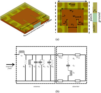
The FSS absorber thus designed is integrated with the MSA by placing the antenna configuration on the top of the superstrate layer of the absorber. A conventional inset fed MSA consisting of a rectangular patch is placed over the superstrate layer of the absorber symmetrically. The isometric, top, and side views of the proposed structure are shown in Fig. 3(a) and the equivalent circuit of the proposed structure is shown in Fig. 3(b). The equivalent circuit of the proposed structure constitutes two sections, one representing the MSA printed on the top layer of the dielectric and the other one representing the absorber. The dimensions of the patch are selected such that it resonates at the frequency of designed absorber, i.e. 5.16 GHz. However, integrating the antenna with the absorber shifts the resonant frequency to 4.42 GHz indicating that effective absorption is obtained at 4.42 GHz, instead of 5.16 GHz. Therefore, all the characteristics of the proposed structure are examined at 4.42 GHz.
(a) Isometric, top and side views of the proposed structure. (b) Equivalent circuit of the proposed structure.

The dimensions of the proposed structure as obtained are shown in Table 3. The equivalent circuit of the proposed structure is simulated in ADS simulation software and the design parameters are listed in Table 4.
Structural dimensions of the proposed structure (all dimensions are in mm)

Equivalent circuit parameters of the proposed structure as shown in Fig. 3(b)

Results and discussion
The reflection coefficient obtained by the equivalent circuit model and simulated in ADS tool is compared with the simulation result using HFSS solver to confirm the validity of the equivalent circuit model for the proposed structure. The comparison results are shown in Fig. 4(a). As seen, the two results match very well thus confirming the validity of the equivalent circuit model. A comparison of the bandwidth of the conventional MSA and proposed structure is shown in Fig. 4(b). The proposed structure shows a reduction in 3 dB bandwidth by more than 50%.
Comparison of reflection coefficient: (a) for the proposed structure using HFSS and ADS simulation tool; (b) for the conventional MSA and proposed structure.

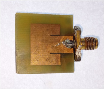
Next, a prototype model of the proposed structure as shown in Fig. 5. is fabricated and measured. A PNA series vector network analyzer is used for the measurement of the S-parameters.
The fabricated prototype model of the proposed structure.

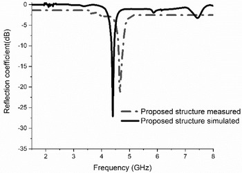
The result of the reflection coefficient obtained using HFSS is then compared with the experimental results as shown in Fig. 6.
Comparison of reflection coefficient obtained using HFSS and measurement.

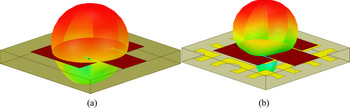
The experimental results show a small shift in the resonant frequency which may be attributed to the fabrication tolerances. Finally, the radiation characteristics of the proposed structure are obtained and compared with the radiation characteristics of the conventional MSA printed over an FR4 dielectric substrate of dielectric constant 4.4, thickness 3.2 mm, and loss tangent tanδ = 0.02 to examine the effect of absorbing layer on the radiation characteristics of the antenna. The radiation patterns are shown in Fig. 7. As seen, the radiation pattern of the proposed structure shows a decrease in gain, beamwidth, and also a significant decrease in the back-lobe radiation. The gain reduces by 6.58 dB, and the beamwidth also reduces by 12.82°. Essentially, the radiation characteristics of MSA are greatly influenced by the size of the ground plane, and a finite ground plane increases the back-lobe radiation. However, the proposed technique reduces the back lobe significantly even for an MSA printed on a finite ground plane. Hence, the proposed technique may be a viable solution to reduce the beamwidth and side lobes even by employing a single element of MSA, of course at the cost of reduced gain.
Radiation characteristics of the (a) conventional MSA, (b) proposed structure.

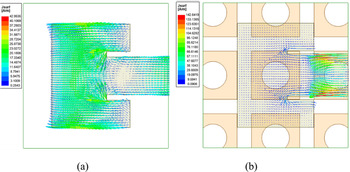
Moreover, the reduced gain may be compensated by transmitted power. The decrease in radiation can further be elaborated by analyzing the current distribution over the radiating patch for the two cases as shown in Fig. 8. As seen in Fig. 8(b) the proposed structure limits the radiation from the patch due to the presence of the absorbing layer beneath the patch as compared to the radiation from the patch of a conventional MSA.
Current distribution over the patch for the (a) conventional MSA, (b) proposed structure.

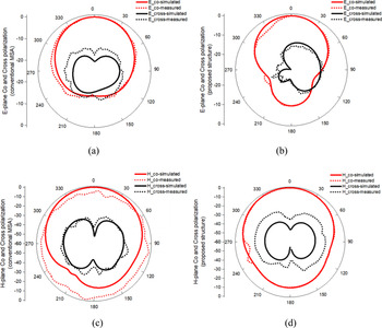
Further, the 2D radiation patterns of the conventional and the proposed antenna structures are presented in Figs 9(a)–9(d) to examine their co- and cross-polarization characteristics. As seen in the figure, the amplitude of the co-polarization component of the proposed structure is reduced significantly in both E- and H-planes without deteriorating the cross-polarization. The characteristics of the gain and radiation efficiency are shown in Figs 10(a) and 10(b). A significant reduction in gain and radiation efficiency are depicted over the entire range of frequencies for the proposed structure.
(a) and (b) Simulated and measured co- and cross-polarized radiation patterns for the conventional MSA, and proposed structure in E-plane. (c) and (d) Simulated and measured co- and cross-polarized radiation patterns for the conventional MSA, and proposed structure in H-plane.

Comparison of (a) gain and (b) radiation efficiency of the conventional MSA, and proposed structure.

Conclusion
The effect of the absorbing layer below the MSA is investigated in this study. The absorber and the proposed structure are analyzed through simulation as well as the experiment. The results depict a decrease in the total radiation from the MSA as all the three parameters of the MSA the gain, beamwidth, and back radiation are reduced. This study may be useful in suppressing both forward and backward radiated emission from high-speed circuits by placing an FSS-based absorbing layer below the existing circuit board.
 Ashish Raj was born in Ranchi, India in 1991. He received the Master's degree in Electronics and Communication Engineering from Gandhi Institute of Technology and Management, Visakhapatnam, India in 2016. He is currently pursuing a Ph.D. in Electronics and Communication from Birla Institute of Technology, Mesra, Ranchi, India. His research interests involve Electromagnetic Compatibility, absorber and its applications in high frequency circuits.
 Nisha Gupta received the Bachelor's and Master's degrees in Electronics and Communication and Electrical and Electronics Engineering both from Birla Institute of Technology, Mesra, Ranchi, India. She pursued her Ph.D. degree from Indian Institute of Technology, Kharagpur, India. She was a post-doctoral fellow at University of Manitoba, Canada from 1997 to 1998 before joining the Department of Electronics and Communication Engineering, Birla Institute of Technology in 1999 as an Associate Professor. Currently, she is a Professor in the same department. She has authored and co-authored more than 150 technical journal articles and conference papers. Her research interest is Antennas, Computational Electromagnetics, AI techniques in Wireless and Mobile Communication, and EMI/EMC.