Introduction
The work described in this document is concerned with a European Space Agency (ESA) Advanced Research in Telecommunications Systems (ARTES AT) project called COLD (‘Compact On-board L-band Diplexers for high-power applications’, ESA Contract Number: 4000120093/17/NL/NR). The main goal of COLD project is the design and development of a very compact Tx/Rx diplexer for satellite mobile applications in L-band where a minimum power-handling of 100 W Continuous Wave (CW) has to be ensured at the Tx channel. First experimental results of Tx and Rx L-band bandpass filters are shown in this paper together with the preliminary measured results of the diplexer.
The current state of the art for telecommunication satellite input and output filters consists of complex bulky networks based on multiple units connected in series. Usually these filters are based on standard technologies such as coaxial circular or rectangular waveguide cavities. Such solutions allow for good performance in terms of insertion loss, power-handling, and spurious-free stop-band ranges. However, these standard approaches provide bulky and heavy geometries going against the communication market key drivers where compact and lighter structures are required. The challenge of reducing the mass/footprint of the filter in space applications has been a very hot topic since last decades, for this reason the effort in the design of compact microwave filters has been notably increased. In [Reference Snyder, Mortazawi, Hunter, Bastioli, Macchiarella and Wu1, Reference Snyder, Macchiarella, Bastioli and Tomassoni2], the trend of the filter development is summarized and several interesting aspects are analyzed. The employment of high-order degenerate modes is a very interesting idea to keep high Q-factor values minimizing the total dimension of the filter. In [Reference Wang, Jang, Lee and Park3], a quad-mode coaxial resonator is proposed where 4th and 8th order filters are designed and measured. Among these solutions, the most common refers to the use of TM multi-mode structures, which achieve a very good compromise between size reduction and unloaded Q-factor. In [Reference Bastioli, Tomassoni and Sorrentino4–Reference Pelliccia, Tomassoni, Cacciamani, Vallerotonda, Sorrentino, Galdeano and Ernst6], waveguide filters, based on resonating and non-resonating TM dual-mode cavities, are presented emphasizing the excellent Q-factor and the compactness of the structure. In [Reference Snyder, Mortazawi, Hunter, Bastioli, Macchiarella and Wu1], dielectric loaded resonator (DR) filters based on high permittivity materials are also mentioned as a valid alternative to standard filters with the advantage of size reduction. The employment of such dielectric filters can be extremely convenient in satellite communications, an example is in [Reference Singh, Parikh, Singh and Bavaria7] where the design of an Output Multiplexer (OMUX) based on TE dielectric loaded resonators is described. The TE01δ mode dielectric resonator filters are an additional example of compact devices which can be used in an extreme environment where low losses and electrical discharge handling capability are required. However, their foremost limitation is the thermal management, made complex due to a low dissipation of the power. This limiting factor is presented in [Reference Yu8], the field is strictly confined in the dielectric pucks, causing an important amount of power concentrated in the DR material and consequently an increment in temperature which can severely compromise the proper working of the device. In addition to TE01δ and TM, another popular (dual-mode) resonator is the HE11 [Reference Fiedziuszko9, Reference Zaidi, Naeem and Shah10] which is still a higher order mode resonator. In HE11 mode, the coupling between the two degenerate modes of the single resonator is obtained by using screws positioned at 45°, while the coupling between modes in different cavities is provided by means of selective polarization slots. Filters based on HE11 mode are widely used also in satellite communication systems.
In [Reference Kobayashi and Yoshida11–Reference Kobayashi and Furukawa13], a detailed discussion about filters based on TM010 mode and loaded with shielded dielectric rod resonators is proposed, while in [Reference Ishikawa, Hattori, Andoh and Nishikawa14], a bandpass filter for base station applications with very high Q-factor and compact size is described. While providing a good performance with an even more reduced size (with respect to TE dielectric mode), TM dielectric resonator presents some technical issues to deal with if used in the extreme environmental conditions typical of the space applications. Several publications on these filters for terrestrial applications have been produced in the past years, an example is [Reference Höft and Magath15] where a diplexer based on TM010 dielectric loaded filter is proposed for base-stations. One of the critical aspects concerning DR is that a soldering process or a support is required to properly bind the dielectric element to the inner wall of a waveguide cavity. This should affect as less as possible the resonant mode of the resonator structure, thus avoiding any exceeding loss due to the connection.
In [Reference Shukla, Shrivastava and Trivedi16], a specific epoxy application for the DR assembly is studied, underling the main risks of this process and the possible advantages in loss reduction. Related to this aspect, the main issue of TM010 dielectric filter is the necessity of a good contact between the top/bottom surfaces of the cavity with the top/bottom faces of the dielectric cylinder which loads the cavity. The different Coefficients of Thermal Expansion (CTE) of the metal enclosure and the ceramic dielectric provide a small detachment of the two materials at their interfaces generally at high temperatures. A small gap of few microns is enough to modify the boundary conditions of the structure and deteriorate the response of the filter. Some patents [Reference Yamakawa and Ishizaki17–Reference Mishra, Biswas and Srivastava21] have already been filed to solve that well-known problem. The filters proposed in this paper are based on TM010 mode dielectric resonators. In this scenario, an effective mechanical design concept has been used to ensure a good contact between the ceramic elements and the cavity. In addition, preventive actions have also been added in order to minimize the high-power undesired phenomena that could occur.
The improvement in power-handling of dielectric resonators is another important aspect to be evaluated since the specifications regarding the Tx channel require a maximum RF input power of 100 W. A detailed description of the most critical phenomena which can occur in filters for high power-handling capability applications is presented in [Reference Yu8]. Some technical design guidelines can be found in literature, as in [Reference Tang and Kudsia22], to limit the effectiveness of this problematic aspect which affects the performance of the electronic device. About this topic, an interesting investigation on the fringing field effect related to the multipactor is proposed in [Reference Wolk, Vicente, Hartnagel, Mattes, Mosig and Raboso23]. Several design approaches can be followed to improve the multipactor of passive filters and most of them consider the enlargement of internal distances and gaps, without compromising the electrical performances of the component. In [Reference Snyder and Bastioli24, Reference Bastioli, Snyder and Jojic25], the designs of filters for high-power applications based on evanescent mode are presented, while in [Reference Pereira, Boria, Gimeno, Rebenaque, Garcia, Melcon, Gonzalez, Schmitt, Raboso, Ernst and Carpintero26] some techniques to reduce the risk of multipactor and alternative waveguide filtering structures are described. An additional example is in [Reference Maiarelli and Mizzoni27] where improvements in terms of multipactor are obtained by introducing dielectric material in the area of discharge. A low-loss polymeric material is employed for filling the critical gap of the coaxial resonators, thus improving the mechanical stability over temperature of the structure, but also increasing the dielectric strength in the most critical region. In this way, the operating power of the filter can reach 150 W CW and 1500 W peak without multipactor discharge phenomena. As described in [Reference Panariello, Yu and Ernst28], there are other fundamental aspects to be considered when dealing with high-power RF devices, one of these is the PIM (Passive Inter-Modulation). PIM is a non-linear phenomenon due to defects in the manufacturing or in the assembly of an RF device (e.g. thin oxide layers and non-ideal contact between metals). Such non-linearity acts like a mixer, generating new signals whose frequency can fall within the desired signal bandwidth causing interference that can severely influence the proper working of a telecommunication system. Several books devoted to the RF design and analysis provide advices to avoid PIM, an example is in [Reference Schettini29–Reference Vicente and Hartnagel31] where some precautions are suggested.
Regarding the filters proposed in this paper, the solution based on TM010 mode dielectric resonators has already been widely used in terrestrial application [Reference Höft and Magath15] where the thermal stability is less critical. Because the advantages of this type of DR are well known, the challenge is to adopt this technology also in space environment. The TM010 mode dielectric resonators employment was already successfully validated by the authors of this document for low-power applications in the L and S bands [Reference Pelliccia, Cacciamani, Sorrentino, Vitulli, Steffè, Diaferia and Picchione32, Reference Pelliccia, Cacciamani, Tomassoni and Sorrentino33]. Also a high-power diplexer has been recently designed and tested [Reference Pelliccia, Cacciamani, Cazzorla, Tiradossi, Vallerotonda, Sorrentino, Steffè, Vitulli, Picchione, Galdeano and Martìn-Igleasis34] by using this technology in the framework of the same COLD project. With respect to the 3rd order in-line filters designed in [Reference Pelliccia, Cacciamani, Cazzorla, Tiradossi, Vallerotonda, Sorrentino, Steffè, Vitulli, Picchione, Galdeano and Martìn-Igleasis34], in this case, the filters order has been increased and transmission zeros (TZs) have been introduced to satisfy the Tx/Rx filter requirements. In this paper, the development and manufacturing of very compact 6th order elliptic high-power filters based on a preliminary idea introduced in [Reference Pelliccia, Cacciamani, Cazzorla, Tiradossi, Vallerotonda, Sorrentino, Steffè, Vitulli, Picchione, Galdeano and Martìn-Igleasis34] are proposed by using high permittivity (>40) dielectric materials. Particular attention has been devoted to high-power undesired phenomena like multipactor and PIM; therefore, some preventive actions have been added in order to minimize them. Capacitive couplings between the TNC input/output connectors and ridged ceramic-loaded resonators have been proposed thus minimizing any risks of undesired PIM at input RF interface.
TX and RX filters design
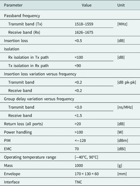
The diplexer requirements are given in Table 1. For both Tx/Rx filters, a 6th order filtering response and a minimum Q-factor of roughly 2500 is required to satisfy out-of-band attenuation and in-band loss requirements.
L-band diplexer requirements

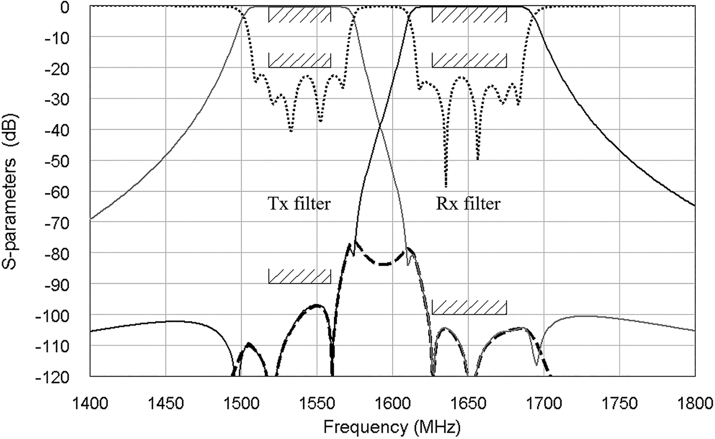
Two TZs in the upper stop-band are used in the Tx filter to fulfil the nearest out-of-band requirements, while in the case of Rx filter, the TZs are placed below the pass-band in order to satisfy the rejection requirements in the Tx channel. In Fig. 1, the desired response of the diplexer obtained by circuital model analysis is shown. Solid lines and dotted lines describe transmission and reflection characteristics (S-parameters) of both filters, respectively, whereas the thick dashed line shows the isolation between the Tx and Rx channels. A frequency margin of 10 MHz on passband edges and isolation frequency has been considered in order to compensate the frequency shifts of the response due to the wide operating temperature range.
Simulated response and mask of the diplexer based on circuital model (solid lines are the transmission characteristics, dotted lines are the reflection characteristics and thick dashed line is the isolation between the Tx and Rx channels).

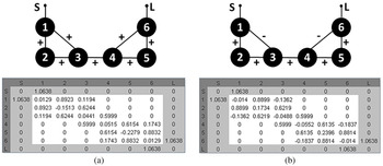
In Fig. 2(a), the topology scheme and the coupling matrix of the Tx filter are shown, while in Fig. 2(b), the topology scheme and coupling matrix of Rx filter are presented.
Tx (a) and Rx (b) filters topology scheme and coupling matrices.

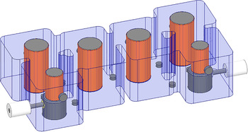
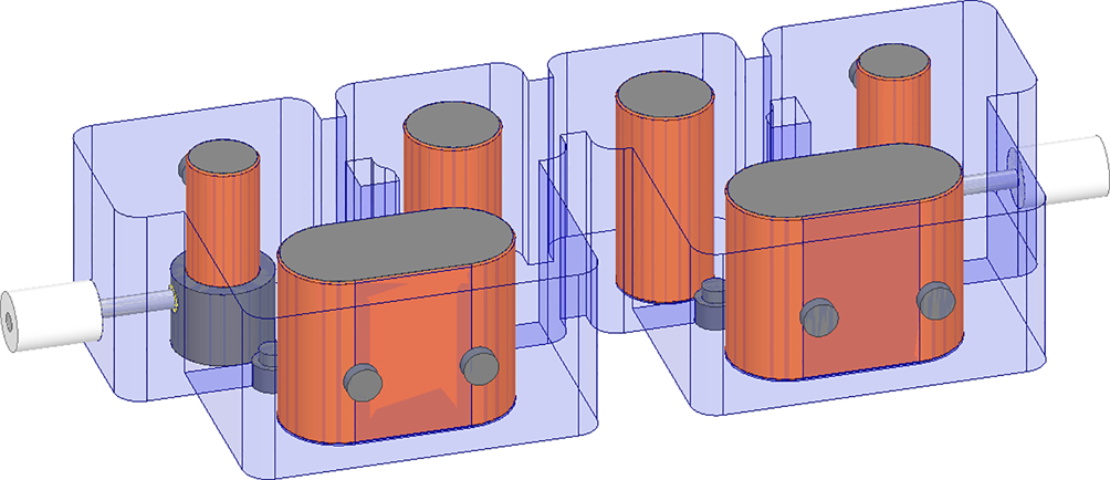
Two positive cross-couplings are required in the Tx filter to obtain two TZs in the upper stop-band whereas two negative cross-couplings are necessary in the Rx filter to generate two TZs in the lower stop-band. The 3D models of Tx and Rx filters are shown in Figs 3 and 4, respectively. These have been designed by using the ANSYS HFSS software. A dielectric material with a dielectric constant of 45 and a Qxf of 48.000 has been used in both designs. Concerning the Tx filter, it is based on six TM010 mode dielectric resonators all coupled by inductive irises.
3D filter model of Tx filter.

3D filter model of Rx filter.

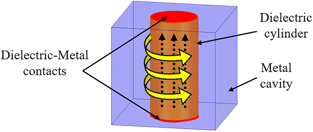
A schematic representation of the electric (E) and magnetic (H) fields inside the resonator is depicted in Fig. 5.
3D model of a TM mode dielectric loaded resonator with E and H field behavior of the TM010 resonant mode (thin dotted arrows are E-field and thick circular arrows are H-field).

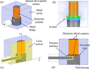
In order to improve high-power performance in terms of power-handling, multipactor and PIM, according to Fig. 6, in the first and last resonators, a ridged geometry has been used. This means the first and last cavities are not pure TM010 resonators but can be defined as quasi-TM010 ridged resonators. In addition, the ridged input/output ceramic-loaded resonators allow for improving the spurious-free range (even if not required in this case). In Fig. 6, the 3D model of the first and last resonators is shown together with the E-field distribution. In Fig. 6(c), the cross-section of the proposed resonator is depicted in order to show further details. A thin housing on the top surface of the metal ridge has been designed in order to minimize alignment errors of the dielectric element inside the cavity during the assembly process. The same solution has been used also for the pure TM010 resonators by including housings in the cavity bottom surfaces. As highlighted in Fig. 6(d), the top edge of the ridge has been smoothed in order to minimize the concentration of E-field in this area improving the RF performance. Concerning the PIM aspect, generally the most critical parts of the filters are the soldered parts and the non-pure metal-metal contacts. For this reason, the proposed solution adopts contactless capacitive couplings. These ones are based on thin polymer interfaces between input metal connectors and resonators as is presented in Fig. 6.
Quasi-TM010 ridged external resonators model: (a) 3D view; (b) E-field behavior; (c) cutting plane reference; (d) cross-section view.

As highlighted in Fig. 5, in order to obtain the desired RF behavior of the resonators, it is important to ensure a stable contact between the dielectric cylinder and the metallic surface of the cavity. The main issue of TM mode dielectric loaded filters is their poor mechanical stability over temperature due to the different CTE of the metal and dielectric ceramic parts. In this scenario, an in-house and effective mechanical design concept based on TM010 mode dielectric resonators has been developed with Thales Alenia Space Italia (partner in the project consortium). This is based on a customized and optimized mechanical and assembly procedures for ensuring the necessary thermal stability of the filter response and RF performance in the whole thermal operating range. The external filter case material has been carefully chosen in order to minimize the CTE difference between the metal cavity and the ceramic elements (CTE roughly 8 ppm/°C). In order to further improve the contact between the metal and dielectric materials, the top and bottom surfaces of each ceramic cylinder have been metallized by employing silver-plating process.
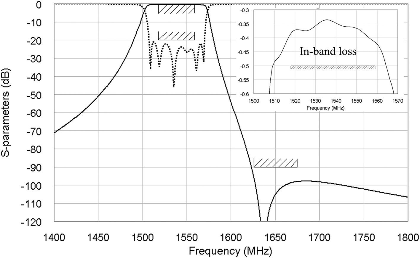
In Fig. 7, the full-wave RF response of the Tx standalone filter is shown together with the desired mask.
Full-wave simulated response of the L-band Tx filter with in-band losses details and mask (solid line is the transmission characteristic, dotted line is the reflection characteristic).

All in-band requirements are fulfilled. A wider passband is obtained according to the circuital model synthesis. Rejection requirements are also satisfied, and rejection will further increase when the filter is used in the diplexer.
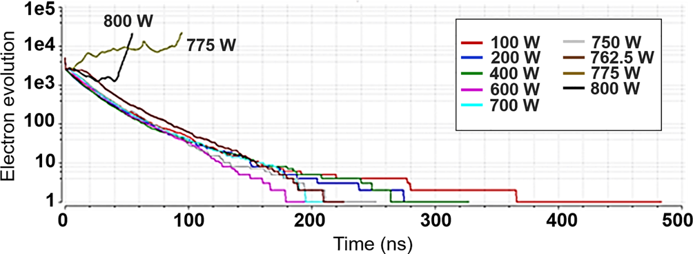
The results in terms of multipactor, PIM, and thermal stability are expected to be compliant with respect to the requirements. Regarding the multipactor, in Fig. 8, the SPARK-3D simulation results carried out on the Tx filter are depicted. The discharge occurs at roughly 768 W (roughly 8.85 dB of margin with respect to the specification of 100 W).
Results of SPARK-3D simulation carried out on the Tx filter.

The 3D model of the Rx filter is shown in Fig. 4. As can be seen, its architecture is similar to that used for the Tx filter. In this case, negative cross-couplings are required for obtaining TZs in the lower stop-band. There are different ways to obtain a capacitive coupling in cavity filters. The most common is the introduction of a probe between two adjacent resonators instead of an inductive iris. This solution is widely used even in TM010 filters, however a different approach has been adopted here. As is shown in Fig. 4, the second-order mode instead of the fundamental one can be exploited by using a non-circular-shaped dielectric with roughly a double width with respect to a cylinder one.
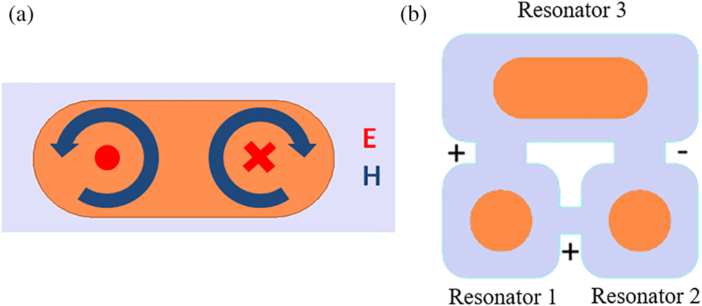
In Fig. 9, the electromagnetic field distribution in the non-circular dielectric resonator is shown together with an example of triplet where the negative coupling is obtained thanks to the different sign of the electromagnetic field at the two ends of the larger cavity.
(a) H- and E-field resonant mode in the second-order mode TM cavities proposed for Rx filter. (b) Negative triplet with a second-order resonator.

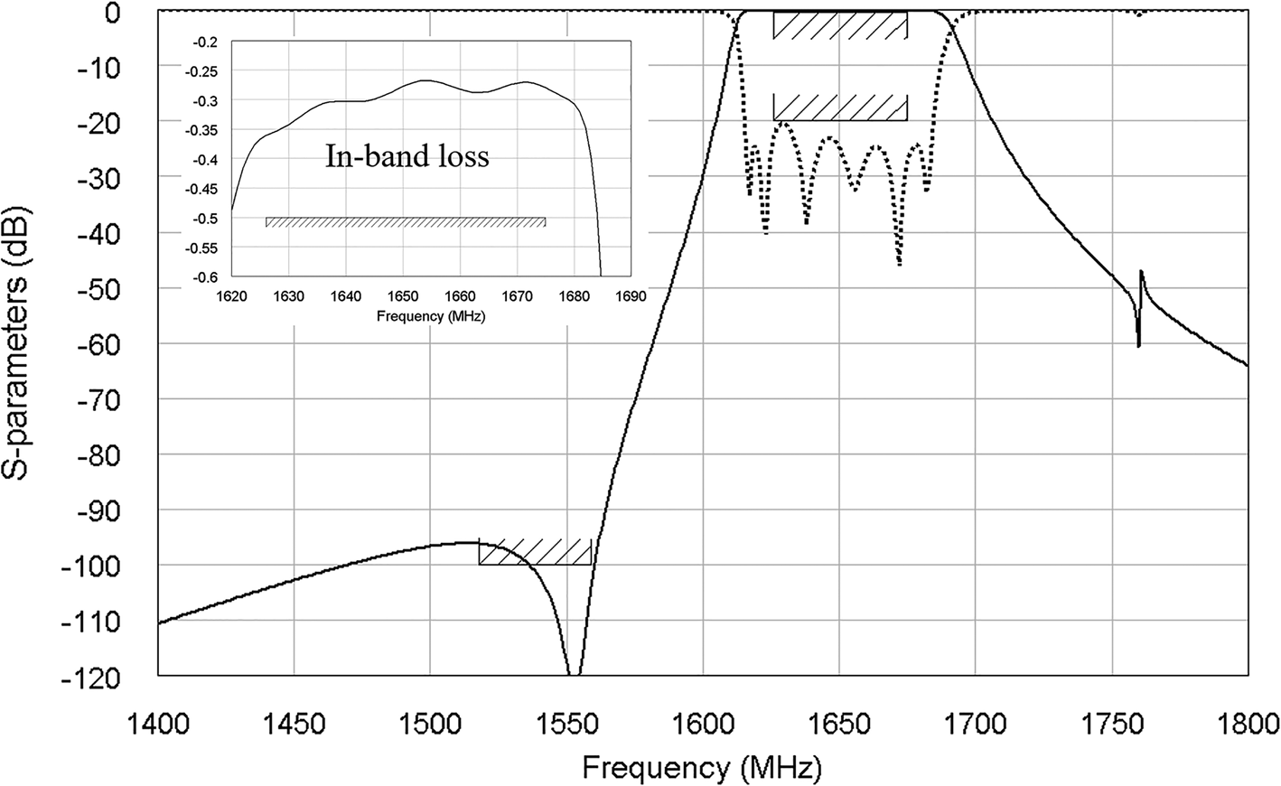
The main advantage of this approach is that no additional parts need to be introduced in the manufacturing and the couplings are all based on simple irises. The simulated response of the Rx standalone filter is shown in Fig. 10. The rejection in the Tx band is slightly lower than that of the requirement, and it will be further increased when the filter will be integrated in the diplexer. In the upper stop-band, an undesired spike appears due to the spurious mode of larger cavities. Thanks to the reduction of the height of these cavities, the spike has been moved from 1.68 to 1.76 GHz. Also in this case, all in-band requirements are satisfied, the RL is higher than 20 dB all over the passband while an IL lower than 0.5 dB is obtained. The out-of-band requirement in terms of attenuation is instead not completely fulfilled. However, this happens in correspondence to the Tx band. This means that an improvement of the attenuation is expected when the filter is assembled in diplexer configuration.
Full-wave simulated response of the L-band Rx filter with in-band losses details and mask (solid line is the transmission characteristic, dotted line is the reflection characteristic).

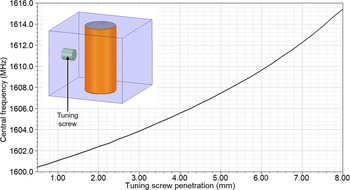
A preliminary tolerance analysis with respect to the most critical parameters has been carried out in both Tx and Rx filters on the base of expected tolerances declared by ceramics and mechanical model suppliers. According to this analysis, tuning screws on cavities and coupling irises have been added in order to compensate the estimated response variation due to the manufacturing tolerances. In Fig. 11, the frequency variation of the TM010 resonant mode is plotted with respect to the tuning screw penetration inside the cavity. A frequency variation of roughly 12 MHz is obtained by increasing the screw penetration from 1 to 7 mm. This frequency shift was initially assumed to be enough to compensate the response variation due to the manufacturing tolerances declared by the manufacturers of metal and ceramic parts. This is actually enough for compensating the manufacturing tolerance of the resonator of Fig. 11 but it is not sufficient for the non-circular-shaped dielectric resonator of Fig. 9(a). The frequency variation can be further improved by increasing the screw penetration at the expense of a worse Q-factor value. In addition, in the high-power Tx filter, an increase of the screw depth implies a minimization of the air gap between the screw head and the ceramic cylinder. This increases the risk of multipactor discharge.
Single TM mode dielectric loaded resonator: 3D model with tuning screw and variation of central frequency with respect to the tuning screw penetration inside the cavity.

Diplexer design
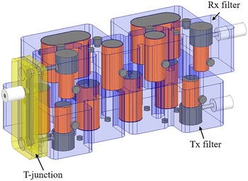
The Tx and Rx filters have been combined together in the diplexer where a custom T-junction has been designed. The 3D model with Tx filter and Rx filter assembled in a stacked configuration is shown in Fig. 12. The Tx filter has been placed below the Rx in order to be closer to the fixing plane so as to help the thermal flowing to the external environment.
3D model of high-power L-band diplexer.

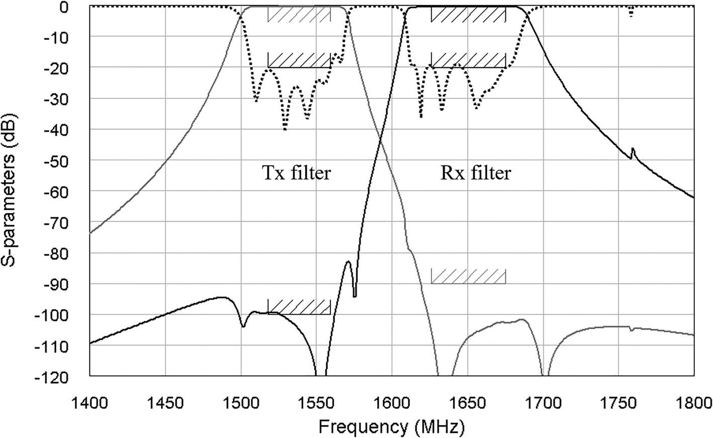
TNC connectors with low-PIM levels have been used. Concerning the T-junction, contactless capacitive couplings have been adopted in order to avoid metal-to-metal contacts thus improving the PIM performance. The simulated response of the diplexer is shown in Fig. 13 where the filters have not been further optimized to improve the response of the diplexer; however, all in-band and out-of-band requirements are fully compliant with the specifications. As expected, the spike positioned roughly at 1.76 GHz due to the unwanted mode of larger loaded-cavities is still present, but it is very weak.
Simulated full-wave response of the diplexer with mask.

Results
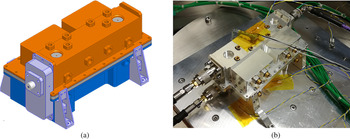
In Fig. 14, mechanical and manufactured models of the diplexer are shown. The final dimensions are 85 mm × 170 mm × 65 mm (W × L × H), whereas the mass is roughly 1060 g, very close to the target (see Table 1).
Mechanical model (a) of L-band diplexer and a picture of the manufactured prototype (b) inside the thermo-vacuum chamber.

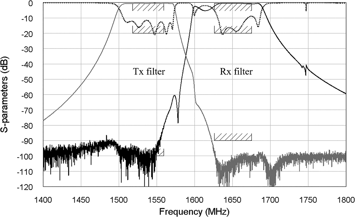
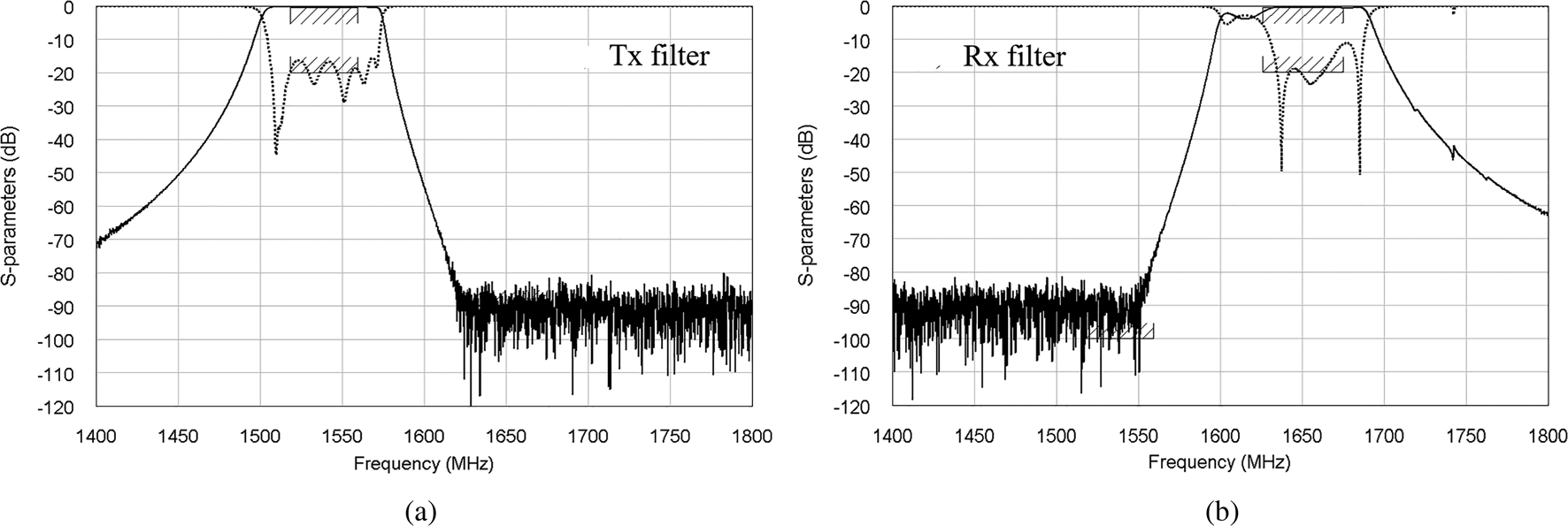
Venting holes have been added on the ridge of the first and last external resonator for allowing a proper depressurization of the volume around the pin and coating. From the electromagnetic point of view, the introduction of these narrow holes does not affect the response. In Fig. 15, the measured response of the diplexer is shown, this can be compared with the measured responses of the standalone filters shown in Fig. 16.
Measured S-parameters of manufactured L-band diplexer with mask (solid lines are the transmission characteristics, dotted lines are the reflection characteristics).

Measured S-parameters with mask of Tx and Rx standalone filters (solid lines are the transmission characteristics, dotted lines are the reflection characteristics).

The responses of both filters are centered roughly at the desired frequency, in particular the Tx filter response where the measured insertion loss is lower than 0.5 dB, it is fully compliant with respect to the specifications. If the response of the Tx standalone filter is considered, the measured Q-factor is roughly 2800, while the Q-factor of Rx filter has not been measured since its response is degraded. The main issue is represented by a pair of poles that are placed at the wrong frequency, this is due to tolerances of non-circular-shaped ceramics elements that are much worse than the values declared by the manufacturers. If the measured response of the diplexer is considered, the Tx isolation on Rx path is widely compliant while the isolation of the Rx filter on Tx channel is hard to be evaluated because of the poles that are out-of-band and the consequent larger bandwidth. A return loss degradation with respect to the standalone filter measurement is observed especially on the Tx filter. The RL issue can be ascribed to a wrong phase matching between simulation and measurements, in particular a phase mismatching between simulation and measurements of the phases of T-junction branches and input couplings of the filters has been observed.
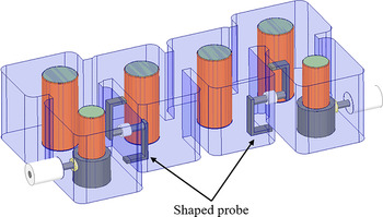
Since it is impossible to recover the in-band Rx response by using the tuning screws, additional approaches can be proposed as an alternative to non-circular ceramic elements. In Fig. 17, an approach based on shaped probes is used. Multiple analyses on alternative solutions are ongoing where additional improvements concerning the T-junction are also analyzed.
Rx filter example with negative couplings based on shaped metal probes.

Considering the current measured Rx filter model in Fig. 4, it could be possible to improve the tuning capabilities by using customized tuning screws. In particular, mushroom-shaped heads of the screws inside the cavity could be used for increasing their capacitance. In this case, the tuning screws can be inserted from inside the cavity before brazing the dielectric elements.
Conclusion
Preliminary experimental results of Tx and Rx L-band bandpass filters for a high-power satellite diplexer have been presented in this paper in the framework of an ESA ARTES AT project called COLD (‘Compact On-board L-band Diplexers for high-power applications’, ESA Contract Number: 4000120093/17/NL/NR). Both Tx and Rx filters are based on 6th order elliptic characteristics where TM010 mode dielectric-loaded resonators have been used. With respect to other standard L-band filters based on coaxial cavity resonators, the compactness and mass reduction are compatible with the goal of the project. In particular, the TM010 mode dielectric-loaded resonators allow to reach a volume saving above 30%. The filter geometries and materials have been chosen in order to improve the power-handling and to cope with related critical issues for space applications (multipactor and low-PIM). The Tx filter shows good correlation with the design in terms of central frequency, bandwidth, and Q-factor that is almost 3000. However, the Rx filter shows a worse correspondence with the design in terms of filter response shape. This is ascribed to size tolerances of one of the filter resonators. Multiple analyses are ongoing to remove this degradation in the final engineering model. Also thermal and high-power tests will be performed once the second prototype will be finalized in order to validate its use in the reference ARTES project (COLD).
Acknowledgements
The diplexer presented in this document is the outcome of the ESA ARTES AT project called COLD (ESA Contract Number: 4000120093/17/NL/NR). Staff from ESA ESTEC (in Noordwijk, The Netherlands), from Thales Alenia Space Italy (in Rome, Italy) and the University of Perugia (in Perugia, Italy) are gratefully acknowledged for their contributions and support. This work is dedicated to the memory of Prof. Roberto Sorrentino. He was an educator, an innovator, and an excellent microwave expert. His dedication to work, honesty, and integrity will always be an inspiration for his former students and colleagues toward excellence.
 Paolo Vallerotonda was born in Umbertide, Italy, in 1985. In 2014, after he worked in Thales Alenia Space Italy for over one year as an RF engineer, he received his Master Laurea degree in Electronic Engineering from the University of Perugia (Italy). Between the years 2014 and 2016, he worked at NPLUST Semiconductor Application Center in Perugia as a Software engineer where he developed software applications for testing and characterization of System On Chip (SOC), in addition to managing the quality and ICT areas. In the same period, he worked at the Engineering Department of Perugia to design filters for space applications for Thales Alenia Space Italy. Since 2016 he is working at RF Microtech Srl as RF and microwave R&D engineer. Since November 2019 he is also a Ph.D. student at the University of Perugia where his research activity is concerned with ultra-performing microwave filters for satellite and terrestrial applications.
 Fabrizio Cacciamani received the Master Laurea degree in Electronic Engineering from the University of Perugia, Italy, in 2009. In February 2010, he joined the Department of Electronic and Information Engineering (DIEI) of the University of Perugia (Italy) under the advice of Prof. Roberto Sorrentino. From 2011 to 2014, he has collaborated with RF Microtech (spin-off of Perugia University, Italy) in several international research projects concerning RF MEMS, microwave filter, and antenna design. Since 2015 he is working at RF Microtech Srl as RF and microwave R&D engineer.
 Luca Pelliccia received his Ph.D. degree in Electronics Engineering at the University of Perugia with a thesis titled “Tunable and Miniaturized Waveguide Filters for Advanced Communication Systems” under the advice of Prof. Roberto Sorrentino. He is currently working at RF Microtech Srl (where he is an associate member) as Head of the Microwave Filter and Passive Components division. His research and design activities include innovative concepts for compact, tunable, and high-performance filters and diplexers. His research involvement has resulted in the publication of several papers in the proceedings of international microwave conferences and journals.
 Alessandro Cazzorla received the Master degree in Informatic and Telecommunications Engineering from the University of Perugia (Italy) in 2010. In 2016, he received the Ph.D. degree in Microwave Engineering at the Department of Engineering at the University of Perugia under the advice of Prof. Roberto Sorrentino. The research activity was focused on the design of RF-MEMS tunable capacitors in CMOS-MEMS/BiCMOS-MEMS platforms. Electromechanical, electromagnetic, and thermo electromechanical analyses have been demonstrated in several scientific publications as author and co-author. He is actually working as a microwave and electronic engineer at RF Microtech and his research interests include RF modeling and design of RF components/subsystems such as high-Q passives, MEMS-based reconfigurable RF circuits, and their implementation into commercial systems.
 Davide Tiradossi was born in Perugia, Italy, in 1992. In 2016–2017, he carried out his master thesis and internship in Ericsson (Goteborg) on the design of MW matching transition at D-band under the advice of Prof. Sorrentino. He received his Master degree (with merit) in Electronic and Telecommunication Engineering from the University of Perugia in April 2017. Since May 2017 he is working at RF Microtech as RF and microwave R&D engineer in the microwave filter area.
 Walter Steffè received the Master degree in Electronic Engineering from the University of Trieste, Italy in 1990. He joined Thales Alenia Space Italia (TAS-I) in 1991 as a technical staff member of the Antenna Group. Since 2008 he managed several RF Advanced Studies within the RF R&D group of TAS-I. He was involved in the design of microwave components for space-based applications such as microwave filters, antenna feeding networks, array antennas, and others. He was a Principal Developer of software tools for electromagnetic simulations and automated tuning of microwave components. He developed a new numerical method for the medialization of generic electromagnetic structures. The new method was implemented and tested with the development of the EmCAD software.
 Francesco Vitulli received the Electronic Engineering Master degree from the University of Rome “La Sapienza”, Italy in 1989. He joined Thales Alenia Space as MW & RF design engineer. Between the years 1998 and 2011, he worked as Head of Commercial TT&C Equipment Engineering and since 2016 he is the manager of RF Advanced Studies in the CCEL Organization in Thales Alenia Space Italia. He is also the author of more than 25 scientific publications that appeared in international reviews/magazines, in international conference proceedings, in international working group reports, and in books. He won one Finmeccanica/ Thales Alenia Space Innovation prize.
 Elio Picchione received his Bachelor degree in Digital Devices of Transmission from the University of L'Aquila, Italy in 1994, received his university degree (2002) in Telecommunications Engineering at the Polytechnic of Torino, and in 2005 his Master's degree in Electromagnetic Compatibility and Environment Impact of Electromagnetic Fields at Sapienza University, Rome. His thesis being: “EMC Analysis of a Ku-Band Receiver for Satellite Application”. Elio Picchione is employed with Thales Alenia Space Italy, L'Aquila plant where he works in Technology & Qualification department. In the year 2018, Elio Picchione has been nominated Processes Technology Specialist from Thales Alenia Space. The expertise of Elio Picchione is based on wide heritage (26 years) in packaging technologies, RF hermetic package and GaAs/GaN MMIC brazing, seam, laser and electron beam welding, surface treatments NDT, MIL screenings, and DPA on Hi-Rel components, for microwave cavities and hybrid circuits; space qualification according to MIL and ECSS standards.
Jaione Galdeano. Curriculum Vitae unavailable
 Petronilo Martín-Iglesias received the Telecommunication Engineering degree from the Polytechnic University of Madrid, Spain, in 2002 and the Master degree from the University of Leeds, UK, in 2012. He has been working in the industry for more than 15 years as Microwave Engineer for active (high-power amplifiers for radar applications) and passive (filters, multiplexers, couplers, etc.) RF hardware design, including 2 years as Radar System Engineer working for INDRA SISTEMAS, ISDEFE S.A., and Thales Alenia Space Spain. Since summer 2012 he has been working in the European Space Agency following R&D activities related to RF passive hardware (filter synthesis theory, EM design, ferrite-based components, and high-power prediction as well as advanced manufacturing techniques for RF passive hardware). He has also provided support to projects such as MetOp-SG Scatterometer (particularly for the RF front-end), BIOMASS (high-power aspects), or ELECTRA among others.
 Cristiano Tomassoni received the Ph.D. degree from the University of Perugia, Italy, in 1999. In 1999, he was a Visiting Scientist with the Lehrstuhl für Hochfrequenztechnik, Technical University of Munich, Germany. In 2001, he was a Guest Professor with the Fakultät für Elektrotechnik und Informationstechnik, Otto-von-Guericke University, Magdeburg, Germany. Since 2007, he is with the University of Perugia. He is an expert on miniaturized filters, reconfigurable filters, dielectric filters, and 3-D printed filters. Dr. Tomassoni is a member of the MTT-5 Filters Technical Committee. He received the Best Paper Award (Second Place) at the International Conference on Numerical, Electromagnetic and Multiphysics Modeling and Optimization (NEMO2018) and the Best Paper Award (First Place) at the 15th Mediterranean Microwave Symposium (MMS2015). He was a recipient of the 2012 Microwave Prize presented by the IEEE Microwave Theory and Technique Society. He is currently an Associate Editor of the IEEE Transactions on Microwave Theory and Techniques.