I. INTRODUCTION
Recently, Co-base alloys with a γ/γ′-microstructure similar to that of Ni-base superalloys were discovered. Reference Sato, Omori, Oikawa, Ohnuma, Kainuma and Ishida1 In these Co-base alloys, a face-centred cubic (fcc) solid solution of Co, γ, is strengthened by precipitation of a stable ternary Co3(Al,W) intermetallic compound, γ′, with the ordered structure L12 (Cu3Au type). It is assumed that these new γ′-strengthened Co-base alloys can substitute the Ni-base superalloys in some important applications. The reasons for this assumption are:
-
(i) The discovered Co-base alloys have higher solidus and liquidus temperatures compared with those of Ni-base superalloys, which makes them potentially attractive for high-temperature applications.
-
(ii) These Co-base alloys have good castability due to the narrow solidification interval and a low degree of segregation during solidification. This is important for manufacturing of the large single-crystal blades needed for power gas turbines.
-
(iii) These Co-base alloys are γ single phase in a wide temperature interval, and the material is then soft and ductile. This could permit high-temperature processing, e.g., forging or rolling, assuming that these alloys could be developed as wrought or sheet materials.
Research activities on these new Co-based alloys include: alloy development, Reference Sato, Omori, Oikawa, Ohnuma, Kainuma and Ishida1–Reference Petrushin, Hvatzkiy, Gerasimov, Link, Epishin, Nolze and Gerstein7 mechanical testing, Reference Pollock, Dibbern, Tsunekane, Zhu and Suzuki2–Reference Titus, Suzuki and Pollock8 testing of structural stability Reference Lopez-Galilea, Zenk, Neumeier, Huth, Theisen and Göken9,Reference Epishin, Petrushin, Link, Nolze, Loshchinin and Gerstein10 and oxidation, Reference Pollock, Dibbern, Tsunekane, Zhu and Suzuki2,Reference Klein, Bauer, Neumeier, Görken and Virtanen11 and investigations of deformation micromechanisms. Reference Suzuki and Pollock3,Reference Pyczak, Bauer, Göken, Neumeier, Lorenz, Oehring, Schell, Schreyer, Stark and Symanzik12–Reference Eggeler, Müller, Titus, Suzuki, Pollock and Spiecker15 At the current stage of alloy development, several Co-base alloys have been proposed, which have creep strengths at temperatures 800–900 °C approaching those of Ni-base superalloys, e.g., Refs. Reference Suzuki and Pollock3–Reference Bauer, Neumeier, Pyczak and Göken5.
An interesting feature of new γ′-strengthened Co-base alloys is that the γ/γ′-lattice misfit in these alloys is significantly shifted toward the positive side. For example, in the experimental alloy Co9Al9W0.1B, the “constrained” γ/γ′-misfit (i.e., misfit between the spacings of constrained γ- and γ′-lattices measured in undeformed material) was found to be +0.8%. Reference Pyczak, Bauer, Göken, Neumeier, Lorenz, Oehring, Schell, Schreyer, Stark and Symanzik12 For comparison, the misfit in the widely used superalloy CMSX-4 is of about −0.25%. Reference Brückner, Epishin and Link16 Such a big difference between the misfit in the Co- and in Ni-base alloys results from a difference in the partitioning of the elements between the γ- and γ′-phases. As follows from, e.g., Reference Sato, Omori, Oikawa, Ohnuma, Kainuma and Ishida1–Reference Petrushin, Hvatzkiy, Gerasimov, Link, Epishin, Nolze and Gerstein7 elements like Mo, W, Re, although being the matrix elements in Ni-base alloys, in Co-base alloys have a preference to partition into the γ′-phase, by this increasing its lattice spacing more than in the Ni-base. The finding of a positive misfit in Co-base alloys reopens the discussion about the importance of sign and magnitude of γ/γ′ lattice misfit in superalloys, see Mughrabi. Reference Mughrabi17 Clarification of this question will need theoretical investigations, e.g., similar to Ref. Reference Gao, Fivel, Ma and Hartmaier18, as well as the misfit-relevant experiments. This article presents such an experimental contribution.
The alloy under investigation in this work is a γ′-strengthened Co-base alloy with zero γ/γ′-lattice misfit that was developed recently at the VIAM, Moscow. The points of interest are the deformation behavior, structural behavior, and deformation mechanism of this superalloy at the initial stage of creep at 800 °C under a load of 196 MPa.
II. EXPERIMENTAL
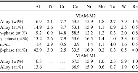
The alloy under investigation was an experimental Co-base alloy VIAM-M2 (M: Multicomponent) developed at the VIAM in Moscow, with composition as given at the top of Table I. It is seen from Table I that this alloy contains a high concentration of Co, 53.1 at.%, and the sum of the concentrations of Co and another basic element, Ni (15.9 at.%), is 69 at.%, which is typical for Ni-base superalloys. Concentrations of other alloying elements are close to those in Ni-base superalloys. In spite of the compositional and structural (γ/γ′) similarity with Ni-base alloys, the element partitioning in the Co-base alloy essentially differs from that in the Ni-base alloys. It is seen from the results of energy dispersive X-ray (EDX) microanalysis in a transmission electron microscope (TEM), Table I, that typical γ-solid solution strengtheners, W and Mo, have higher concentrations in γ′ than in γ, and Re has significant concentration in γ′ as well, which is different from the element partitioning in Ni-base superalloys, see e.g., Refs. Reference Hemmersmeier and Feller-Kniepmeier19 and Reference Schulze and Feller-Kniepmeier20. Results from previous investigations Reference Petrushin, Hvatzkiy, Gerasimov, Link, Epishin, Nolze and Gerstein7,Reference Epishin, Petrushin, Link, Nolze, Loshchinin and Gerstein10 of the Co-base alloy VIAM-M1, which has similar composition but without Ti and Cr, are used in this work for comparison of the γ′-morphologies. Its composition is given at the bottom of Table I.
Compositions of Co-base alloys VIAM-M2this work and VIAM-M1 Reference Klein, Bauer, Neumeier, Görken and Virtanen11,Reference Pyczak, Bauer, Göken, Neumeier, Lorenz, Oehring, Schell, Schreyer, Stark and Symanzik12 measured by EDX in SEM, and composition of phases γ, γ′ and β in alloy VIAM-M2 measured by EDX in TEMthis work.

Single crystals of the experimental Co-alloy were solidified by the Bridgman method with liquid metal cooling. The crystal orientation was set by a seed placed in the crucible bottom, giving [001] oriented crystal growth. The single-crystal ingots were cylinders of diameter 15 mm and length 185 mm. The deviation of the cylinders’ axes from [001] did not exceed a few degrees. After casting, the ingots were subjected to homogenization (1300 °C/15 h), followed by aging (700 °C/48 h). After heat treatment, the material consisted of a continuous γ/γ′-microstructure and about 10 area% rest eutectics.
-
Magnitudes of the “constrained” γ/γ′-lattice misfit,
 $${\delta _{\rm{c}}} = {{\left( {{a_{\gamma '}} - {a_\gamma }} \right)} / {0.5\left( {{a_{\gamma '}} + {a_\gamma }} \right)}}\quad ,$$
where a γ and a γ′ are the spacings of the mutually constrained γ- and γ′-lattices, which were measured by X-ray diffraction (XRD) using 222 reflections of Fe Kα and 004 reflections of the Cu Kα radiation. The area irradiated by the X-ray beam was about 8 mm2, which covers about 400 dendritic cells, hence the measured misfit value represents the average over the dendritic structure. It was found that δc ≈ +0.27% (average of 0.24 and 0.30%) in the alloy VIAM-M1. In the alloy VIAM-M2, δc ≈ 0% (average of −0.08% and +0.07%).
From the heat-treated ingots of VIAM-M2, cylindrical creep specimens with a gauge diameter of 5 mm and a gauge length of 25 mm were machined. They were tested in a lever arm creep machine under a tensile stress of 196 MPa at 800 °C in air. Two creep tests were performed, interrupted after 500 h and 550 h, respectively, at creep strains of about 1%.
The deformed alloy was investigated by scanning electron microscopy (SEM) and TEM under the aspects of stability of the γ/γ′-microstructure, phase equilibrium, and deformation micromechanisms. The SEM used is a Zeiss LEO GEMINI 1530 VP (Carl Zeiss Meditec, Oberkochen, Germany) equipped with a Bruker x-Flash 5030 detector for EDX microanalysis and an e− Flash HR detector for electron backscatter diffraction (EBSD) with the software Esprit and CrystAlign (Bruker, Berlin, Germany). Specimens for SEM were cut parallel to the longitudinal planes (100), mechanically grinded, and then polished. The final step of preparation was polishing with an emulsion containing 0.25 μm silica powder, necessary to remove the mechanically deformed surface layer, which would distort the EBSD pattern. The TEM used is a Philips CM30 (Philips Electron Optics, Eindhoven, the Netherlands) with an EDX microanalysis system NSS 2.3 from Thermo (Thermo Electron Corporation, Madison, Wisconsin). The TEM foils were cut perpendicular to the specimen axis [001] and then electrolytically thinned in an electropolisher, Struers Tenupol-3 (Struers, Copenhagen, Denmark), with an electrolyte of 10 vol% perchloric acid, 83 vol% ethanol, and 7 vol% glycerine, at −30 °C. Dislocations were observed in a two-beam bright field diffraction contrast, and their Burgers vectors b were determined by the contrast extinction rule gb = 0, where g is the reciprocal lattice vector positioned such that it meets the Bragg condition. The glide plane was determined by orienting it in the edge-on position, so the dislocation gliding on it appears straight.
III. RESULTS
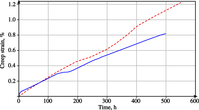
Figure 1 shows creep curves of the alloy VIAM-M2 obtained in two tensile creep tests at 800 °C, 196 MPa, interrupted at a creep strain of about 1%. It exposes that in this strain range, the Co-base alloy deforms with nearly a constant strain rate of about 5.5 × 10⁻⁹ s−1 = 2 × 10⁻³%/h. No transient creep is observed for the first specimen (dashed line); for the second (solid line), one can discern a very small transient creep of about 0.08%.
Creep curves of two [001]-oriented single crystals of the Co-base alloy VIAM-M2 tested at 800 °C/196 MPa.
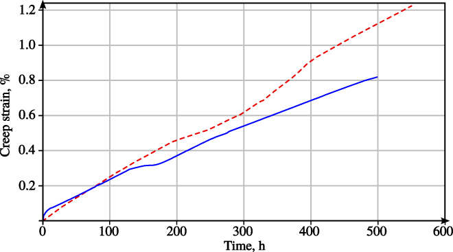
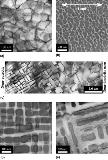
Figure 2 shows the microstructures of VIAM-M2 and, for comparison, VIAM-M1. VIAM-M2 is depicted in the heat treated state [Fig. 2(a)] and after creep [Figs. 2(b) and 2(c)], VIAM-M2 after heat treatment [Fig. 2(d)] and degradation test (stress-free annealing) [Fig. 2(e)]. The temperature of the degradation test was 800 °C, the same as under the creep test on VIAM-M2.
γ/γ′-microstructure of Co-base alloys before and after testing. (a, b, c) Alloy VIAM-M2. (a) After heat treatment, TEM. (b) After creep test (550 h/800 °C/196 MPa), longitudinal cut (100), and SEM. (c) After creep test, cross section (001), and composed TEM image. (d, e) Alloy VIAM-M1, after heat treatment and after a 125 h degradation test at 800 °C, TEM, quoted from Ref. Reference Epishin, Petrushin, Link, Nolze, Loshchinin and Gerstein10.

Comparing the heat treated microstructures of alloys VIAM-M1 with nonzero misfit [Fig. 2(d)] and VIAM-M2 with zero misfit [Fig. 2(a)], it is seen that in the first case, the γ′-precipitates have cuboidal morphology, while in the second case, the γ′-morphology is polyhedral. In both cases, the γ′-precipitates are very fine, and their size is about 100 nm. The γ-channels separating the polyhedral γ′-precipitates in the alloy VIAM-M2 are very narrow, and their width is about 10 nm.
Figure 2(e) shows the γ/γ′-microstructure of the alloy VIAM-M1 after a degradation test (125 h/800 °C), during which it has become rafted even without stress applied. The raft thickness is approximately equal to the initial γ′-size. The stable plate-like γ′-morphology nearly does not change during further annealing at 800 °C up to 1000 h. Reference Epishin, Petrushin, Link, Nolze, Loshchinin and Gerstein10
The structural behavior of VIAM-M2 is totally different. The initial polyhedral γ′-morphology in this alloy is preserved during creep in spite of significant coarsening, see Fig. 2(b). The γ′-precipitates coarsen almost isotropically, and their size after creep scatters around 0.9 μm (equivalent diameter), which means that the γ′ is coarsened by almost 10 times! It is remarkable that in local areas near the eutectic inclusions, the γ′-morphology is clearly cuboidal [see Fig. 2(c), left], which is typical for superalloys with nonzero misfit, but with increasing the distance from the eutectic, the γ′-precipitates become larger and irregular like in most volume of the material. Obviously, such a microstructural inhomogeneity results from gradients in the chemical composition in the vicinity of the eutectic, which is a consequence of dendritic segregation.
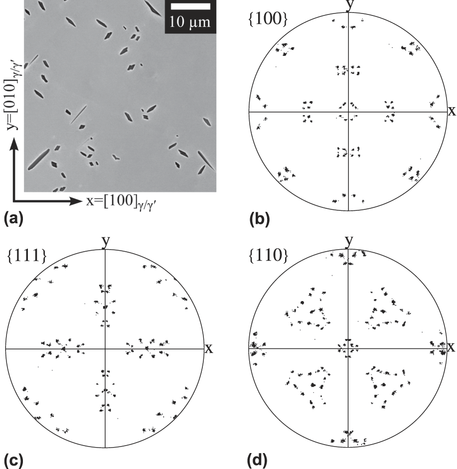
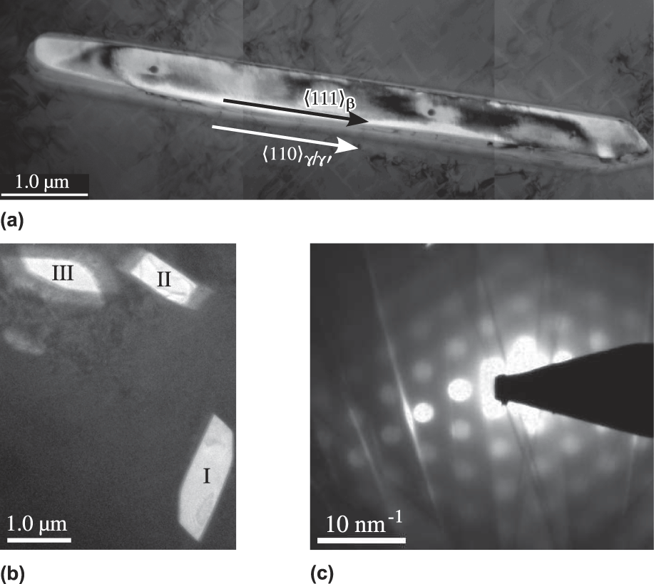
In the alloy VIAM-M2, about 2–3 area% of the needle-shaped phase precipitated in the dendritic arms during creep, see Fig. 3(a). Precipitates of such a morphology were observed in the alloy VIAM-M1 after short tensile tests at 1000 °C, Reference Petrushin, Hvatzkiy, Gerasimov, Link, Epishin, Nolze and Gerstein7 as well as after 1000 h annealing at 800 °C. Reference Epishin, Petrushin, Link, Nolze, Loshchinin and Gerstein10 In Ref. Reference Petrushin, Hvatzkiy, Gerasimov, Link, Epishin, Nolze and Gerstein7, these precipitates were identified in TEM as the β-phase with a crystal structure B2 (CsCl type). In the present work, the needle-shaped precipitates in VIAM-M2 were investigated by EDX in TEM and EBSD in SEM. The TEM investigations confirmed that the observed precipitates are β-phase consisting mostly of Al, Co, and Ni and have a stoichiometry close to Al3(Co2Ni), see Table I.
(a) BSE image of β-needles precipitated in the γ/γ′-microstructure of the Co-base VIAM-M2 alloy after 500 h creep at 800 °C/196 MPa. (b, c, d) {100}β, {111}β, and {110}β pole figures confirming the Kurdjumov–Sachs orientation relationship {111}γ/γ′‖{110}β, 〈110〉γ/γ′‖〈111〉β, EBSD.

The relative orientations of the γ/γ′-lattice and the β-lattices were investigated by EBSD in SEM. Diffraction patterns were acquired from an area of the specimen, where patterns from several β-precipitates could be obtained in addition to those of the single-crystal γ/γ′-matrix. Figures 3(b)–3(d) display the pole figures for the standard projections {100}β, {111}β, and {110}β, which are preferably used as proof for the corresponding orientation relationship between fcc and body-centred cubic (bcc) crystal structures. The shown pole distributions are very close to the orientation-relationship model proposed by Kurdjumov and Sachs Reference Kurdjumov and Sachs21 : {111}γ/γ′‖{110}β, 〈110〉γ/γ′‖〈111〉β. It assumes that close-packed lattice planes as well as directions are parallel to each other. The reference axes x, y, and z are parallel to 〈100〉γ/γ′. Detailed description of the characterization of the fcc/bcc orientation relationship by EBSD is given in Ref. Reference Nolze22.
Figure 3 gives the orientation relationship between the γ/γ′- and β-lattices but not the growth direction of the needle-shaped β-precipitates. Therefore, identification of the axis direction of the β-needles was performed in the TEM, see Fig. 4. To determine the crystallographic orientation of the axes of the β-needles, they were oriented in the upright position (parallel to the electron beam) by tilting the TEM foil. This orientation is recognized by the sharp contour of the needle because the precipitate does not overlap with the matrix. In Fig. 4(b), needle I is in an upright position and needles II and III are not. Figure 4(c) shows the corresponding diffraction pattern of needle I. The 6-fold symmetry of the spot positions in the diffraction pattern indicates that the beam is almost parallel to the 〈111〉 zone axis, which means that the needle axis coincides with the 〈111〉 axis of the β-lattice. The same result was obtained for several analyzed β-needles. Detailed EBSD analysis showed that the [111] needle axis of a β-precipitate is parallel to one of the six 〈110〉 directions of the γ/γ′-matrix.
β-precipitates in the Co-base alloy VIAM-M2 after 550 h creep at 800 °C, 196 MPa (TEM micrographs). (a) Needle lying in the foil’s plane (composite image). (b) Needles passing through the foil, I is in an upright position. (c) Diffraction pattern of needle I.

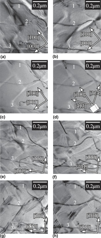
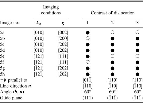
Figure 5 shows TEM micrographs of typical dislocation configurations observed in the alloy VIAM-M2 crept for 550 h at 800 °C and 196 MPa. It is seen from Fig. 5 that dislocations propagate simultaneously in two phases, γ and γ′. These images were used for identification of Burgers vectors
b
, line vectors
u
, and glide planes; the results are presented in Table II. Applying the invisibility criterion
gb
= 0, eight dislocations in Fig. 5 were analyzed. In all cases, Burgers vectors
b
were found to be parallel to crystallographic directions 〈011〉. In Fig. 5(e), the glide plane of dislocations 2 and 3 are in the edge-on position; it is found to be
 $\left( {\bar{1}1\bar{1}} \right)$
. The approximate line vector along the length of dislocations 2 and 3 is
 $\left[ {\bar{1}01} \right]$
. In Fig. 5(f), a part of dislocation 1 resides in a glide plane which is in the edge-on position; it is found to be
 $\left( {\bar{1}\bar{1}\bar{1}} \right)$
, and the line direction is
 $\left[ {\bar{1}10} \right]$
. The glide planes determined by orienting in the edge-on position are in accordance with the plane normal calculated by
b
×
u
. From this, we concluded that dislocations glide on the
 $\left\langle {01\bar{1}} \right\rangle \left\{ {111} \right\}$
glide system, which is typical for fcc crystals. The dislocations are mostly of mixed type, with 60° deviation between
b
and
u
. Observation of large areas of TEM foils revealed neither antiphase boundaries (APBs) nor stacking faults, which could indicate γ′ cutting by partial dislocations. Therefore, it was concluded that the dislocations gliding in γ′ are superdisloactions a〈011〉. A short matrix segment connecting two γ′ dislocations over a narrow γ-channel is assumed to be a couple of a/2〈011〉 dislocations, where splitting is blocked by a strong Orowan force. Entering of the γ-channels by tongue-shaped dislocation loops was observed very rarely, only in local specific areas with the coarse γ/γ′-microstructure.
Dislocation configurations after 550 h creep at 800 °C, 196 MPa used for identification of Burgers vectors, line vectors, and glide planes (TEM micrographs). Images (a-h) present the same area but under different imaging conditions ( k 0 and g ) given in Table II. Note that here, the lattice direction parallel to the stress axis is called [010]. Arrows give the projections of lattice vectors into the image plane. In (d), the orientation of the lattice’s unit cell is indicated by a cube.

Identification of Burgers vectors from dislocation contrasts in the TEM. ● stands for visible and ○ for extinct dislocation contrast. Note that here, the lattice direction parallel to the stress axis is called [010]. Line vectors are only approximate.
IV. DISCUSSION
It was found that the structural and deformation behavior of the Co-base alloy VIAM-M2 with zero misfit significantly differs from that of Co-base and Ni-base alloys with nonzero misfit. After heat treatment, the γ′-phase has a polyhedral morphology. The polyhedral γ′-particles coarsen isotropically during creep without pronounced rafting. The creep curves are linear (constant strain rate) without essential transient creep. The micromechanism of creep is also specific: Dislocation loops do not primarily spread along the matrix channels but just glide simultaneously in both γ and γ′. Although this structural and deformation behavior is quite unusual, it fits well with the parameters of the γ/γ′-microstructure, namely zero misfit and small channel width. This will be shown in the discussion of individual findings in the following four paragraphs.
A. Polyhedral shape after heat treatment
It is known that the cuboidal γ′-shape with {001} faces is stabilized by misfit stresses. This is because the energy of misfit stresses is minimal when the highly stressed γ-channels have {001} orientation. This, in turn, is because the lattice stiffness is minimal along 〈001〉 directions lying in {001} planes. If the γ/γ′-misfit is equal to zero, the γ′-shape is determined by the interface surface tension instead, which should result in a spherical shape. But packing of the equal γ′-spheres is possible only up to 74% volume fraction or even less if the γ-channels between the γ′-precipitates still exist. The γ′-fraction estimated in the alloy VIAM-M2 from its composition is close to 80 vol%, hence, it exceeds the upper critical value. Therefore during γ′-growth, the approaching surfaces of neighboring γ′-precipitates become flat which leads to a polyhedral shape.
B. Coarsening without rafting
It is shown in many publications, e.g., in Refs. Reference Socrate and Parks23 and Reference Nabarro24 that misfit stresses are needed for rafting to take place during creep. When superalloys with a negative misfit are creep deformed under uniaxial stress, a superposition of the applied and misfit stresses acts on the material. When the N-channels (i.e., channels oriented normal to the load axis) undergo plastic deformation, this results in a relaxation of the misfit stresses in the N-channels, which in turn results in the formation of an anisotropic pressure field around the γ′-precipitates. This anisotropic pressure field activates a cross diffusion of alloying elements, resulting in an increase of the width of the relaxed N-channels and narrowing of the stressed P-channels parallel to the load axis. This leads to the change of γ′-shape and finally in coalescence of the neighboring γ′-precipitates, i.e., rafts perpendicular to the load direction. If the γ/γ′-misfit is zero, then no misfit stresses support the applied stress in the N-channels; therefore, no preferable plastification of the N-channels takes place, and finally no driving force for cross diffusion and rafting evolves.
C. Cuboidal γ′-shape near the eutectics
It was shown in Refs. Reference Brückner, Epishin and Link16 and Reference Brückner, Epishin, Link and Dressel25 that segregation of alloying elements in Ni-base alloys during dendritic growth results in inhomogeneity of the γ/γ′-misfit within a dendritic cell. The degree of dendritic segregation depends on the alloy composition and somewhat differs for Ni- and Co-base alloys. However, the segregation character is similar for alloys of these two classes, e.g., in Ni-as well as in Co-base alloys, W segregates into the dendritic arms, while Ta segregates into the interdendritic regions, see e.g., Ref. Reference Lopez-Galilea, Zenk, Neumeier, Huth, Theisen and Göken9. In Ref. 26, quaternary Co–Al–W–Ta alloys were characterized; in particular, the effect of alloy composition on spacing of the γ- and γ′-lattices, a γ and a γ′, was investigated. Fitting of the results gave the following linear equations:
 $${a_{\gamma '}}\left[ {{\rm{nm}}} \right] = 0.35976 + \left( { - 5.1\;{c_{{\rm{Al}}}} + 2.2\;{c_{\rm{W}}} + 26.4\;{c_{{\rm{Ta}}}}} \right) \cdot {10^{ - 5}}\quad ,$$
 $${a_\gamma }\left[ {{\rm{nm}}} \right] = 0.35694 + \left( {3.3\;{c_{{\rm{Al}}}} + 17.1\;{c_{\rm{W}}} - 2.9\;{c_{{\rm{Ta}}}}} \right) \cdot {10^{ - 5}}\quad ,$$
where c i is the concentration of the ith element in at.%.
It’s seen from Eq. (2) that W significantly increases the γ-spacing a γ (preconcentration factor 17.1 × 10⁻⁵ nm/at.%), while from Eq. (3) it can be followed that Ta significantly increases the γ′-spacing a γ′ (preconcentration factor 26.4 × 10⁻⁵ nm/at.%). Taking into account the definition of the γ/γ′-misfit, Eq. (1), one can see that Ta significantly increases the misfit value δc, while W significantly decreases δc. Thus, the average misfit in the alloy VIAM-M2 is close to zero, but in the interdendritic region, it can increase due to higher c Ta, as well as lower c W. This local increase of the misfit is obviously the reason why the γ/γ′-microstructure is cuboidal and not polyhedral in the interdendritic regions of the VIAM-M2 alloy, that is, close to the eutectic, see Fig. 2(c).
D. Constant-rate creep curves and dislocation micromechanism of deformation
Under the testing conditions used, the Co-base alloy VIAM-M2 deforms by the glide of dislocation loops on the 〈011〉{111} glide system, as is typical for fcc crystals. It is remarkable that the dislocation loops glide simultaneously in both γ and γ′, keeping a straight shape when they cross the γ-channels. This is different from the dislocation mechanism observed in Ni-base superalloys with nozero misfit, where creep deformation starts by gliding of the dislocation loops in the matrix channels, see, e.g., Refs. Reference Link, Epishin and Fedelich27–Reference Probst-Hein, Dlouhy and Eggeler29. This primary matrix glide results in a fast transient creep, which then slows down due to a back stress of deposited interfacial dislocations. In VIAM-M2, dislocation loops gliding exclusively in the matrix channels and dislocations deposited in the γ/γ′-interface by the matrix glide were very rarely observed. This suggests that the primary matrix glide was not generally activated in the investigated Co-base alloy, and this explains why transient creep is not observed. There are two obvious reasons for this: First, in an alloy with zero misfit, there is no misfit stress supporting the entering of dislocation loops into the matrix channels. Second, without rafting rapidly widening the matrix channels, the matrix glide can be blocked by a strong Orowan back stress for an extended time, in our case for 500 h. However, at longer creep times, isotropic coarsening will widen the γ-channels, permitting the matrix glide. Such a structural behavior (without rafting) as well as a deformation behavior (without transient creep) was observed in an experimental Ni-base alloy UM-F22 which has γ/γ′-misfit close to zero. Reference Carrol, Feng and Pollock30 During testing at 950 °C and 290 MPa, this alloy showed no rafting and slow creep for 100 h. But after this time, the γ/γ′-microstructure became significantly coarsened, and the creep rate rapidly accelerates. Deformation without the primary matrix glide was reported in Ref. Reference Zhang, Harada, Koizumi and Kobayashi31 for a high-temperature low-stress creep (1100 °C and 137 MPa) of a superalloy TMS-75 with a small lattice misfit. Due to the small value of γ/γ′-lattice misfit, the dislocations could not glide in the matrix channels but mainly climbed around the γ′-cuboids. In our case, such a climbing is not activated due to a much slower diffusion at 800 °C.
γ′ cutting by 〈011〉 superdislocations is a classical mechanism first reported by Kear and Wilsdorf for the L12 structure of Cu3Au Reference Kear and Wilsdorf32 and then reported for Ni-base superalloys many times, see e.g., Ref. Reference Scheumann-Frerker, Gabrisch and Feller-Kniepmeier33. However, this mechanism identified in our work differs from that reported recently for the creep of Co-base alloys at 900 °C. Reference Eggeler, Titus, Suzuki and Pollock13–Reference Eggeler, Müller, Titus, Suzuki, Pollock and Spiecker15 The authors found γ′ cutting by a/2〈011〉 and a/2〈112〉 dislocations, accompanied by the formation of APBs and stacking faults. Here, one should notice that a stress level applied in our case, 196 MPa, is significantly lower than stress levels applied in Refs. Reference Eggeler, Titus, Suzuki and Pollock13–Reference Eggeler, Müller, Titus, Suzuki, Pollock and Spiecker15, between 275 and 345 MPa. It is well known that high stresses are needed to press the partial dislocations inside a superlattice. Moreover, at 800 °C, the temperature of our creep tests, the Co-base alloys show the maximum yield stress, Reference Suzuki and Pollock3 which indicates a high shear strength of the γ′-phase.
V. CONCLUSIONS
-
(1) An experimental Co-base alloy with zero γ/γ′-lattice misfit showed unusual structural and deformation behavior, namely: After heat treatment, the γ′-phase in this alloy has a polyhedral morphology. During creep at 800 °C and 196 MPa, the polyhedral γ′-precipitates coarsen isotropically without pronounced rafting. Tests at 800 °C and 196 MPa performed up to about 1% creep strain give creep curves with a constant strain rate and without transient creep. Creep micromechanism is a glide of dislocations simultaneously in the two phases, γ and γ′, without preliminary spreading of dislocation loops along the matrix channels. All these features can be well explained by the zero γ/γ′-lattice misfit and fine γ/γ′-microstructure.
-
(2) It is reasonable to ask: does an alloy with zero misfit have advantages compared with an alloy with nonzero misfit? One obvious advantage is the absence of a fast transient creep which is caused by two factors: (i) Zero misfit stresses and (ii) thinner channels during isotropic coarsening (without rafting). However, these factors grant a positive contribution only at the initial stage of the creep.
In superalloys with nonzero misfit, the misfit stresses initially promote dislocation glide, but relax during primary creep. Subsequently, even back stresses are induced, which retard dislocation glide in the matrix. Rafting in these alloys rapidly widens the matrix channels, but then, the channel widening slows down because the rafts are stable. In zero misfit alloys, however, the polyhedral γ′-precipitates coarsen continuously. Therefore, one should expect that after a certain time, the channel width in their polyhedral microstructure can be larger than in rafted microstructures, hence their relative advantage would be lost.
-
(3) During high-temperature exposure, the phase transformation γ′ → β occurs in Co-base alloys. It was found that the β-needles grow in the 〈111〉 directions of the B2 lattice, which correspond to the 〈110〉 directions of the γ/γ′-matrix. The β-precipitation after 550 h creep at 800 °C/196 MPa was not found to be strong, 2–3 area% in the dendrite arms.
ACKNOWLEDGMENTS
The authors are grateful to the German Research Foundation (DFG), project EP 136/2-1, NO 307/5-1 and the Russian Foundation of Basic Research (RFBR), project 13-08-91330-ННИО_а for funding this work.