





1. Introduction
In a recent study (Wang, Baayoun & Khayat Reference Wang, Baayoun and Khayat2023), we proposed a theoretical treatment to simulate the circular hydraulic jump and recirculation for a jet impinging on a disk. We formulated a composite mean-field thin-film approach, which consists of subdividing the flow domain into three regions of increasing gravity strength: a developing boundary layer near impact, an intermediate supercritical viscous layer leading up to the edge of the jump and a region comprising the jump and subcritical flow. The film was assumed to drain freely at the edge of the disk. The idea of subdividing the flow domain into three regions originates from Watson (Reference Watson1964). However, Watson (Reference Watson1964) did not include the effect of gravity in the supercritical region and assumed a uniform flow downstream of the jump. In addition, the jump was assumed to be shock-like, and the jump location was determined through the balance of mass and momentum across the shock, so the flow details in the jump region could not be captured.
Earlier efforts to capture the smooth variation of the jump and the vortex structure are credited to Bohr, Putkaradze & Watanabe (Reference Bohr, Putkaradze and Watanabe1997) and Watanabe, Putkaradze & Bohr (Reference Watanabe, Putkaradze and Bohr2003), who introduced second-order corrections by accounting for an additional gravity effect as they ensured that their velocity profile satisfies the radial momentum equation at the disk. When the momentum equation is not satisfied, the model reduces to a first-order equation for the film thickness, which becomes singular at some radial distance. Although the first-order model can successfully predict the jump location, it fails to capture the flow structure over the entire domain (Bohr, Dimon & Putzkaradze Reference Bohr, Dimon and Putzkaradze1993; Kasimov Reference Kasimov2008; Fernandez-Feria, Sanmiguel-Rojas & Benilov Reference Fernandez-Feria, Sanmiguel-Rojas and Benilov2019; Wang & Khayat Reference Wang and Khayat2019). In order to fix the two required boundary conditions for the second-order model, Bohr and coworkers used two experimental points near the leading and trailing edges of the jump; some prior knowledge of the location of the jump was also required. In this regard, even though their theory showed good agreement with the earlier measurements of Bohr et al. (Reference Bohr, Ellegaard, Hansen and Haaning1996), it remains semi-empirical. A similar approach was later adopted by Bonn, Andersen & Bohr (Reference Bonn, Andersen and Bohr2009) to study the hydraulic jump in a channel. Roberts & Li (Reference Roberts and Li2006) derived a model based on centre-manifold theory to describe the dynamics of thin films on curved substrates. A smooth profile was generated for the circular hydraulic jump on a flat substrate, and the vortex was captured as well. However, they simply imposed the boundary conditions in a manner similar to that of Watanabe et al. (Reference Watanabe, Putkaradze and Bohr2003). A more recent attempt was made by Razis, Kanellopoulos & Van der Weele (Reference Razis, Kanellopoulos and Van der Weele2021) to capture the continuous jump in an inclined channel. They extended the Saint-Venant equations by including the effect of the longitudinal normal stress. They derived analytically an approximate expression for the jump length as a function of the Froude and effective Reynolds numbers, highlighting the strong interplay among inertia, gravity and viscous diffusion, as contributing to the balance of forces that shape the jump.
Unlike existing formulations that capture the continuous jump profile and the recirculation zone, our approach does not require any empirically or numerically adjustable boundary conditions. The governing boundary-layer equations for the thin film are elliptic given the presence of the hydrostatic pressure gradient in the original boundary-layer equations, thus resulting in a two-point boundary-value problem, requiring upstream and downstream boundary conditions, particularly at the edge of the disk. The ellipticity is preserved through the presence of the gravity term in the velocity profile that was taken to satisfy the radial momentum equation at the disk. We demonstrated that the stress or corner singularity for a film draining at the edge is equivalent to the infinite slope of the film surface, which we imposed as the downstream boundary condition. We validated our approach against existing measurements and numerical simulation. Measurement data were taken from Hansen et al. (Reference Hansen, Horluck, Zauner, Dimon, Ellegaard and Creagh1997) and Duchesne, Lebon & Limat (Reference Duchesne, Lebon and Limat2014) for fluids of different viscosities and decades of flow rates. Comparisons were made for the film profile, jump location as well as the local Froude number. Comparison was made against the spectral inertial–lubrication model of Rojas et al. (Reference Rojas, Argentina, Cerda and Tirapegui2010), the numerical solution of the boundary-layer equations of Fernandez-Feria et al. (Reference Fernandez-Feria, Sanmiguel-Rojas and Benilov2019), the Navier–Stokes solution of Zhou & Prosperetti (Reference Zhou and Prosperetti2022) as well as existing mean-field models (Kasimov Reference Kasimov2008; Dhar, Das & Das Reference Dhar, Das and Das2020). Overall, agreement with our numerical predictions was surprisingly close; the reader is particularly referred to the validation § 4 of Wang et al. (Reference Wang, Baayoun and Khayat2023).
Based on the experimental observations of Liu & Lienhard (Reference Liu and Lienhard1993), Ellegaard et al. (1996) and Bush, Aristoff & Hosoi (Reference Bush, Aristoff and Hosoi2006), as well as the numerical simulations of Askarizadeh et al. (Reference Askarizadeh, Ahmadikia, Ehrenpreis, Kneer, Pishevar and Rohlfs2020), the circular hydraulic jump tends to be classified into five distinct types based on the configuration of the roller and separation bubble. By increasing the height of the obstacle mounted at the disk edge, different types of hydraulic jumps can be obtained. Type 0 corresponds to a circular hydraulic jump without the presence of either a vortex near the disk or a roller at the free surface. Type Ia represents a jump with a single vortex near the disk, while type Ib refers to a jump with one roller formed only at the free surface. As indicated by Askarizadeh et al. (Reference Askarizadeh, Ahmadikia, Ehrenpreis, Kneer, Pishevar and Rohlfs2020), the type Ib jump was not reported by Ellegaard et al. (1996) and Bush et al. (Reference Bush, Aristoff and Hosoi2006) as the occurrence of this type is possible during the transition from type Ia to type II where a very weak separation bubble keeps appearing and disappearing. In fact, in the experimental work of Chang, Demekhin & Takhistov (Reference Chang, Demekhin and Takhistov2001), they found that the vortex near the plate disappears when the flow rate falls below a critical value, resulting in a much smoother jump profile. When both a separation bubble near the disk and a roller near the free surface are observed, the hydraulic jump is of type IIa or type IIb, the difference being in the distinct shape appearance of the jump. Type IIb exhibits a tiered structure, which is referred to as a ‘double-jump’ by Bush et al. (Reference Bush, Aristoff and Hosoi2006). The aim of the present study is to use our recent formulation and solution procedure (Wang et al. Reference Wang, Baayoun and Khayat2023) to examine the different features of the type 0 and type Ia circular hydraulic jumps and elucidate the flow structure in each case.
Since our numerical approach was validated against experiment and numerical simulation, it will be used to establish and test new scaling arguments for the jump location, jump length, conjugate depth ratio (the ratio of the film heights at the trailing and the leading edges of the jump), energy loss across the jump and film thickness at the edge of the circular disk. Using a first-order model, Bohr et al. (Reference Bohr, Dimon and Putzkaradze1993) located the jump by matching the up- and downstream solution branches through a Bélanger shock (Reference BélangerBélanger 1841), and proposed a scaling for the hydraulic jump radius as  ${R_J}\sim {Q^{5/8}}{\nu ^{ - 3/8}}{g^{ - 1/8}}$, where Q is the flow rate of the jet, ν is the kinematic viscosity of the fluid and g is the acceleration due to gravity. More recently, Duchesne et al. (Reference Duchesne, Lebon and Limat2014) established their scaling law by assuming that the Froude number based on the jump location and height (
 $F{r_J}$) is constant, and eliminating the jump height assuming lubrication flow to obtain an implicit relation:
 ${R_J}{[\textrm{ln}({R_\infty }/{R_J})]^{3/8}}\sim {Q^{5/8}}{\nu ^{ - 3/8}}{g^{ - 1/8}}$, involving the disk radius
 ${R_\infty }$. Their scaling law is therefore semi-empirical since the value of
 $F{r_J}$ must be imposed from the experiment. Later, Duchesne & Limat (Reference Duchesne and Limat2022) proposed a modified scaling law by using Watson's (Reference Watson1964) similarity solution in the supercritical region and the lubrication flow in the subcritical region. The scaling also includes the influence of the disk size, and is given as
 ${R_J}{[\textrm{ln}({R_\infty }/{R_J})]^{1/8}}\sim {Q^{5/8}}{\nu ^{ - 3/8}}{g^{ - 1/8}}$. We revisit this issue, elucidating the conditions for the validity of existing scaling laws for the jump radius and assessing the impact of the choice of the velocity profile.
We examine another important flow characteristic, the thickness at the edge of the disk, which remains largely unaddressed in the literature, as the flow near the disk edge experiences a complex interplay of inertia, gravity and surface tension (Higuera Reference Higuera1994). For the situation when the flow drains freely off the disk edge, there are mainly two approaches to determine the film height or equivalent conditions at the disk edge: imposing an infinite slope (Bohr et al. Reference Bohr, Dimon and Putzkaradze1993; Kasimov Reference Kasimov2008; Dhar et al. Reference Dhar, Das and Das2020) or assuming the edge thickness to be essentially equal to the capillary length (Duchesne et al. Reference Duchesne, Lebon and Limat2014; Ipatova, Smirnov & Mogilevskiy Reference Ipatova, Smirnov and Mogilevskiy2021; Duchesne & Limat Reference Duchesne and Limat2022). As indicated in the experimental work of Duchesne et al. (Reference Duchesne, Lebon and Limat2014), the edge film thickness also follows a weak power-law dependence on the flow rate. Although we have extensively validated our approach (Wang et al. Reference Wang, Baayoun and Khayat2023) for a film freely draining at the disk edge, we further verify our model against the numerical solution of the Navier–Stokes equations of Askarizadeh et al. (Reference Askarizadeh, Ahmadikia, Ehrenpreis, Kneer, Pishevar and Rohlfs2019, Reference Askarizadeh, Ahmadikia, Ehrenpreis, Kneer, Pishevar and Rohlfs2020) when an obstacle is placed at the disk edge. We also examine the influence of the obstacle height on the jump and vortex structure. In addition, we examine the jump length and its relation to the vortex size. By balancing the drag at the disk in the jump region with fluid inertia, and assuming dominant viscous over gravity effect, Avedisian & Zhao (Reference Avedisian and Zhao2000) obtained a relation between the length of the jump and its radius as  ${L_J}{R_J}/{h_J}\sim Q/\nu$, where
 ${h_J}$ is the film thickness at the leading edge of the jump (see also the different treatment of Razis et al. (Reference Razis, Kanellopoulos and Van der Weele2021) for the planar jump).
Finally, the present calculations are based on our approach (Wang et al. Reference Wang, Baayoun and Khayat2023), which we have previously validated by focusing mainly on the influence of the flow rate on the jump radius and film profile. While our earlier study was focused on the methodology, the present work is focused on the fundamental characteristics of the jump and flow structure. Therefore, we examine the dependence of the flow structure on the disk size and the film height at the disk edge, including the dependence of the jump radius and length, vortex size, energy loss across the jump and conjugate depth ratio. Guided by our numerical predictions and theoretical analyses, we delineate the regions of existence of the jump and the recirculation zone. Since these aspects have not been comprehensively explored in the literature, and in an effort to ensure that our theoretical predictions are accurate and physically realistic over the range of parameters considered, we validate our theoretical results against existing numerical and experimental data whenever possible.
The rest of this paper is organized as follows. In § 2, we briefly review the general problem and physical domain; we review the formulation of the problem and the solution strategy in terms of the general governing equations and boundary conditions in each region of the flow. In § 3, we examine the influence of the disk geometry on the jump and flow structure, namely the influence of the disk size and the height of the obstacle, which is often placed at the edge of the disk to control the subcritical film height and jump location. Further verification is conducted by comparing our approach against existing numerical simulations. Detailed scaling analyses are formulated in § 4 for the jump radius, jump length, energy loss, conjugate depth ratio and thickness at the edge of the disk. The scaling laws are validated against existing experimental data and verified against our numerical results. In § 5, we conduct further parametric studies and scaling to explore the overall regions of existence for the two types (0 and Ia) of jump. Finally, concluding remarks and discussion are given in § 6.
2. Review of the physical domain, problem formulation and solution strategy
In this section, we briefly revisit our earlier formulation (Wang et al. Reference Wang, Baayoun and Khayat2023) for completeness. The flow domain is subdivided into different regions of increasing gravitational strength. The governing equations and matching conditions are given in each subregion, followed by an outline of our solution strategy.
2.1. The physical domain and problem statement
Consider the steady laminar incompressible flow of a circular (axisymmetric) jet of a Newtonian fluid emerging from a nozzle of radius a, impinging vertically downward at a volume flow rate Q on a flat disk of radius  ${R_\infty }$. The flow configuration is depicted schematically in figure 1, where dimensionless variables and parameters are used. The problem is formulated in the
 $(r,\theta ,z)$ fixed coordinates, with the origin coinciding with the disk centre. The flow is assumed to be independent of θ, thus excluding polygonal flow. In this case,
 $u(r,z)$ and
 $w(r,z)$ are the corresponding dimensionless velocity components in the radial and vertical directions, respectively. The r axis is taken along the disk radius and the z axis is taken along the jet axis. The length and the velocity scales are conveniently taken to be the radius of the jet, a, and the average jet velocity
 $W \equiv Q/{\rm \pi} {a^2}$, in both the radial and vertical directions. Since the pressure is expected to be predominantly hydrostatic for a thin film, it will be scaled by ρga, where g is the acceleration due to gravity. In the absence of surface tension, two main dimensionless groups emerge in this case: the Reynolds number
 $Re = Wa/\nu$, where ν is the kinematic viscosity, and the Froude number
 $Fr = W/\sqrt {ag}$. Another useful and related number is the Galileo number
 $Ga = R{e^2}/F{r^2}$, which is the ratio of gravity to viscous forces and is independent of the flow rate. Although we do not take the effect of surface tension into account, we note, as indicated by Bush & Aristoff (Reference Bush and Aristoff2003), that the effect of surface tension becomes dynamically significant only when the radial curvature force becomes comparable with the hydrostatic pressure force, that is, when
 $2/B{o_J}$ becomes appreciable:
 $2/B{o_J} = O(1)$ or higher. Here,
 $B{o_J} = {r_J}({H_J} - {h_J})Bo$ is the jump Bond number, and
 $Bo = \rho g{a^2}/\sigma$, where σ is the surface tension,
 ${r_J}$ is the dimensionless jump radius and
 ${h_J}$ and
 ${H_J}$ are the dimensionless film heights at the leading and trailing edges of the jump (in units of the jet radius a). Therefore, the influence of surface tension becomes appreciable for a jump of small radius and height. Moreover, it is generally weak in terrestrial experiments; its influence is heightened dramatically in a microgravity setting, or when internal jumps arise between immiscible fluids of comparable density (Bush & Aristoff Reference Bush and Aristoff2003). In addition, the numerical simulation results of Askarizadeh et al. (Reference Askarizadeh, Ahmadikia, Ehrenpreis, Kneer, Pishevar and Rohlfs2019) suggest that a decrease in capillary effect occurs by increasing the viscosity, the density or the gravitational acceleration. In this work, we monitor the value of the jump Bond number to ensure that the surface tension effect remains indeed negligible.
Schematic illustration of the axisymmetric jet flow impinging on a flat stationary disk and the hydraulic jump of type Ia with one vortex downstream. Shown are the stagnation region (I), the developing boundary-layer region (II) and the fully developed viscous region (V). The fully developed viscous region comprises a moderate-gravity viscous region (III) where the gravitational effect is moderate, followed by a strong-gravity viscous region (IV) where gravitational effect is strong. All notations are dimensionless. In this case, the jet radius is equal to one. The film is allowed to fall freely over the edge of the disk where an infinite slope in the film thickness occurs,  $h^{\prime}(r = {r_\infty }) \to - \infty$. The red dashed curve is the schematic film-thickness profile reflecting the approach of Wang & Khayat (Reference Wang and Khayat2019), terminating with a singularity at a finite radius denoted here by
 ${r_s}$. The jump location coincides with
 $h^{\prime\prime}({r_J}) = 0$ and
 $h({r_{J - }}) = {h_J}$ and
 $h({r_{J + }}) = {H_J}$. The downward arrow represents the gravitational acceleration.

Consequently, the present formulation and results should remain valid as long as the surface tension effect is insignificant; some jump structures cannot be captured by the present model. As mentioned earlier, there are different types of hydraulic jumps, including type 0, type Ia, type Ib, type IIa and type IIb, depending on the parameter range (Bush et al. Reference Bush, Aristoff and Hosoi2006; Askarizadeh et al. Reference Askarizadeh, Ahmadikia, Ehrenpreis, Kneer, Pishevar and Rohlfs2020). The objective of the current work is to investigate the characteristics of the circular hydraulic jump of type 0 and type Ia only, as long as the jumps are not in the capillary-dominant range (Askarizadeh et al. Reference Askarizadeh, Ahmadikia, Ehrenpreis, Kneer, Pishevar and Rohlfs2019).
As shown in figure 1, we identify the flow, including the stagnation flow region (I) and the other three main regions: a developing boundary-layer region (II) where gravity is essentially dominated by inertia, a fully developed viscous region (III) with moderate gravitational effect and a fully developed viscous region (IV) with strong gravitational effect. The jump is a smooth transition region that connects the (upstream) supercritical and the (downstream) subcritical regions. Again, the analysis of the boundary-layer region, near impact, is crucial in order to fix an upstream boundary condition for the thin-film viscous flow, relevant to the jet conditions.
We assume that the inception of the boundary layer coincides with the stagnation point, thus assuming the impingement zone to be negligibly small, which is a common practice for an impinging jet. In fact, the velocity outside the boundary layer rises rapidly from 0 at the stagnation point to the impingement velocity in the inviscid far region. The impinging jet is predominantly inviscid close to the stagnation point, and the boundary-layer thickness remains negligibly small. Obviously, this is the case for a jet at a relatively large Reynolds number. Indeed, the analysis of White (Reference White2006) shows that the boundary-layer thickness is constant near the stagnation point and is estimated to be O(Re −1/2). Ideally, the flow at the boundary-layer edge should correspond to the (almost parabolic) potential flow near the stagnating jet, with the boundary-layer leading edge coinciding with the stagnation point (Liu & Lienhard Reference Liu and Lienhard1993). However, the assumption of uniform horizontal flow near the wall and outside the boundary layer is reasonable. The distance from the stagnation point for the inviscid flow to reach uniform horizontal velocity is small, of the order of the jet radius (Lienhard Reference Lienhard2006). Clearly, in this case, the flow detail near the impingement region is not accurately treated. However, similar to previous studies (Watson Reference Watson1964; Bush & Aristoff Reference Bush and Aristoff2003; Prince, Maynes & Crockett Reference Prince, Maynes and Crockett2012; Prince, Maynes & Crockett Reference Prince, Maynes and Crockett2014; Wang & Khayat Reference Wang and Khayat2018, Reference Wang and Khayat2019, Reference Wang and Khayat2020), this simplification serves as an initial condition for solving the flow in the developing boundary-layer region (II), and then results in accurate flow detail for the subsequent flow domains. In their numerical simulation, Sung, Choi & Yoo (Reference Sung, Choi and Yoo1999) assumed the flow to emerge out of a vertical source for planar flow and a collar for axisymmetric flow. The flow profile and film height are imposed at the inlet. These constitute the two boundary conditions required for their finite-element simulation.
In addition, we observe that in the absence of gravity, the steady flow acquires a similarity character. In this case, the position or effect of the leading edge is irrelevant. This assumption was adopted initially by Watson (Reference Watson1964), and has been commonly used in existing theories (Bush & Aristoff Reference Bush and Aristoff2003; Prince et al. Reference Prince, Maynes and Crockett2012, Reference Prince, Maynes and Crockett2014; Wang & Khayat Reference Wang and Khayat2018, Reference Wang and Khayat2019, Reference Wang and Khayat2020). Readers are referred to Wang et al. (Reference Wang, Baayoun and Khayat2023) for a complete discussion.
The boundary layer grows until it reaches the film surface at the transition location  $r = {r_0}$. Here, the film thickness is defined as
 ${h_0} \equiv h(r = {r_0})$ which corresponds to an upstream boundary condition for the flow in the fully developed viscous region. We denote by
 $\delta (r)$ the boundary-layer thickness. The leading edge of the boundary layer is taken to coincide with the disk centre. We let
 $U(r) \equiv u(r,z = h)$ denote the velocity at the free surface. Assuming the jet and stagnation flows to be inviscid irrotational, the radial velocity outside the boundary layer is then
 $U(0 \le r \le {r_0}) = 1$ as the fluid there is unaffected by the viscous stresses. We recall that both velocity components have been scaled by the (inviscid) jet velocity W. The potential flow ceases to exist in the fully developed viscous region
 ${r_0} < r < {r_\infty }$, and U becomes dependent on r. We note that
 ${r_0}$ is the location beyond which the viscous stresses become appreciable right up to the free surface, where the entire flow is of the boundary-layer type. We follow Rojas et al. (Reference Rojas, Argentina, Cerda and Tirapegui2010) and take the jump location
 ${r_J}$ to coincide with the vanishing of the concavity:
 $h^{\prime\prime}(r = {r_J}) = 0$. The definition of the jump radius at the location where the free surface changes concavity is reasonable as this location is very close to the start of the separation zone which is experimentally considered as the location of the jump in the literature (Bohr et al. Reference Bohr, Ellegaard, Hansen and Haaning1996). In fact, the jump location obtained through this definition essentially coincides with the position where the local Froude number is equal to one, changing from larger than one upstream of the jump to less than one downstream (see Wang et al. (Reference Wang, Baayoun and Khayat2023) for further details). This is consistent with the numerical result of Askarizadeh et al. (Reference Askarizadeh, Ahmadikia, Ehrenpreis, Kneer, Pishevar and Rohlfs2019) who found that, in a flow dominated by gravity, the criterion of a local Froude number equal to one proved to be effective for locating the jump. Their predicted jump location was close to the position with the highest interfacial gradient, which also appears to be the case of the present predictions.
Downstream of the jump, the film decreases in thickness and eventually falls freely over the edge of the disk, at  $r = {r_\infty }$, where an infinite (downward) slope in thickness is assumed (Bohr et al. Reference Bohr, Dimon and Putzkaradze1993; Kasimov Reference Kasimov2008; Dhar et al. Reference Dhar, Das and Das2020). In fact, we shall see that the infinite slope is directly related to the stress singularity expected to occur at the disk edge (Higuera Reference Higuera1994; Scheichl, Bowles & Pasias Reference Scheichl, Bowles and Pasias2018). Finally, we assume throughout the present study that the locations
 ${r_{J - }}$ and
 ${r_{J + }}$ coincide with the locations of the leading and trailing edge of the jump, respectively, and we denote the film height at
 ${r_{J - }}$ as
 $h(r = {r_{J - }}) = {h_J}$ and the film height at
 ${r_{J + }}$ as
 $h(r = {r_{J + }}) = {H_J}$. We assume that the leading edge of the jump coincides with the starting point of the strong-gravity viscous region (further detail about how to determine
 ${r_{J - }}$ can be found in the solution strategy of Wang et al. (Reference Wang, Baayoun and Khayat2023) or the summary of the solution strategy in § 2.3), and the trailing edge of the jump coincides with the location of the maximum film height. Introducing the local Froude number as
 $F{r_l}(r) = Fr/2r{h^{3/2}}$, we follow Liu & Lienhard (Reference Liu and Lienhard1993) and Duchesne et al. (Reference Duchesne, Lebon and Limat2014), and introduce the local Froude number at
 $r = {r_{J - }}$ as
 $F{r_{J - }} = F{r_l}(r = {r_{J - }}) = Fr/2{r_J}h_J^{3/2}$, and the local Froude number at
 $r = {r_{J + }}$ as
 $F{r_{J + }} = F{r_l}(r = {r_{J + }}) = Fr/2{r_J}H_J^{3/2}$. In addition, we define the jump length as
 ${L_J} = {r_{J + }} - {r_{J - }}$ and the vortex length as
 ${L_{vortex}} = {r_{v + }} - {r_{v - }}$ (see figure 1).
Unless otherwise specified, the Reynolds number is assumed to be moderately large so that our analysis is confined to the laminar regime. Consequently, for steady axisymmetric thin-film flow, in the presence of gravity, the mass and momentum conservation equations are formulated using a thin-film or Prandtl boundary-layer approach, which amounts to assuming that the radial flow varies much slower than the vertical flow (Schlichting & Gersten Reference Schlichting and Gersten2000). We observe that the pressure for a thin film is hydrostatic as a result of its vanishing at the film surface (in the absence of surface tension) and the small thickness of the film, yielding  $p(r,z) = h(r) - z$. By letting a subscript with respect to r or z denote partial differentiation, the reduced dimensionless relevant conservation equations become
 \begin{equation}{u_r} + \frac{u}{r} + {w_z} = 0,\quad Re(u{u_r} + w{u_z}) ={-} \frac{{Re}}{{F{r^2}}}h^{\prime} + {u_{zz}},\end{equation}
where a prime denotes total differentiation with respect to r. These are the thin-film equations commonly used to model the spreading liquid flow (Tani Reference Tani1949; Bohr et al. Reference Bohr, Dimon and Putzkaradze1993, Reference Bohr, Ellegaard, Hansen and Haaning1996; Kasimov Reference Kasimov2008; Wang & Khayat Reference Wang and Khayat2019). At the disk, the no-slip and no-penetration conditions are assumed to hold at any r. At the free surface  $z = h(r)$, the kinematic and dynamic conditions must hold. In this case
 \begin{gather}u(r,z = 0) = w(r,z = 0) = 0,\quad w(r,z = h) = u(r,z = h)h^{\prime}(r),\quad {u_z}(r,z = h) = 0.\end{gather}
The flow field is sought separately in the developing boundary-layer region for  $0 < r < {r_0}$ (with the assumption that the impingement zone is negligibly small), the fully developed viscous region with moderate gravity for
 ${r_0} < r < {r_{J - }}$ and the fully developed viscous region with strong gravity for
 ${r_{J - }} < r < {r_\infty }$. Additional boundary conditions are needed, which are given when the flow is analysed in each region.
2.2. The flow in the boundary-layer region  $(0 < r < {r_0})$

In this region, the boundary layer grows with radial distance, eventually invading the entire film depth, reaching the free surface at the transition,  $r = {r_0}$, where the fully developed viscous region begins. For
 $0 < r < {r_0}$, the free surface lies at some height
 $z = h(r) > \delta (r)$ and is above the boundary-layer outer edge. The flow in the developing boundary-layer region is assumed to be sufficiently inertial for inviscid flow to prevail between the boundary-layer outer edge and the free surface (see figure 1). In this case, the following conditions at the outer edge of the boundary layer
 $z = \delta (r)$ and beyond must hold:
 $u(r < {r_0},\delta \le z < h) = 1$,
 ${u_z}(r < {r_0},z = \delta ) = 0$. Subject to these conditions, the weak form of the conservation equations for
 $r < {r_0}$ become
 \begin{equation}\int_0^\delta {u\,\textrm{d}z} + h - \delta = \frac{1}{{2r}},\quad \frac{{Re}}{r}\frac{\textrm{d}}{{\textrm{d}r}}\int_0^\delta {ru(u - 1)\,\textrm{d}z} ={-} \frac{{Re}}{{F{r^2}}}\delta h^{\prime} - {\tau _w},\end{equation}
where  ${\tau _w}(r) \equiv {u_z}(r,z = 0)$ is the wall shear stress or skin friction. For simplicity, we choose a similarity cubic profile for the velocity:
 \begin{equation}u(r \le {r_0},z) = \frac{3}{2}\eta - \frac{1}{2}{\eta ^3} \equiv f(\eta ),\end{equation}
where  $\eta = z/\delta $, leading to the following problem for the boundary-layer and free-surface heights:
 \begin{equation}h - \frac{3}{8}\delta = \frac{1}{{2r}},\quad \frac{{39}}{{280}}\frac{{Re}}{r}\delta {(r\delta )^\prime } = \frac{{Re}}{{F{r^2}}}{\delta ^2}h^{\prime} + \frac{3}{2},\quad \delta (r = 0) = 0.\end{equation}
The transition location is found when the boundary-layer thickness becomes equal to the film thickness. Consequently, the boundary condition for the film thickness at the transition location  ${h_0} \equiv h(r = {r_0}) = \delta (r = {r_0})$ is obtained. Clearly, the formulations presented for the flow in the developing boundary-layer region are the same as those of Wang & Khayat (Reference Wang and Khayat2019).
2.3. The flow in the fully developed viscous region $({r_0} \le r \le {r_\infty })$

Downstream of the transition point  $(r > {r_0})$, the potential flow ceases to exist, with the velocity at the free surface becoming dependent on r:
 $u(r > {r_0},z = h) = U(r)$. In this case, the weak form of (2.1) reads
 \begin{equation}\int_0^h {u\,\textrm{d}z} = \frac{1}{{2r}},\quad \frac{{Re}}{r}\frac{\textrm{d}}{{\textrm{d}r}}\int_0^h {r{u^2}\,\textrm{d}z} ={-} \frac{{Re}}{{F{r^2}}}hh^{\prime} - {\tau _w}.\end{equation}
If the similarity velocity profile  $u(r > {r_0},z) = U(r)f(\eta )$ is adopted, where
 $f(\eta )$ is still given in (2.4) with
 $\eta = z/h$. The film thickness and surface velocity are governed by Wang et al. (Reference Wang, Baayoun and Khayat2023)
 \begin{gather}U = \frac{4}{{5rh}},\quad Re\left( {\frac{5}{{4F{r^2}}} - \frac{{68}}{{175}}\frac{1}{{{r^2}{h^3}}}} \right)h^{\prime} = \frac{1}{{r{h^2}}}\left( {\frac{{68}}{{175}}\frac{{Re}}{{{r^2}}} - \frac{3}{{2h}}} \right),\quad h(r = {r_0}) = {h_0}.\end{gather}
This model is equivalent to that developed originally by Tani (Reference Tani1949), and has been extensively (and successfully) used in the literature (Bohr et al. Reference Bohr, Dimon and Putzkaradze1993; Kasimov Reference Kasimov2008; Fernandez-Feria et al. Reference Fernandez-Feria, Sanmiguel-Rojas and Benilov2019; Wang & Khayat Reference Wang and Khayat2019; Dhar et al. Reference Dhar, Das and Das2020). However, (2.7b) exhibits a singularity at some finite radial position, which is taken to coincide with the jump location (Wang & Khayat Reference Wang and Khayat2019).
In order to capture the continuous jump, we again assume a cubic velocity profile that satisfies the momentum equation (2.1b) at the disk or  $- (Re/F{r^2})h^{\prime} + {u_{zz}}(r,z = 0) = 0$. In this case, the radial velocity profile is non-self-similar, and is given as a function of the surface velocity U(r) and the gravitational term
 $(Re/F{r^2}){h^2}h^{\prime}$ as
 \begin{equation}u(r > {r_0},z) = \frac{1}{4}\left[ {\left( {6U - \frac{{Re}}{{F{r^2}}}{h^2}h^{\prime}} \right)\eta + 2\frac{{Re}}{{F{r^2}}}{h^2}h^{\prime}{\eta^2} - \left( {2U + \frac{{Re}}{{F{r^2}}}{h^2}h^{\prime}} \right){\eta^3}} \right].\end{equation}
Here  $\eta = z/h$. We observe that the non-self-similarity is due to the presence of the gravity term. An equivalent profile to (2.8) was adopted initially by Bohr et al. (Reference Bohr, Putkaradze and Watanabe1997) and later by Watanabe et al. (Reference Watanabe, Putkaradze and Bohr2003), who introduced a shape parameter λ(r), and by Bonn et al. (Reference Bonn, Andersen and Bohr2009) for the hydraulic jump in a channel. Clearly, if (2.8) is adopted, the skin friction coefficient or wall shear stress is given by
 ${\tau _w}(r) = {\textstyle{1 \over 4}}(6(U/h) - (Re/F{r^2})hh^{\prime})$. Substituting (2.8) into (2.6) we obtain the following second-order system in U and h:
 \begin{gather}\frac{{Re}}{{F{r^2}}}{h^2}h^{\prime} = 30U - \frac{{24}}{{rh}},\end{gather}
 \begin{align} & {-}\dfrac{1}{{70}}\left( {\dfrac{{11}}{6}\dfrac{{Re}}{{F{r^2}}}{h^2}h^{\prime} + 41U} \right)hU^{\prime} = \dfrac{3}{{2F{r^2}}}hh^{\prime} + \dfrac{3}{{Re}}\dfrac{U}{h}\nonumber\\ & \quad \qquad + \dfrac{1}{{14}}\left( {\dfrac{{Re}}{{F{r^2}}}U{h^2}h^{\prime} - \dfrac{{27}}{5}{U^2} - \dfrac{{R{e^2}}}{{60F{r^4}}}{h^4}{{h^{\prime}}^2}} \right)\left( {h^{\prime} + \dfrac{h}{r}} \right). \end{align}
Equations (2.9) are integrated subject to the following boundary conditions obtained from the solution of (2.7):
 \begin{equation}{u_J} = U(r = {r_{J - }}),\quad {h_J} = h(r = {r_{J - }}),\quad h^{\prime}(r = {r_\infty }) \to - \infty .\end{equation}
We observe that system (2.9) is equivalent to the system of equations (2.25) in Watanabe et al. (Reference Watanabe, Putkaradze and Bohr2003). Eliminating U, we obtain an ordinary differential equation of second order in h:
 \begin{equation}\begin{array}{ccccc} & \dfrac{{R{e^2}}}{{F{r^2}}}{r^2}{h^4}\left( {4\dfrac{{Re}}{{F{r^2}}}r{h^3}h^{\prime} + 41} \right)h^{\prime\prime} = 1632Re {(rh)^\prime } - 6300{r^2}\\ & \quad\quad -\, 2\dfrac{{Re}}{{F{r^2}}}{r^2}{h^3}h^{\prime}\left[ {\dfrac{{R{e^2}}}{{F{r^2}}}{h^3}h^{\prime}(5rh^{\prime} + h) + 41\,Re\,h^{\prime} + 2100r} \right]. \end{array}\end{equation}
In order to obtain a unique, smooth and continuous jump free-surface profile, the following steps are taken in the solution process:
(i) System (2.5a,b) is solved subject to (2.5c) over the range
$0 \le r \le {r_0}$ to obtain the boundary-layer and film thickness profiles between the impingement point r = 0 and the transition point $r = {r_0}$.(ii) Subject to the obtained boundary condition (2.7c), (2.7b) is integrated forward in r over the range
${r_0} \le r \le {r_s}$, hence generating a film thickness profile that exhibits a singularity at some finite radius $r = {r_s}$. Although this location is not used in the solution process, it gives a close estimate of the jump location (Wang & Khayat Reference Wang and Khayat2019).(iii) Next, we integrate the second-order equation (2.11) over the range
${r_{J - }} \le r \le {r_\infty }$, where ${r_0} \ll {r_{J - }} < {r_s}$ (see figure 1), subject to the known values of the height $h(r = {r_{J - }})$ and slope $h^{\prime}(r = {r_{J - }})$ from the solution of (2.7). The location of the starting point ${r_{J - }}$ for the solution of (2.11) is determined by ensuring that $h^{\prime}(r = {r_\infty }) \to - \infty$ for the free-draining fluid or $h(r = {r_\infty }) = {h_\infty }$ when a constant edge film thickness is imposed.


In sum, the composite film profile is determined by solving system (2.5) over the range  $0 \le r \le {r_0}$, (2.7) over the range
 ${r_0} \le r \le {r_{J - }}$ and (2.11) over the range
 ${r_{J - }} \le r \le {r_\infty }$. We take the jump location
 $r = {r_J}$ to coincide with
 $h^{\prime\prime}({r_J}) = 0$. Hence,
 ${r_{J - }}$ is the position of the leading edge of the jump. Finally, it is important to point out that, given the sensitivity of the solution of (2.11) on the initial conditions and the ensuing numerical instability (Watanabe et al. Reference Watanabe, Putkaradze and Bohr2003; Roberts & Li Reference Roberts and Li2006), the solution must begin at a location close to the jump, thus rendering crucial the introduction of the boundary-layer and moderate-gravity regions. This, in turn, ensures the imposition of appropriate boundary conditions:
 $h(r = {r_{J - }})$ and
 $h^{\prime}(r = {r_{J - }})$.
Next, we consider two well-established limit flows for reference. The first is the limit of infinite Froude number in the supercritical region. We note that the supercritical flow consists essentially of a balance between the effects of inertia and viscosity with negligible gravity effect. This limit was first considered by Watson (Reference Watson1964) and later adopted by others (see Wang & Khayat (Reference Wang and Khayat2019) and references therein). For  $Fr \to \infty$, the solution of problem (2.5) upstream of the transition point reduces to
 \begin{align}\delta (r < {r_0}) =
2\sqrt {\frac{{70}}{{39}}\frac{r}{{Re}}} ,\quad h(r <
{r_0}) = \frac{1}{4}\left( {\sqrt
{\frac{{210}}{{13}}\frac{r}{{Re}}} + \frac{2}{r}}
\right),\quad U(r < {r_0}) = 1.\end{align}
For comparison, Watson's expressions are reproduced here in dimensionless form:
 \begin{align}\delta (r < {r_0}) &=
\sqrt {\frac{{\sqrt 3 {c^3}}}{{{\rm \pi} - \sqrt 3
c}}\frac{r}{{Re}}} ,\quad h(r < {r_0}) = \left( {1 -
\frac{{2{\rm \pi} }}{{3\sqrt 3 {c^2}}}} \right)\sqrt
{\frac{{\sqrt 3 {c^3}}}{{{\rm \pi} - \sqrt 3 c}}\frac{r}{{Re}}} +
\frac{{2,}}{{2r}},\nonumber\\ &\quad \quad U(r < {r_0}) = 1,\end{align}
where c = 1.402. Comparison of the numerical coefficients between (2.12a,b) and (2.12d,e) reveals a surprisingly close agreement between Watson's solution and that based on the cubic velocity profile.
The transition point is determined by setting  $\delta ({r_0}) = h({r_0})$, yielding
 ${r_0} = {(78Re/875)^{1/3}}$, which is very close to that obtained by Watson (Reference Watson1964):
 ${r_0} = 0.3155{({\rm \pi} Re)^{1/3}}$. Thus, in the absence of the gravity effect, the boundary-layer height grows like
 $\sqrt r$, and the film height decreases predominantly like 1/r. Downstream of the transition point, the flow is governed by (2.7). Setting
 $Fr \to \infty$, it is not difficult to show that the solution reduces to
 \begin{equation}h(r \ge {r_0}) = \frac{{233}}{{340}}\frac{1}{r} + \frac{{175}}{{136}}\frac{{{r^2}}}{{Re}},\quad U(r \ge {r_0}) = \frac{4}{{5rh}},\end{equation}
suggesting that h decreases like 1/r for small r and increases like  ${r^2}$ for large r.
For comparison, Watson's expressions are reproduced here in dimensionless form:
 \begin{equation}h(r \ge {r_0}) = \frac{{3c(3\sqrt 3 c - {\rm \pi})}}{{8{\rm \pi} }}\frac{1}{r} + \frac{{2{\rm \pi} }}{{3\sqrt 3 }}\frac{{{r^2}}}{{Re}},\quad U(r \ge {r_0}) = \frac{{3\sqrt 3 {c^2}}}{{4{\rm \pi} rh}}.\end{equation}
Comparison of the numerical coefficients between (2.13a,b) and (2.13c,d) reveals a surprisingly close agreement between Watson's similarity solution and that based on the cubic velocity profile (see also Prince et al. Reference Prince, Maynes and Crockett2012; Wang et al. Reference Wang, Baayoun and Khayat2023). The behaviour based on (2.12)–(2.13) reflects the profiles in the absence of gravity.
The second asymptotic flow often used in the literature is the limit of negligible inertia in the subcritical region. The flow is captured using lubrication theory, which consists of integrating equation (2.1b) to obtain the parabolic velocity profile  $u = (Re/F{r^2})h^{\prime}({z^2}/2 - hz)$, yielding the following profiles for the film thickness and surface velocity:
 \begin{equation}h = {\left[ {h_\infty^4 + 6\frac{{F{r^2}}}{{Re}}\,\textrm{ln}\left( {\frac{{{r_\infty }}}{r}} \right)} \right]^{1/4}},\quad U = \frac{3}{{4rh}},\end{equation}
where we recall  ${h_\infty }$ to be the thickness at the edge of the disk. In addition, (2.14a) requires imposing the value of the edge thickness
 ${h_\infty }$. In contrast, in the absence of surface tension effect, the edge thickness for a free-draining film is determined accurately by our numerical approach (see § 4.2).
3. The influence of the disk geometry
In this section, we examine the influence of the disk geometry, namely the disk radius and the height of the obstacle placed at the edge of the disk. In our recent paper (Wang et al. Reference Wang, Baayoun and Khayat2023), we have exclusively focused on the case of flows draining freely at the edge of the disk. In practice, an obstacle is placed to control the film thickness and explore its influence on the jump and flow structure.
3.1. The influence of the disk size
The disk size is expected to be of significant influence on the flow and jump structure. For a given flow rate, the jump location and shape are affected by the amount of fluid accumulated downstream, which is directly related to the disk size. In their solution of the Navier–Stokes equations, Fernandez-Feria et al. (Reference Fernandez-Feria, Sanmiguel-Rojas and Benilov2019) considered the flow on two disks of different diameters without accounting for the surface tension effect. Their data are reported here in our figure 2(a,b) (red symbols) from their figure 6(a,b) for two disk sizes:  ${r_\infty } = 53.33$ and 80 (in units of a), respectively, for a flow of water–glycerol mixture at Re = 854.29 and Fr = 97.19. A comparison of our predictions in figure 2(a,b) (solid black curves) yields an overall close agreement for both disk sizes. In the absence of surface tension, the numerical profiles exhibit some waviness or ripples at the trailing edge of the jump, which is not captured by our solution or the pseudospectral solution of the full boundary-layer equations of Fernandez-Feria et al. (Reference Fernandez-Feria, Sanmiguel-Rojas and Benilov2019). The ripples are typically predicted by the Navier–Stokes solution, which are most likely due to flow instability in the absence of surface tension; the flow instability weakens or disappears when the effect of surface tension is included (Askarizadeh et al. Reference Askarizadeh, Ahmadikia, Ehrenpreis, Kneer, Pishevar and Rohlfs2019, Reference Askarizadeh, Ahmadikia, Ehrenpreis, Kneer, Pishevar and Rohlfs2020; Fernandez-Feria et al. Reference Fernandez-Feria, Sanmiguel-Rojas and Benilov2019; Wang & Khayat Reference Wang and Khayat2021). This issue is discussed further when we examine the influence of the disk obstacle (refer to figure 7 below, showing the Navier–Stokes profiles of Askarizadeh et al. (Reference Askarizadeh, Ahmadikia, Ehrenpreis, Kneer, Pishevar and Rohlfs2020) with small ripples for weak surface tension and no ripples for moderate surface tension).
Comparison of the free-surface profile based on the present approach against the Navier–Stokes profiles of Fernandez-Feria et al. (Reference Fernandez-Feria, Sanmiguel-Rojas and Benilov2019) for Re = 854.29, Fr = 97.19 and (a) r ∞ = 53.33, (b) r ∞ = 80.

Figure 3 illustrates further the influence of the disk size for Re = 854.29 and Fr = 97.19. Since the flow disturbance transported in the supercritical region is only unidirectional, we see from figure 3(a,b) that the supercritical flow is insensitive to the variation of  ${r_\infty }$, a trend well contrasted with the flow in the subcritical region, agreeing with the numerical simulation of Fernandez-Feria et al. (Reference Fernandez-Feria, Sanmiguel-Rojas and Benilov2019). The subcritical film depth increases with increasing disk size, causing
 ${\tau _w}$ to decrease. The jump moves slightly upstream as a result of the accumulated viscous drag and gravity (figure 3a,b). The jump response is consistent with the measurements of Rao & Arakeri (Reference Rao and Arakeri2001), the Navier–Stokes solution of Fernandez-Feria et al. (Reference Fernandez-Feria, Sanmiguel-Rojas and Benilov2019), the scaling law of Duchesne et al. (Reference Duchesne, Lebon and Limat2014) as well as our scaling law (4.5) or (4.6) (see § 4). Our numerical calculations (shown in the inset of figure 3a) suggest that
 ${r_J} \sim r_\infty ^{ - 19/20}$, reflecting a weak dependence, which may explain the absence of the disk size dependence in the scaling law of Bohr et al. (Reference Bohr, Dimon and Putzkaradze1993). Both our scaling law (4.5) or (4.6) and the scaling laws of Duchesne et al. (Reference Duchesne, Lebon and Limat2014); Duchesne & Limat (Reference Duchesne and Limat2022) propose an implicit relation for the jump radius with a logarithmic dependence on the disk size. The vortex becomes increasingly apparent as a result of the jump steepening and film profile flattening in the subcritical region with increasing disk size, and the jump is of type Ia. Below a critical disk size, the recirculation vanishes (figure 3c–e), and the jump is of type 0. It is expected that no jump exists if the disk is sufficiently small (Rao & Arakeri Reference Rao and Arakeri2001). The profiles for a small disk with no separation are reminiscent of the profiles with expansive interaction discussed by Bowles (Reference Bowles1995) for the flow over a sloped bed. Similarly, the profiles over a larger disk with separation correspond to a compressive interaction.
Influence of the disk radius r ∞ on (a) the free-surface profile (solid curves) and the boundary-layer thickness (dashed curves) and (b) the wall shear stress. Streamlines for (c) r ∞ = 40, (d) r ∞ = 50 and (e) r ∞ = 60. The inset in (a) shows the dependence of the jump radius and maximum film height on the disk radius. The red and green dash-dotted curves in (a) are the descending  $((233/340)(1/r))$ and ascending
 $((175/136)({r^2}/Re))$ parts of film thickness (2.13a), respectively. Here, Re = 854.29 and Fr = 97.19 are parameters used in Fernandez-Feria et al. (Reference Fernandez-Feria, Sanmiguel-Rojas and Benilov2019).

3.2. The interplay between the flow rate and disk size
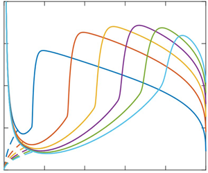
Although the jump position does not seem to be significantly influenced by the disk radius, the flow field and vortex structure appear to be more sensitive to the disk size (figures 2 and 3). These jump features are further examined by varying the flow rate over the same experimental range as that of Duchesne et al. (Reference Duchesne, Lebon and Limat2014) but for a disk almost twice and four times smaller. Figure 4 illustrates the influence of the flow rate on the film profile for a disk of radius  ${r_\infty } = 93.75$ (figure 4a),
 ${r_\infty } = 50$ (figure 4b) and
 ${r_\infty } = 25$ (figure 4c). Figure 4(a) typically illustrates the film profiles for a film draining at the edge of the disk at different flow rates. Although similar or equivalent flow details were not reported by Duchesne et al. (Reference Duchesne, Lebon and Limat2014), the profiles in figure 4(a) correspond to the same range of flow rates and conditions of their experiment. The figure shows that the boundary-layer thickness diminishes with increasing flow rate, following closely (2.12a), with the film thickness profile well reflected in (2.12b). The figure indicates that the jump radius and film heights at the leading and trailing edges of the jump grow with the Froude number. While the supercritical region extends in length and diminishes in thickness, the subcritical region shrinks in length with diminishing thickness growth with flow rate, evolving from an essentially linear to a logarithmic (lubrication) profile (excluding the vicinity of the edge). We shall refer to this figure when examining various characteristics of the jump.
Figure 4(c) shows that the monotonic growth of the film height in figure 4(a,b) is clearly replaced by a height that increases with the flow rate, reaching an overall maximum and decreasing as the flow rate is increased further. The results seem to suggest that a maximum for the maximum film height will show as well when  ${r_\infty } = 93.75$ and 50 if the flow rate increases further, but the flow may become unstable if the flow rate is further increased. This non-monotonicity in the jump height with increasing flow rate was also reported by Rao & Arakeri (Reference Rao and Arakeri2001) in their experimental study (see their figure 7). This maximum for the maximum film height shown in figure 4(c) is related to the competition between the accumulation at the jump and the drainage at the disk edge. When the flow rate is small, the jump occurs far upstream from the disk edge, and the flow at the jump is dominated by the viscous effect at the jump, leading to an increase in the jump height
 ${H_J}$ with increasing flow rate (Fr). In contrast, the drainage plays a significant role when the flow rate is large, and the jump occurs closer to the disk edge, resulting in a decrease in the jump height
 ${H_J}$ with increasing flow rate (Fr). Figure 4(c) also shows a significant change in the film profile in the subcritical region as well as smoothening in the jump region compared with figure 4(a,b). As the flow rate increases, the slope of the film profile in the subcritical region (especially the part near the jump) remains essentially unaffected for
 ${r_\infty } = 93.75$, remains unaffected in the small range of Fr and increases slightly in the large range of Fr for
 ${r_\infty } = 50$, and increases essentially for the whole range of Fr considered for
 ${r_\infty } = 25$. The steepness of the jump profile and the film profile in the subcritical region act as the adverse and favourable pressure gradients, respectively. We expect, and as we confirm below, a gradual and significant change in the flow field and vortex structure as the disk size increases.
Influence of the Froude number (flow rate) on the film profile for three different disk sizes: (a)  ${r_\infty } = 93.75$, (b)
 ${r_\infty } = 50$ and (c)
 ${r_\infty } = 25$. Here, Ga = 100 (50.11 < Re < 551.25), corresponding to the range of flow rate in the experiment of Duchesne et al. (Reference Duchesne, Lebon and Limat2014). Dash-dotted and dotted curves represent the locus of the film heights at the trailing and leading edges of the jump, respectively. Other dimensionless numbers are Bo = 1.19, and BoJ = 4.52–36.95 for r ∞ = 93.75, BoJ = 4.27–30.02 for r ∞ = 50 and BoJ = 3.84–15.28 for r ∞ = 25.

Further details of the influence of the disk size on the jump radius are reported in figure 5. The profiles are shown for three different disk sizes:  ${r_\infty } = 93.75$,
 ${r_\infty } = 50$ and
 ${r_\infty } = 25$. Figure 5(a) confirms the overall lack of sensitivity of the jump radius to the size of the disk, simultaneously indicating a decrease in the jump radius with increasing disk size. The figure also suggests, albeit in a faint manner, the tendency of the jump radius to grow linearly with the flow rate for the smaller disk size, in agreement with the measurements of Mohajer & Li (Reference Mohajer and Li2015), reported in their figure 4. In figure 5(b,c), we compare our theoretical predictions against the measurements of Duchesne (Reference Duchesne2014), available only for
 ${r_\infty } = 93.75$ and
 ${r_\infty } = 50$. For the cases
 ${r_\infty } = 93.75$ and 50, figure 5(b,c) shows that the theoretical predictions agree very well with the measured jump radius, tending to slightly overpredict the jump radius in the small-Fr range (Fr < 35), and slightly underpredict the radius for larger Fr (Fr > 35). We also added the radius distributions based on our scaling law (4.6) which we establish in § 4.1, showing a close agreement with both theory and experiment.
Influence of Fr (flow rate) for different disk sizes on the jump radius. (a) The prediction based on the present approach. Comparison between the present approach, the measurements of Duchesne (Reference Duchesne2014) and the present scaling (4.6) for (b) r ∞ = 93.75 and (c)  ${r_\infty } = 50$. Here Ga = 100, corresponding to the parameters in the experiment of Duchesne et al. (Reference Duchesne, Lebon and Limat2014).

Figure 6 illustrates the interplay between the flow rate and the disk size for various characterizing parameters of the jump. As indicated in figure 6(a), the film height  ${h_J}$ at the leading edge of the jump increases monotonically with increasing flow rate (Fr) for any disk size. This increase is the result of the viscous effect (Watson Reference Watson1964; Bowles & Smith Reference Bowles and Smith1992), which can be elucidated by applying (2.13a) at the jump and using the scaling of Bohr et al. (Reference Bohr, Dimon and Putzkaradze1993) for the jump radius. Thus, far from impingement, (2.13a) reduces to
 ${h_J}\sim (175/136)(r_J^2/Re) \propto F{r^{1/2}}/R{e^{1/4}}$, which reflects a monotonic increase with the flow rate, following
 $F{r^{1/4}}$ close to the trend observed in figure 6(a). This trend, however, varies slightly with the disk radius, which is not considered in the scaling of Bohr et al (Reference Bohr, Dimon and Putzkaradze1993).
Influence of Fr (flow rate) for different disk sizes on the film height at the leading edge of the jump (a), the film height at the trailing edge of the jump (maximum of the film height) (b), the difference between the film heights at the trailing and leading edges of the jump (c), the film height gradient at the jump (d), the jump length  ${L_J} \equiv {r_{J + }} - {r_{J - }}$ (e) and the vortex length
 ${L_{vortex}} \equiv {r_{v + }} - {r_{v - }}$ (f). Here Ga = 100, corresponding to the parameters in the experiment of Duchesne et al. (Reference Duchesne, Lebon and Limat2014). The dashed curves are predictions based on the lubrication approach (2.14a) and scaling of rJ (4.6).

Figure 6(b) shows that the height  ${H_J}$ at the trailing edge of the jump is smaller for a smaller disk (see also figure 3); for a smaller disk size, the jump occurs closer to the disk edge (figures 3 and 5a), as less flow is accumulated in the subcritical region due to a stronger drainage at the disk edge, leading to a smaller
 ${H_J}$. In contrast to
 ${h_J}$, figure 6(b) suggests that
 ${H_J}$ does not always increase monotonically with the flow rate. In fact,
 ${H_J}$ reaches a maximum for the disk of radius
 ${r_\infty } = 25$. As discussed earlier (see figure 4c), the non-monotonicity of
 ${H_J}$ is related to the interplay between the accumulation effect at the jump and the drainage effect at the disk edge. This behaviour, based on our numerical approach, can be confirmed by using the expression (2.14a) from lubrication theory and the scaling law for the jump radius (4.6) established shortly. The resulting approximate profiles for
 ${H_J}$ are shown in dashed curves in figure 6(b). It is worth noting that the non-monotonicity in the jump height is not captured if the scaling of Bohr et al. (Reference Bohr, Dimon and Putzkaradze1993) is used, which excludes the influence of the disk size on the jump radius. Furthermore, the height
 ${H_J}$ varies rather insignificantly with the flow rate for the smallest disk size, remaining essentially constant, again in agreement with the data in figure 4 of Mohajer & Li (Reference Mohajer and Li2015), as well as the earlier observation of Hansen et al. (Reference Hansen, Horluck, Zauner, Dimon, Ellegaard and Creagh1997). The non-monotonic behaviour of the jump height
 ${H_J}$ further results in the non-monotonicity in the difference between the heights at the trailing and leading edges of the jump,
 ${H_J} - {h_J}$ (figure 6c). As indicated in figure 6(d), the film height slope at the jump essentially decreases with the increase in the flow rate for all three different disk sizes, and a smoother jump profile is observed for a smaller disk size (also see figure 4). It is interesting to note that, in the small range of Fr, there is a small increase in the steepness of the jump for the largest disk size. This prediction is somewhat consistent with the observation of Chang et al. (Reference Chang, Demekhin and Takhistov2001), who observed that the jump becomes smoother when the flow rate is smaller than a critical value. However, they also reported that the wall vortex also disappeared in this case. The non-monotonicity is also reflected in the response of the jump length and vortex size in figures 6(e) and 6(f), respectively. In fact, Craik et al. (Reference Craik, Latham, Fawkes and Gribbon1981) found that the jump length increases monotonically with the flow rate (see their figure 5). A similar trend was also observed by Rao & Arakeri (Reference Rao and Arakeri2001) for a relatively large disk (see their figure 5), but they reported a decrease in the jump length with increasing flow rate for a small disk (see their figure 6). The monotonic increase in the vortex length was observed by Rao & Arakeri (Reference Rao and Arakeri2001), while the non-monotonic behaviour was illustrated by Craik et al. (Reference Craik, Latham, Fawkes and Gribbon1981). Both
 ${L_J}$ and
 ${L_{vortex}}$ are overall smaller for a smaller disk size.
To further explain the behaviour of the jump, we first refer to Avedisian & Zhao (Reference Avedisian and Zhao2000). By balancing the drag at the disk in the jump region with fluid inertia, and assuming a dominant viscous over gravity effect, Avedisian & Zhao (Reference Avedisian and Zhao2000) obtained a relation between the length of the jump and its radius as  ${L_J}{r_J}/{h_J} \approx Re$, where
 ${h_J}$ is the film thickness at the leading edge of the jump (see also the different treatment of Razis et al. (Reference Razis, Kanellopoulos and Van der Weele2021) for the planar jump). An approximate relation among the jump length, location and height can be derived by applying (2.11) at
 ${r_{J - }}$ and
 ${r_{J + }}$. We observe that both the slope and concavity are relatively small at these two locations (Bush & Aristoff Reference Bush and Aristoff2003), so (2.11) reduces to
 $136\,Re\,h \approx 525{r^2}$. By applying this relation at the leading and trailing edges of the jump and subtracting them, we arrive at
 ${L_J}({r_{J + }} + {r_{J - }})/({H_J} - {h_J}) \approx 136Re/525$. If we take
 ${r_J} \approx ({r_{J - }} + {r_{J + }})/2$, we obtain a more general relation than Avedisian & Zhao (Reference Avedisian and Zhao2000):
 \begin{equation}
L_J \approx \frac{68}{525}Re\frac{H_J -h_J}{r_J}.\end{equation}
This expression indicates that the behaviour of the jump length depends on the rate of increase of the height difference and the jump radius. Figures 5 and 6 show that while  ${r_J}$ increases monotonically with the flow rate (or Fr),
 ${H_J} - {h_J}$ experiences a decrease as the jump occurs closer to the edge of the disk (figure 6c). This decrease in
 ${H_J} - {h_J}$ as well as the shrinking jump length are also discernible in the profiles measured by Rao & Arakeri (Reference Rao and Arakeri2001) in their figure 7 for the smallest disk they considered.
Comparison of the free-surface profiles between our approach (black solid line) and the Navier–Stokes (NS) solution of Askarizadeh et al. (Reference Askarizadeh, Ahmadikia, Ehrenpreis, Kneer, Pishevar and Rohlfs2019, Reference Askarizadeh, Ahmadikia, Ehrenpreis, Kneer, Pishevar and Rohlfs2020), shown in red symbols in (a) and (b), respectively, for σ = 10 and 45 mN m−1, and corresponding obstacle heights of 1 and 0.05 mm. Flow fields based on (c) the present approach and (d) numerical simulation of Askarizadeh et al. (Reference Askarizadeh, Ahmadikia, Ehrenpreis, Kneer, Pishevar and Rohlfs2020), with the inset in (c) depicting the surface velocity and wall shear stress distributions. In all cases, Re = 381.97, Fr = 9.76 and r ∞ = 16.

The non-monotonicity in the vortex size as well as the disappearance of the vortex are related to the steepness of the jump profile and the slope of the film profile in the subcritical region. As shown in figure 6(d), the film gradient at the jump decreases monotonically, signifying the decrease in the steepness of the jump, and the recirculation zone disappears as the steepness of the jump is below a critical value. Before this critical value, flow separation happens, but the favourable pressure gradient in the subcritical region determines the location of the reattachment of the flow separation. In this case, the increase in the vortex size in the small range of Fr is caused by the essentially constant film profile gradient in the subcritical region, and the decrease in the vortex size in the middle range of Fr is attributed to the increase in the steepness of the film profile in the subcritical region (see figure 4c). The jump becomes of type 0 (no vortex) when Fr exceeds 39 for  ${r_\infty } = 25$. In addition, as indicated by Chang et al. (Reference Chang, Demekhin and Takhistov2001), the vortex under the jump disappears when the flow rate is smaller than a critical value; meanwhile, the jump length experiences a transition and becomes much wider (see their figure 9).
Finally, Chang et al. (Reference Chang, Demekhin and Takhistov2001) reported that, as the jump radius decreases significantly, the surface tension effect becomes important. They also noted that this feature corresponds to the type II jump observed by Ellegaard et al. (Reference Ellegaard, Hansen, Haaning, Hansen, Marcussen, Bohr, Hansen and Watanabe1998), who found that a surface roller appears under the free surface, and the jump becomes much smoother. The Navier–Stokes solution of Askarizadeh et al. (Reference Askarizadeh, Ahmadikia, Ehrenpreis, Kneer, Pishevar and Rohlfs2020) confirmed that as the surface roller appears, the vortex near the wall disappears. Clearly, this particular phenomenon is beyond the scope of our current study.
3.3. The influence of the obstacle height at the edge of the disk
Although we have extensively validated the present approach in Wang et al. (Reference Wang, Baayoun and Khayat2023) for a film freely draining at the disk edge, we further verify our model against the numerical solution of the Navier–Stokes equations when an obstacle is placed at the disk edge. As mentioned earlier, the solution strategy here is slightly different from the case of the flow of a freely draining film; we shoot for a known edge film thickness here instead of an infinity film slope at the edge of the disk. Askarizadeh et al. (Reference Askarizadeh, Ahmadikia, Ehrenpreis, Kneer, Pishevar and Rohlfs2019) explored the origin of the hydraulic jump. They identified two different flow regimes in the jump formation: gravity- and capillary-dominant flow regimes. Between these two regimes, there is the capillary–gravity regime, when both gravity and capillary effects play a role in the formation of the jump. They found that the gravity effect is important for a flow with high viscosity, density and flow rate, as well as low surface tension. Later, Askarizadeh et al. (Reference Askarizadeh, Ahmadikia, Ehrenpreis, Kneer, Pishevar and Rohlfs2020) investigated the heat transfer in the jump region. In figure 7, we compare our approach against their simulated flow for a fluid of density ρ = 1100 kg m−3 and kinematic viscosity ν = 10 cSt, at a flow rate Q = 30 ml s−1. The simulated jet is injected from a nozzle of radius a = 2.5 mm, impinging onto a horizontal circular disk of radius R ∞ = 40 mm. For the flow with surface tension σ = 10 mN m−1, the obstacle was 10 mm in length and 1 mm in height at the disk edge (figure 7a), and was 10 mm in length and 0.05 mm in height for σ = 45 mN m−1 (figure 7b), with corresponding simulation data taken from Askarizadeh et al. (Reference Askarizadeh, Ahmadikia, Ehrenpreis, Kneer, Pishevar and Rohlfs2019, Reference Askarizadeh, Ahmadikia, Ehrenpreis, Kneer, Pishevar and Rohlfs2020), respectively. The two figures indicate that the film thickness at the disk edge, resulting from the combined obstacle height, capillary length and the contribution of the weak power-law dependence on the flow rate, is sensibly the same.
The predicted profiles based on our approach are generally in good agreement with the numerical simulation for both cases. Recalling that the effect of surface tension is neglected in the present study, figure 7(a,b) suggests a minimal importance of surface tension, the discrepancy being localized at the jump level. For low surface tension (dominant gravity), our profile is slightly lower with a milder curvature than the exact numerical profile (figure 7a). Again, the ripple immediately downstream of the jump is commonly predicted in numerical simulations without surface tension, which is possibly due to the flow instability in the absence of surface tension; the flow instability is not present when the surface tension effect is included in the simulation (Fernandez-Feria et al. Reference Fernandez-Feria, Sanmiguel-Rojas and Benilov2019; Wang & Khayat Reference Wang and Khayat2021; Zhou & Prosperetti Reference Zhou and Prosperetti2022). At higher surface tension, the numerical curvature is milder, and our prediction for the film height at the jump is slightly higher than the result of the numerical simulation (figure 7b). The agreement between the current predictions and numerical simulations in the supercritical flow is very close, which is not surprising given the absence of strong film curvature, except for very near jet impingement. This discrepancy is due to our neglecting the impingement zone; our approach cannot capture accurately the jet profile. However, and as can be observed from figure 7(a,b), the disagreement has little consequence on the accuracy of our approach downstream of the impingement zone (see also figure 17c below). We have already explained the rationale behind neglecting the impingement zone in § 2.1.
Figure 7(c) depicts the predicted flow field as well as the wall shear stress and surface velocity distributions (inset), to be contrasted against the simulated flow field reproduced in figure 7(d) from the Navier–Stokes solution of Askarizadeh et al. (Reference Askarizadeh, Ahmadikia, Ehrenpreis, Kneer, Pishevar and Rohlfs2020). The vortex near the disk under the jump is clearly visible in figure 7(c), and is similar to the numerically predicted vortex in figure 7(d), of comparable height. It is slightly shorter because of the smoother jump profile as a result of the influence of the surface tension effect included in the numerical simulation of Askarizadeh et al. (Reference Askarizadeh, Ahmadikia, Ehrenpreis, Kneer, Pishevar and Rohlfs2020). We note that, in addition to the height of the obstacle, the length of the obstacle is also specified in the numerical simulation of Askarizadeh et al. (Reference Askarizadeh, Ahmadikia, Ehrenpreis, Kneer, Pishevar and Rohlfs2019, Reference Askarizadeh, Ahmadikia, Ehrenpreis, Kneer, Pishevar and Rohlfs2020), but this length is irrelevant in the current approach as we simply impose the film height near the disk edge. In this case, the current approach does not treat the flow over the obstacle, as well as the flow near the obstacle accurately. However, the length of the obstacle is an important parameter in the numerical simulation; beyond a critical obstacle length, the flow remains unaffected (Passandideh-Fard, Teymourtash & Khavari Reference Passandideh-Fard, Teymourtash and Khavari2011).
As indicated in the numerical simulation of Askarizadeh et al. (Reference Askarizadeh, Ahmadikia, Ehrenpreis, Kneer, Pishevar and Rohlfs2020), the height of the obstacle can affect significantly the flow structure; the jump transits from type 0 to type Ia, then to type Ib, and finally to type IIa and type IIb as the height is increased. As the effect of surface tension is not included in the present approach, we are unable to capture jumps of type Ib, type IIa and type IIb, but the current approach can still capture the type 0 and type Ia jumps, and partially explore the influence of the film thickness at the disk edge on the flow structure. As mentioned above, the film thickness at the disk edge when an obstacle is present is the combination of the obstacle height, capillary length and the contribution of the weak power-law dependence on the flow rate, which is a more complex issue than the situation when the flow drains freely at the disk edge (see § 4.2). To keep the treatment manageable in the presence of an obstacle, we simply impose the film thickness at the edge of the disk as the boundary condition.
We explore further the effect of the film thickness at the disk edge for Re = 381.97, Fr = 9.76 and r ∞ = 16. Similar to the experimental measurements of Bohr et al. (Reference Bohr, Ellegaard, Hansen and Haaning1996) and the Navier–Stokes solution of Askarizadeh et al. (Reference Askarizadeh, Ahmadikia, Ehrenpreis, Kneer, Pishevar and Rohlfs2020), figure 8 indicates that the flow in the supercritical region is unaffected by the value of the film thickness at the disk edge. In contrast, the flow in the subcritical and jump regions is significantly influenced when h ∞ varies. Figure 8(a) shows that the film thickness in the subcritical region increases overall with h ∞, pushing the jump location closer to the impinging jet, in agreement with Bohr et al. (Reference Bohr, Ellegaard, Hansen and Haaning1996), Passandideh-Fard et al. (Reference Passandideh-Fard, Teymourtash and Khavari2011) and Askarizadeh et al. (Reference Askarizadeh, Ahmadikia, Ehrenpreis, Kneer, Pishevar and Rohlfs2019, Reference Askarizadeh, Ahmadikia, Ehrenpreis, Kneer, Pishevar and Rohlfs2020). However, as we show in the inset of figure 8(a), both the jump radius and maximum film height saturate to a constant value in the lower range of h ∞, which is the case when the flow drains freely at the disk edge. It also suggests that the flow at the jump is not sensitive to the edge condition for the free-draining situation, as long as the film thickness at the disk edge is close to a draining fluid thickness with no obstacle. Meanwhile, the wall shear stress in the subcritical region is greatly affected; the wall shear stress decreases overall as flow is slowed down when the film thickness in the subcritical region is increased (figure 8b), and the strength of the separation zone increases with the increase of h ∞ as a result of the steepening of the jump (figure 8b–e). In fact, Askarizadeh et al. (Reference Askarizadeh, Ahmadikia, Ehrenpreis, Kneer, Pishevar and Rohlfs2020) also showed that the heat transfer characteristics also exhibit similar features to the wall shear stress. Although we have shown that the vortex size increases with the rise of h ∞, the behaviour of the vortex size is much more complex in reality. The surface tension becomes important when the jump radius becomes smaller, and instability will also appear as the film height rises. In this case, the size of the vortex near the wall will decrease until it disappears (Craik et al. Reference Craik, Latham, Fawkes and Gribbon1981; Bohr et al. Reference Bohr, Ellegaard, Hansen and Haaning1996; Chang et al. Reference Chang, Demekhin and Takhistov2001; Askarizadeh et al. Reference Askarizadeh, Ahmadikia, Ehrenpreis, Kneer, Pishevar and Rohlfs2020), and hydraulic jump either becomes unstable (Craik et al. Reference Craik, Latham, Fawkes and Gribbon1981) or transfers to a type Ib jump (only a surface roller shows) then type II jump (Bohr et al. Reference Bohr, Ellegaard, Hansen and Haaning1996; Askarizadeh et al. Reference Askarizadeh, Ahmadikia, Ehrenpreis, Kneer, Pishevar and Rohlfs2020), with both a wall vortex and a surface roller. As the current study focuses on the type I jump or type Ia jump (Askarizadeh et al. Reference Askarizadeh, Ahmadikia, Ehrenpreis, Kneer, Pishevar and Rohlfs2020), the surface tension effect is not considered.
Influence of the film thickness at the disk edge on (a) the free-surface profile (solid curves) and the boundary-layer thickness (dashed curves) and (b) the wall shear stress. Shown in (c–e) are the streamlines for (c) h ∞ = 0.65, (d) h ∞ = 0.85 and (e) h ∞ = 1.05. The inset in (a) shows the dependence of the jump radius and maximum film height on the film thickness at the disk edge. Here, Re = 381.97, Fr = 9.76 and r ∞ = 16 are parameters corresponding to the simulation of Askarizadeh et al. (Reference Askarizadeh, Ahmadikia, Ehrenpreis, Kneer, Pishevar and Rohlfs2019, Reference Askarizadeh, Ahmadikia, Ehrenpreis, Kneer, Pishevar and Rohlfs2020).

4. Scaling analysis and estimates
Duchesne et al. (Reference Duchesne, Lebon and Limat2014) proposed a scaling law for the jump radius based on the constancy of the local Froude number at the trailing edge of the jump. This scaling law includes the influence of the disk size on the jump radius. Later, they proposed a modified scaling law in Duchesne & Limat (Reference Duchesne and Limat2022), which also includes the influence of the disk size. In the current study, we revisit the scaling law for the jump radius by including the effect of the film thickness at the edge, and establish scaling laws for the other jump properties, such as the jump length, vortex size, energy loss across the jump and conjugate depth ratio, among others. The validation of the scaling laws and estimates is conducted against existing measurements and numerical simulations for a flow draining freely at the disk edge, as well as against our numerical approach (Wang et al. Reference Wang, Baayoun and Khayat2023).
4.1. The scaling law for the jump radius
By considering the horizontal momentum conservation across the jump, and assuming lubrication flow downstream of the jump, Higuera (Reference Higuera1994) derived an expression for the jump location in the plane. Following his treatment, we first consider the weak form of the radial momentum equation (2.6), which takes the following approximate form across a narrow jump:
 \begin{equation}Re\left[ {\int_0^{{h_J}} {{u^2}({r_{J - }},z)\,\textrm{d}z} - \int_0^{{H_J}} {{u^2}({r_{J + }},z)\,\textrm{d}z} } \right] = \frac{{Re}}{{2F{r^2}}}(H_J^2 - h_J^2) + {L_J}{\tau _w}(r = {r_J}),\end{equation}
where  ${L_J}$ is the jump length and
 ${\tau _w}(r = {r_J}) = {u_z}(r = {r_J},z = 0)$ is the wall shear stress at the jump. Here,
 ${r_{J - }}$ and
 ${r_{J + }}$ are radial locations immediately upstream and downstream of the jump, with corresponding heights
 ${h_J} \equiv h(r = {r_{J - }})$ and
 ${H_J} \equiv h(r = {r_{J + }})$, respectively. Assuming the jump length to be relatively small
 $({L_J} \ll {r_J})$, the gravity term to be negligible compared with the momentum flux in the supercritical region and the momentum flux term to be negligible compared with the gravity term in the subcritical region, (4.1) reduces to
 \begin{equation}\int_0^{{h_J}} {{u^2}({r_{J - }},z)\,\textrm{d}z} \approx \frac{{H_J^2}}{{2F{r^2}}}.\end{equation}
It is helpful to establish a scaling law independent of the choice of the velocity profile. When gravity is negligible, the supercritical velocity profile (2.8) reduces to  $u({r_{J - }},z) = {u_J}f(\eta )$, where
 $f(\eta )$ is a non-specified similarity function of
 $\eta = z/{h_J}$, and is given by (2.4) for a cubic profile. In this case, we deduce from (2.6a) that
 ${u_J} \equiv U({r_{J - }}) = 1/2{\chi _1}{r_J}{h_J}$, and recalling (4.2), we obtain
 \begin{equation}{H_J} \approx \sqrt {\frac{{{\chi _2}}}{{2\chi _1^2}}} \frac{{Fr}}{{{r_J}\sqrt {{h_J}} }},\end{equation}
where  ${\chi _1} = \int_0^1 {f(\eta )\,\textrm{d}\eta }$ and
 ${\chi _2} = \int_0^1 {{f^2}(\eta )\,\textrm{d}\eta }$. For a cubic profile
 ${\chi _1} = 5/8$ and
 ${\chi _2} = 17/35$. These values are close to those based on Watson's (Reference Watson1964) similarity profile:
 ${\chi _1} = 0.615$ and
 ${\chi _2} = 0.476$. The flow downstream of the jump must be analysed in order to determine the still unknown jump radius rJ. The earlier estimates imply that the convective terms in (2.1b) are negligible in this region, and then the balance of viscous and pressure forces for lubrication flow leads to the following downstream jump height from (2.14a):
 ${H_J} = {[h_\infty ^4 + 6(F{r^2}/Re)\,\textrm{ln}({r_\infty }/{r_J})]^{1/4}}$. Next, the general supercritical thickness, which reduces to (2.13a) for a cubic profile, yields the film thickness at the jump leading edge:
 ${h_J} = (2/3)({\chi _0}{\chi _1}/{\chi _2})(r_J^2/Re) + (1/2{\chi _1} - ({\chi _1} - {\chi _2})/4{\chi _1}{\chi _2})(1/{r_J})$, where
 ${\chi _0} = f^{\prime}(\eta = 0)$, which is equal to 3/2 for a cubic profile. Finally, substituting for
 ${h_J}$ and
 ${H_J}$ in (4.3), we obtain the desired equation for the jump radius, including the effect of the disk radius and the film thickness at the edge of the disk:
 \begin{equation}\frac{{\chi _2^2F{r^4}}}{{4\chi _1^4{r_J}^4}}{\left[ {\frac{2}{3}\frac{{{\chi_0}{\chi_1}}}{{{\chi_2}}}\frac{{{r_J}^2}}{{Re}} + \frac{1}{{{r_J}}}\left( {\frac{1}{{2{\chi_1}}} - \frac{{{\chi_1} - {\chi_2}}}{{4{\chi_1}{\chi_2}}}} \right)} \right]^{ - 2}} \approx 6\frac{{F{r^2}}}{{Re}}\ln \left( {\frac{{{r_\infty }}}{{{r_J}}}} \right) + {h_\infty }.\end{equation}
Under some conditions, this relation can be simplified. For a film draining freely at the disk edge, the jump is either of type 0 or type Ia. As indicated by Bowles & Smith (Reference Bowles and Smith1992), the effect of viscosity in the incident profile upstream of the jump is responsible for the substantial increase in thickness of the incident layer ahead of the jump. Watson's (Reference Watson1964) solution as well as the film height profile (2.13a) account for the viscous effect in the upstream profile. This profile suggests that the radial spreading near impingement dominates the descending portion of the film, and the viscous effect dominates the ascending portion of the film (see figure 3). In this case, the jump tends to occur downstream of the ascending portion of the film thickness. On the other hand, when an obstacle is placed at the disk edge, the situation is different. As indicated in figure 3 of Bohr et al. (Reference Bohr, Ellegaard, Hansen and Haaning1996), when the height of the obstacle increases, the jump radius decreases and the film height downstream of the jump increases, but the flow in the supercritical region does not change. As the jump radius decreases, the jump still occurs downstream of the ascending portion of the film for a relatively small obstacle height and the jump remains of type Ia, but the jump occurs in the descending portion of the film for a relatively large obstacle height and the jump transits to type II. Hence, assuming a relatively large jump radius, the film thickness at the leading edge of the jump reduces to  ${h_J} \approx (2/3)({\chi _0}{\chi _1}/{\chi _2})(r_J^2/Re)$. For a draining film at the disk edge, we show shortly that the film thickness at the edge is estimated as
 ${h_\infty } \approx {(27/70)^{1/3}}{(Fr/{r_\infty })^{2/3}}$ from (4.8) in the absence of the surface tension effect. Consequently, (4.4) reduces to a somewhat more familiar and tractable form:
 \begin{equation}{r_J}{\bigg[ {\frac{1}{6}{{\left( {\frac{{27}}{{70}}} \right)}^{4/3}}{{\left( {\frac{{Fr}}{{{r_\infty }}}} \right)}^{8/3}} + \frac{{F{r^2}}}{{Re}}\,\textrm{ln}\left( {\frac{{{r_\infty }}}{{{r_J}}}} \right)} \bigg]^{1/8}} \approx \gamma F{r^{1/32}}R{e^{1/4}},\end{equation}
where  $\gamma = {((3/32)(\chi _2^4/\chi _1^6\chi _0^2))^{1/8}}$ is a constant, which depends only on the type of velocity profile adopted in the averaging process. For a cubic profile, γ = 2/3. This scaling law (4.5) can be simplified further for a disk of relatively large diameter, so the first term on the left-hand side becomes negligible (
 ${h_\infty } \to 0$), yielding
 \begin{equation}{r_J}{\left[ {\textrm{ln}\left( {\frac{{{r_\infty }}}{{{r_J}}}} \right)} \right]^{1/8}} = \gamma F{r^{1/4}}R{e^{3/8}}.\end{equation}
This scaling law is similar to the one obtained by Duchesne & Limat (Reference Duchesne and Limat2022), who adopted the similarity velocity and height profiles for the flow in the viscous region from Watson (Reference Watson1964), yielding γ = 0.5 (compared with γ = 0.67 when a cubic profile is used). If the logarithmic dependence is dropped, we recover the scaling law of Bohr et al. (Reference Bohr, Dimon and Putzkaradze1993), who suggested the value γ = 0.73.
Relation (4.6) is very similar to the scaling law of Duchesne et al. (Reference Duchesne, Lebon and Limat2014), which we recast here as  ${r_J}{[\textrm{ln}({r_\infty }/{r_J})]^{3/8}} = \gamma F{r^{1/4}}R{e^{3/8}}$, where
 $\gamma = (1/2{\rm \pi} ){({\rm \pi} /6)^{3/8}}Fr_J^{ - 1}$. We observe that Duchesne et al. (Reference Duchesne, Lebon and Limat2014) established their scaling law by assuming that
 $F{r_J} \equiv Fr/2{r_J}H_J^{3/2}$ is constant, therefore allowing them to eliminate
 ${H_J}$ between this relation and the lubrication result (2.14a)
 ${H_J} = {[6(F{r^2}/Re)\,\textrm{ln}({r_\infty }/{r_J})]^{1/4}}$ to obtain the expression for
 ${r_J}$. Their scaling law is therefore semi-empirical since the value of
 $F{r_J}$ must be imposed from experiment. In contrast, relation (4.5) and its simplified form (4.6), as well as that of Higuera (Reference Higuera1994) for a planar jump, do not rely on empirical input. Finally, although the relations (4.5) and (4.6) are derived for a general similarity velocity profile, they are used based on the cubic profile to generate numerical results.
Figure 9 shows the comparison between our scaling law (4.6) and other laws, including the measurements of Hansen et al. (Reference Hansen, Horluck, Zauner, Dimon, Ellegaard and Creagh1997). Our scaling law (4.6) is as accurate as that of Rojas, Argentina & Tirapegui (Reference Rojas, Argentina and Tirapegui2013). This latter relates the radius of the jump, in particular, to the height downstream of the jump (see their relation (15)). In the absence of surface tension, the relation, written here as  ${r_J} \approx {[(9/70)(ReF{r^2}/H_J^2)]^{1/4}}$, is based on their spectral approach for inertial–lubrication flow (Rojas et al. Reference Rojas, Argentina, Cerda and Tirapegui2010) and the inviscid Belanger equation (White Reference White2006).
Comparison of scaling laws for the influence of the Froude number (flow rate) on the jump radius. Our scaling law (4.6) is compared against the scaling law of Rojas et al. (Reference Rojas, Argentina and Tirapegui2013). Measurements of Hansen et al. (Reference Hansen, Horluck, Zauner, Dimon, Ellegaard and Creagh1997) are added for reference. Results for water (ν = 1 cSt) (Ga = 627 840) are in red, those for silicone oil (ν = 15 cSt) (Ga = 2790) are in blue and those for silicone oil (ν = 95 cSt) (Ga = 70) are in green.

We recall that Rojas et al. (Reference Rojas, Argentina and Tirapegui2013) fixed their downstream thickness from the experiment in both their numerical solution and scaling. It is important to observe that our scaling law is not expected to remain accurate for low-viscosity fluids because it is based on the lubrication assumption. However, it seems to yield a reasonably accurate description if γ is slightly readjusted from 2/3. We have taken γ = 0.45 in figure 9 for water. Finally, the discrepancy at low flow rates is not surprising since it was difficult to observe the jump, so the first few data points are not reliable (Hansen et al. Reference Hansen, Horluck, Zauner, Dimon, Ellegaard and Creagh1997). Another source for the discrepancy at low flow rates for (4.6) and existing scaling laws is the narrow or shock-like assumption of the hydraulic jump made and only the ascending part of  ${h_J}$ is kept when deriving the scaling.
Finally, we show how our scaling law (4.6) can be used to estimate the (constant) value of  $F{r_J}$. We consider the flow on a large disk so
 ${r_\infty } \gg {r_J}$. In this case, assuming lubrication subcritical flow, evaluating (2.14a) at the jump and keeping the dominant terms, we have
 ${H_J} \approx {(6(F{r^2}/Re)\,\textrm{ln}\,{r_\infty })^{1/4}}$. Simultaneously, (4.6) reduces to
 ${r_J} \approx \gamma F{r^{1/4}}R{e^{3/8}}{(\textrm{ln}\,{r_\infty })^{ - 1/8}}$. Then, recalling the definition
 $F{r_J} = Fr/2{r_J}H_J^{3/2}$, we have
 \begin{equation}F{r_J} = \frac{1}{{2 \times {6^{3/8}}\gamma {{(\textrm{ln}\,{r_\infty })}^{1/4}}}},\end{equation}
which clearly demonstrates that  $F{r_J}$ is independent of Fr (or Re), and depends only on the size of the disk. In addition, as reflected in the scaling of the jump radius (4.6), the value of γ depends only on the velocity profile adopted, confirming the constancy of
 $F{r_J}$. The independence of
 $F{r_J}$ of the flow rate and viscosity is consistent with the measurements of Duchesne et al. (Reference Duchesne, Lebon and Limat2014), who also found that
 $F{r_J}$ is independent of surface tension. This behaviour is also consistent with the experimental findings of Mohajer & Li (Reference Mohajer and Li2015), who found that
 $F{r_J}$ is independent of the flow rate, but is dependent on surface tension. They attributed this dependence on surface tension to the edge condition, as the flow only drains out of the disk at one outlet, instead of the uniform edge flow around the disk in Duchesne et al. (Reference Duchesne, Lebon and Limat2014). Moreover, they also found that
 $F{r_J}$ decreases weakly with increasing disk size. This weak dependence on the disk size is consistent with the behaviour shown in (4.7). In contrast, for a planar hydraulic jump, Dhar et al. (Reference Dhar, Das and Das2020) found that
 $F{r_J}$ changes slightly with the Reynolds number, the channel length as well as the channel inclination. Although the origin of the constancy of
 $F{r_J}$ is to date not fully understood, Dhar et al. (Reference Dhar, Das and Das2020) attributed the difference between the cases of the circular and the planar hydraulic jump to the definition of
 $F{r_J}$; for a circular hydraulic jump,
 $F{r_J}$ involves both the jump radius and jump height, but it involves only the jump height for a planar hydraulic jump. In this case, based on the definition of
 $F{r_J} = Fr/2{r_J}H_J^{{3 / 2}}$ for a circular hydraulic jump, a constant
 $F{r_J}$ (independent of the flow rate) indicates that the denominator scales like Fr:
 ${r_J}H_J^{{3 / 2}} \sim Fr$. If γ is taken equal to 0.54 (instead of 0.67 for a cubic profile), then (4.7) yields
 $F{r_J} = 0.32$, in agreement with the data from the measurements of Duchesne et al. (Reference Duchesne, Lebon and Limat2014) for
 ${r_\infty } = 93.75$, based on the jump height estimated from lubrication flow. It is important to recall that we arrived at (4.7) by assuming that the jump radius is small relative to the disk radius (
 ${r_\infty } \gg {r_J}$). As we see later, the constancy of
 $F{r_J}$ may not hold under some flow conditions.
4.2. The film thickness and velocity at the edge of the disk for a freely draining film
The thickness at the edge of the disk remains largely unaddressed in the literature, as the flow near the disk edge experiences a complex interplay of inertia, gravity and surface tension (Higuera Reference Higuera1994; Wang et al. Reference Wang, Baayoun and Khayat2023). For a film draining freely off the disk edge, there are mainly two approaches to determine the film height or equivalent conditions at the disk: imposing an infinite slope (Bohr et al. Reference Bohr, Dimon and Putzkaradze1993; Kasimov Reference Kasimov2008; Dhar et al. Reference Dhar, Das and Das2020; Wang et al. Reference Wang, Baayoun and Khayat2023) or assuming the edge thickness to be essentially equal to the capillary length (Duchesne et al. Reference Duchesne, Lebon and Limat2014; Ipatova et al. Reference Ipatova, Smirnov and Mogilevskiy2021; Duchesne & Limat Reference Duchesne and Limat2022). In the experimental work of Duchesne et al. (Reference Duchesne, Lebon and Limat2014), they found that there are mainly two different scenarios for the flow at the disk edge: total wetting and partial wetting. For the total wetting, the flow leaves the top surface of the disk and wets the lateral edge fully. In this case, Duchesne et al. (Reference Duchesne, Lebon and Limat2014) found that the edge film thickness is predominantly equal to the capillary length for silicone oil, but also follows a weak power-law dependence on the flow rate. In contrast, when using a water–glycerol mixture as the working fluid, they found that the film flows under partial wetting conditions. Even for a clean enough glass disk, all the top surface of the disk remains wetted, but dewetting occurs on the lateral edge of the disk, with the formation of rivulets, causing a slight break in the axisymmetry of the flow. Nevertheless, the film thickness remains nearly constant with relative fluctuations due to the vicinity of the rivulets. The constant film thickness is very close to the capillary length  $\sqrt {\sigma /\rho g} $ of the fluid, which results from the balance between the hydrostatic pressure and the surface tension forces at the disk perimeter. This value is also consistent with the measurements of Dressaire et al. (Reference Dressaire, Courbin, Crest and Stone2010).
When related to the capillary length, the film thickness at the disk edge is essentially equal to the thickness of the liquid film under static conditions. This is not an unreasonable analogy since the flow downstream of the jump has predominantly the character of gradually varied and slow flow. This static thickness is governed by the minimum free energy, and was given by Lubarda & Talke (Reference Lubarda and Talke2011), which is recast here as  ${h_s} = (2/\sqrt {Bo} )\,\textrm{sin}({\theta _Y}/2)$, where
 ${\theta _Y}$ is the contact angle. This expression is equivalent to expression (5.1) of Duchesne & Limat (Reference Duchesne and Limat2022); see also de Gennes, Brochard-Wyart & Quéré (Reference de Gennes, Brochard-Wyart and Quéré2004) for further interpretation.
In addition to this static character, Duchesne et al. (Reference Duchesne, Lebon and Limat2014) found that the edge film thickness follows a weak power-law dependence on the flow rate. The film thickness at the edge may then be construed as comprising static and dynamic contributions.
To explore the dynamic component of the film height at the disk edge, we follow Yang & Chen (Reference Yang and Chen1992) and Yang, Chen & Hsu (Reference Yang, Chen and Hsu1997), and apply the minimum mechanical (Gibbs free) energy principle. We thus consider the minimum of the energy flux, and set  $(\partial /\partial h)\int_0^h {((1/2)F{r^2}{u^2} + h)ur\,\textrm{d}z} = 0$ at
 $r = {r_\infty }$. This principle states that a fluid flowing over the edge of a disk under the influence of a hydrostatic pressure gradient will adjust itself so that the mechanical energy within the fluid will be minimum with respect to the film thickness at the disk edge. Since the flow is predominantly slow and of lubrication character in the subcritical region (Duchesne et al. Reference Duchesne, Lebon and Limat2014), we then can use
 $u = (3/2r{h^3})(hz - {z^2}/2)$ (Wang & Khayat Reference Wang and Khayat2019), yielding the following estimates for the edge thickness (and average velocity
 $\langle {u_\infty }\rangle = 1/2{r_\infty }{h_\infty }$):
 \begin{equation}{h_d} \approx {\left( {\frac{{27}}{{70}}} \right)^{1/3}}{\left( {\frac{{Fr}}{{{r_\infty }}}} \right)^{2/3}}.\end{equation}
Although expression (4.8) seems to yield overall a good agreement with numerical and experimental results, it is not expected to hold when the subcritical flow deviates from lubrication flow, especially near the disk edge where inertial (and possibly surface tension) effects become tangible. Our own numerical predictions suggest that the flow can accelerate considerably near the edge for the local Froude number  $F{r_l}$ to exceed unity near the edge (see figure 11 in Wang et al. Reference Wang, Baayoun and Khayat2023). We recall the local Froude number in terms of the average velocity and film height as
 $F{r_l} = Fr\langle u\rangle /\sqrt h$. Noting from (2.6a) that
 $\langle u\rangle = 1/2rh$, then
 $F{r_l} = Fr/2r{h^{3/2}}$. Upon setting
 $F{r_l} = 1$ at the edge of the disk, we obtain
 \begin{equation}{h_d} = {\left( {\frac{1}{4}} \right)^{1/3}}{\left( {\frac{{Fr}}{{{r_\infty }}}} \right)^{2/3}}.\end{equation}
In fact, considering the effect of surface tension at the disk edge, Rahman, Faghri & Hankey (Reference Rahman, Faghri and Hankey1992) proposed an expression for the film thickness at the edge, which is the sum of the height obtained based on the exit Froude number being equal to 1 and σ/ρgR, in which R is the radius of curvature at the exit. In this case, the methodology in Rahman et al. (Reference Rahman, Faghri and Hankey1992) is consistent with (4.9) if the surface tension effect is not considered. More recently, Wang & Khayat (Reference Wang and Khayat2019) assumed that the edge film thickness is given by  ${h_\infty } = {h_s} + {h_d}$, comprising the effects of surface tension, inertia and gravity. In this work, only the effects of inertia and gravity are considered so
 ${h_\infty } = {h_d}$.
Aside from a difference of a few per cent in the coefficients, expression (4.8) or (4.9) yields the same dependence of the edge thickness on the flow parameters, involving only the Froude number and disk radius. The validity of the two estimates is established by comparison against our numerical result. Figure 10 shows that the numerical predictions for the edge thickness (figure 10a,b) and average velocity (figure 10c) follow closely (4.8) for low flow rates and (4.9) for high flow rates. The numerical (solid) curves in figure 10 fall between the two estimates over the entire Fr range considered. It eventually merges with the (4.9) curve as Fr increases beyond the range shown. Recalling that we determine the edge condition by assuming an infinite slope at the disk edge, the obtained film thickness at the disk edge indeed depends on the flow conditions, which we explore further below. In other words, the flow upstream is sensitively influenced by edge conditions (Higuera Reference Higuera1994).
Influence of Fr (flow rate) on film thickness h ∞ and the average velocity  $Fr\langle {u_\infty }\rangle$ at the edge of the disk. (a,c) Predictions based on the present approach against expressions (4.8) and (4.9). (b) Comparison between the present approach and the measurements in Duchesne (Reference Duchesne2014). Here, Ga = 100 (50.11 < Re < 551.25) and r ∞ = 93.75, corresponding to the range of flow rates in the experiment of Duchesne et al. (Reference Duchesne, Lebon and Limat2014).

The measurements of the film thickness at the disk edge were carried out for silicone oil by Duchesne (Reference Duchesne2014), who found that the film thickness is only weakly dependent on the flow rate. In order to assess this dependence, we compare our theoretical estimate (4.8) for the dynamic contribution against experiment after subtracting the static contribution from the measurements of Duchesne (Reference Duchesne2014). For this, we first note the surface tension σ = 20 mN m−1, and, for a best fit, we choose the static contact angle  ${\theta _Y} = {\rm \pi}/4$. The close agreement in figure 10(b) between our numerical profile and the measurements of Duchesne (Reference Duchesne2014) highlights the existence and contribution of the dynamic component of the thickness at the edge of the disk.
Figure 11 displays the influence of the disk radius on the film thickness at the edge for two different flow rates corresponding to Re = 854, Fr = 97 (in red) and Re = 356, Fr = 194 (in blue), for  $50 < {r_\infty } < 80$. The solid curves correspond to our numerical predictions and the dashed curves are based on expression (4.9), showing a close agreement. This also indicates that the local Froude number has reached unity near the edge as a result of flow acceleration. The edge thickness decreases essentially at the same rate with respect to the disk radius independently of the flow rate. The decrease of
 ${h_\infty }$ in the figure appears to be almost linear in both cases but it follows the
 $r_\infty ^{ - 2/3}$ behaviour shown in (4.9). We have also added four values of the edge thickness based on the Navier–Stokes solution of Fernandez-Feria et al. (Reference Fernandez-Feria, Sanmiguel-Rojas and Benilov2019) when the effect of surface tension is not considered, which agree with our predictions and expression (4.9) to within a few per cent; the two red circles correspond to the Navier–Stokes profiles in figure 2(a,b).
Influence of r ∞ (disk radius) on thickness h ∞ at the edge of the disk. Here, red curves and circle symbols correspond to Re = 854, Fr = 97, and blue curves and circle symbols correspond to Re = 356, Fr = 194. Simulation results come from the Navier–Stokes solutions of Fernandez-Feria et al. (Reference Fernandez-Feria, Sanmiguel-Rojas and Benilov2019).

4.3. The jump length and vortex size
We identify the jump length,  ${L_J} \equiv {r_{J + }} - {r_{J - }}$, as the difference in position between the leading edge of the jump and its trailing edge (location of maximum film height). Figure 12 illustrates the dependence of the jump length, vortex length and height on the film thickness at the disk edge for the same parameter range used in figure 7. All three quantities increase when the subcritical film thickens. In particular, both the jump and vortex lengths grow at the same rate, while the vortex height grows more rapidly with the film thickness. We already reported in figure 6 that the jump and vortex lengths experience the same growth rate with the flow rate, especially in the lower-Fr range. Whether the correlation between the jump length and vortex size exists under more general conditions is an interesting and fundamental issue, which we explore further next.
Dependence of the jump length, vortex length and vortex height on the film thickness at the disk edge. Here, Re = 381.97, Fr = 9.76 and r ∞ = 16 are parameters corresponding to the simulation of Askarizadeh et al. (Reference Askarizadeh, Ahmadikia, Ehrenpreis, Kneer, Pishevar and Rohlfs2019, Reference Askarizadeh, Ahmadikia, Ehrenpreis, Kneer, Pishevar and Rohlfs2020).

By balancing the drag at the disk in the jump region with fluid inertia, and assuming dominant viscous over gravity effects, Avedisian & Zhao (Reference Avedisian and Zhao2000) obtained a relation between the length of the jump and its radius as  ${L_J}{r_J}/{h_J} \approx Re$, where
 ${h_J}$ is the film thickness at the leading edge of the jump (see also the different treatment of Razis et al. (Reference Razis, Kanellopoulos and Van der Weele2021) for the planar jump). An approximate relation among the jump length, location and height can be derived by applying (2.11) at
 ${r_{J - }}$ and
 ${r_{J + }}$. We observe that both the slope and concavity are relatively small at these two locations (Bush & Aristoff Reference Bush and Aristoff2003), so (2.11) reduces to
 $136\,Re\,h \approx 525{r^2}$. By applying this relation at the leading and trailing edges of the jump and subtracting them, we arrive at
 ${L_J}({r_{J + }} + {r_{J - }})/({H_J} - {h_J}) \approx 136Re/525$. If we take
 ${r_J} \approx ({r_{J - }} + {r_{J + }})/2$, we obtain a more general relation than Avedisian & Zhao (Reference Avedisian and Zhao2000):
 \begin{equation}{L_J} \approx \frac{{68}}{{525}}Re\frac{{{H_J} - {h_J}}}{{{r_J}}}.\end{equation}
We can further simplify this expression to obtain a relation between the jump length and jump radius. We first note that at the leading edge of the jump,  $r = {r_{J - }}$, where the film slope is small, (2.7b) yields
 ${h_J} \approx {(272F{r^2}/875r_J^2)^{1/3}}$. The trailing edge,
 $r = {r_{J + }}$, is part of the subcritical region where the local Froude number is sensibly constant (Duchesne et al. Reference Duchesne, Lebon and Limat2014; Wang & Khayat Reference Wang and Khayat2019; Wang et al. Reference Wang, Baayoun and Khayat2023), except perhaps near the edge where the flow may accelerate. Recalling the definition of the local Froud number at the jump location, we have
 ${H_J} = {(Fr/2{r_J}F{r_J})^{2/3}}$. In this case
 \begin{equation}{L_J} \approx CRe{\left( {\frac{{F{r^2}}}{{{r_J}^5}}} \right)^{1/3}},\end{equation}
where  $C = (68/525)[{(1/2F{r_J})^{2/3}} - {(272/875)^{1/3}}]$ is a constant that depends on
 $F{r_J}$, which is independent of Fr (or Re), and depends only on the size of the disk (see expression (4.7)). Interestingly, if the scaling law of Bohr et al. (Reference Bohr, Dimon and Putzkaradze1993) is used:
 ${r_J} \approx 0.73R{e^{3/8}}F{r^{1/4}}$, then we find from (4.11) that
 ${L_J} \approx 0.73CR{e^{3/8}}F{r^{1/4}}$. In other words, the jump length also scales like the jump radius. Perhaps a more accurate estimate would be to adopt the scaling law (4.6) or that of Duchesne et al. (Reference Duchesne, Lebon and Limat2014), which accounts for the influence of the disk radius. Thus, by applying the scaling law (4.6) to determine the jump radius, we use (4.11) to obtain an estimate of the jump length in terms of the flow parameters Re, Fr and
 ${r_\infty }$. We suspect that the vortex length may follow closely (4.11) if a constant different from C is used. Although it is difficult to establish this correlation, it is worth assessing its validity numerically (see next).
Figure 13 shows the influence of the flow rate on the jump and vortex lengths, based on the profiles corresponding to the flow rate range of Duchesne et al. (Reference Duchesne, Lebon and Limat2014) in figure 4(a). The behaviour of the jump length LJ with respect to the flow rate agrees qualitatively with the measurements of Craik et al. (Reference Craik, Latham, Fawkes and Gribbon1981) (see their figure 6) and Rao & Arakeri (Reference Rao and Arakeri2001) (see their figure 6). In addition, as indicated in figure 17 below, the jump length (the radial distance between the two vertical dotted lines) obtained from the present approach also agrees qualitatively with the jump length of the measurements of Duchesne et al. (Reference Duchesne, Lebon and Limat2014). Figure 13 shows that the dependence of the jump length on the flow rate follows closely  ${L_J}\sim F{r^{1/2}}$. This behaviour becomes closely mimicked by estimate (4.11) once the dependence of
 ${r_J}$ on the flow rate is established. This can be done by adopting the scaling law (4.6). Alternatively, for the range of flow rates considered in figure 13, which is the same as the range examined by Duchesne et al. (Reference Duchesne, Lebon and Limat2014), the data in figure 5(a,b) suggest that the jump radius follows closely
 ${r_J} \approx 1.08F{r^{7/10}}$, yielding the
 ${L_J}\sim F{r^{1/2}}$ behaviour in figure 14. Incidentally, the
 ${r_J}\sim F{r^{7/10}}$ behaviour is also consistent with the measurements of Hansen et al. (Reference Hansen, Horluck, Zauner, Dimon, Ellegaard and Creagh1997).
Influence of the Froude number (flow rate) on the jump and vortex lengths. Solid and dash-dotted curves based on our predictions and the dashed curve based on expression (4.11). Here FrJ = 0.32, Ga = 100 and r ∞ = 93.75, corresponding to the parameters in the experiment of Duchesne et al. (Reference Duchesne, Lebon and Limat2014).

Influence of Fr (flow rate) on (a) the film depth immediately upstream and downstream of the jump and (b) the conjugate depth ratio. Here Ga = 100 and r ∞ = 93.75, corresponding to the parameters in the experiment of Duchesne et al. (Reference Duchesne, Lebon and Limat2014). Inset in (a) shows the experimental measurements of Craik et al. (Reference Craik, Latham, Fawkes and Gribbon1981) for Re = 265.46–1238.44, Fr = 0.18–0.85; the grey dashed curve in the inset is included for visual guidance.

The measurements of Duchesne et al. (Reference Duchesne, Lebon and Limat2014) suggest that  $F{r_J} \simeq 0.37$ for the range of flow rates considered, yielding C = 0.07. Given the simplifying assumptions (the negligible slope and concavity at the leading and trailing edges of the jump) made to obtain (4.11), we have adjusted this value to
 $F{r_J} \simeq 0.32$ to obtain the closer agreement shown in figure 13. The vortex length also appears to follow closely the same dependence on the flow rate, namely
 ${L_{vortex}}\sim F{r^{1/2}}$. Finally, and as we see below, the monotonicity depicted in figure 13 is lost for the variation of the jump and vortex lengths with respect to parameters other than the flow rate, and consequently (4.11) does not always hold.
4.4. The energy loss and conjugate depth ratio
For the flow of an impinging jet and hydraulic jump, the supercritical film thickness follows closely the analytical expression (2.13a) given the negligible gravity effect over a wide range of the supercritical region, up to the leading edge of the jump. Consequently, if the jump occurs close to the jet impact point then  ${h_J} \approx (233/340)(1/{r_J})$, reflecting the dominant radial spreading effect, and if it occurs further downstream, then
 ${h_J} \approx (175/136)(r_J^2/Re)$, implying the dominant viscous effect (Bowles & Smith Reference Bowles and Smith1992). The two terms of expression (2.13a) are reflected in figure 3 for reference. We again consider the influence of flow rate over the experimental range of Duchesne et al. (Reference Duchesne, Lebon and Limat2014), and recall that the jump radius follows closely
 ${r_J} \approx 1.08F{r^{7/10}}$. Recalling that
 $Re = \sqrt {Ga} Fr$ with Ga = 100 yields
 ${h_J} \approx 0.64F{r^{ - 7/10}}$ and
 ${h_J} \approx 0.15F{r^{2/5}}$, close and far from impingement, respectively. Referring to figure 4(a), for the small flow rate range (Fr < 10), both the radial spreading and viscous effects are important, while the viscous effect dominates the flow for the higher flow rate range (Fr > 10). The overall behaviour for the supercritical thickness at the leading edge of the jump may then be given from (2.13a). As to the film height immediately downstream of the jump, our numerical predictions indicate that
 ${H_J} \approx 1.3F{r^{4/25}}$ (Wang et al. Reference Wang, Baayoun and Khayat2023). In sum, we have the following dependence on the flow rate (Froude number), based on our approach, for the film heights at the leading and trailing edges of the jump:
 \begin{equation}{h_J} \approx 0.64F{r^{ - 7/10}} + 0.15F{r^{2/5}},\quad {H_J} \approx 1.3F{r^{4/25}},\end{equation}
which, in turn, yield
 \begin{equation}\frac{{{H_J}}}{{{h_J}}} \approx \frac{1}{{0.49F{r^{ - 43/50}} + 0.12F{r^{6/25}}}}.\end{equation}
These expressions are used to produce the plots in figure 14. The behaviour (4.12b) of  ${H_J}$, based on our approach, agrees closely with the measurements of Duchesne et al. (Reference Duchesne, Lebon and Limat2014), as shown in figure 14(a). Our numerical results overlap with the predictions of expression (4.12a) for
 ${h_J}$, and also agree with the available measurements of Duchesne (Reference Duchesne2014). We have also added in the inset of figure 14(a) the data from figure 7 of Craik et al. (Reference Craik, Latham, Fawkes and Gribbon1981), who investigated the stability of the hydraulic jump for a water jet impinging onto a rectangular tank with outflow at four corners. The data are included only for reference, showing a similar trend to our approach. As indicated in the numerical simulation work of Askarizadeh et al. (Reference Askarizadeh, Ahmadikia, Ehrenpreis, Kneer, Pishevar and Rohlfs2019), there are two different flow regimes in the jump formation, gravity- and capillary-dominant flow regimes, and the role of surface tension is significant when the flow regime is capillary-dominant. Clearly, the high surface tension value of the working fluid in the experiments of Craik et al. (Reference Craik, Latham, Fawkes and Gribbon1981) results in the non-negligible effect of surface tension. More importantly, the tank container used as the impinging plate and unclear downstream flow condition for a certain
 ${h_J}$ in Craik et al. (Reference Craik, Latham, Fawkes and Gribbon1981) make the quantitative comparison unachievable.
The estimate of  ${H_J}/{h_J}$ (4.13) is used to plot the conjugate depth ratio against Fr (flow rate) in figure 14(b), which shows a close agreement with our numerical solution. More importantly, it helps elucidate the origin of the non-monotonicity in figure 14(b), and a similar behaviour of the Froude numbers at the leading and trailing edges of the jump and energy loss across the jump, which we examine shortly. The behaviour of the conjugate depth ratio in figure 14(b) should be contrasted with that of Higuera (Reference Higuera1994) in his figure 3. Interestingly, Higuera's figure shows a monotonically decreasing depth ratio with the Froude number, thus corresponding to the descending part of the curves in figure 14(b). The absence of an ascending branch in Higuera's formulation is due to the nature of his supercritical profile, which increases predominantly linearly with the streamwise distance for a planar hydraulic jump in a two-dimensional channel. Consequently, and as we can see from his figure 2, this implies monotonically increasing
 ${h_J}$ and
 ${H_J}$, yielding the monotonically decreasing behaviour in his figure 3.
In the hydraulic jump literature, which is focused mainly on planar flow, it is customary to consider the conjugate depth ratio and relative energy loss across the jump in terms of the approaching Froude number  $F{r_{J - }}$ in the supercritical region (see e.g. Palermo & Pagliara (Reference Palermo and Pagliara2018) and references therein). For a planar jump,
 $F{r_{J - }}$ is a parameter that is only related to the flow rate and film height at the leading edge of the jump, and is easy to monitor and measure in experiments. Clearly, the Froude number at the trailing edge of the jump
 $F{r_{J + }}$ is also of interest. We recall from § 2.1 that, for a circular hydraulic jump,
 $F{r_{J - }} = Fr/2{r_J}h_J^{3/2}$ and
 $F{r_{J + }} = Fr/2{r_J}H_J^{3/2}$. To establish the expression of
 $F{r_{J - }}$ and
 $F{r_{J + }}$, we first recall the momentum balance equation (4.1) for a shock-like jump, assuming
 ${L_J} \approx 0$. To further proceed, a velocity profile in both super- and subcritical regions is required. Liu & Lienhard (Reference Liu and Lienhard1993) assumed a uniform velocity both up- and downstream of the jump, and obtained an expression between the depth ratio and the supercritical approaching Froude number. More accurate profiles, parabolic, cubic or a combination of them, are extensively employed to study the flow of hydraulic jump, yielding a good agreement with experiment and numerical simulation (Bohr et al. Reference Bohr, Dimon and Putzkaradze1993; Kasimov Reference Kasimov2008; Wang & Khayat Reference Wang and Khayat2018, Reference Wang and Khayat2019; Dhar et al. Reference Dhar, Das and Das2020). For simplicity, we adopt the general similarity velocity profile for both the supercritical and subcritical regions:
 $u = Uf(\eta )$, where
 $U = 1/2{\chi _1}rh$ (see § 4.1). When applied at the leading and trailing edges of the jump, the integrals in the momentum balance equation (4.1), leading to
 \begin{equation}\frac{{{\chi _2}}}{{2\chi _1^2}}\frac{1}{{{h_J}{H_J}}} = \frac{{r_J^2}}{{F{r^2}}}({H_J} + {h_J}).\end{equation}
This equation can be rearranged to yield the local Froude numbers at the leading and trailing edges of the jump in terms of the conjugate depth ratio  ${H_J}/{h_J}$:
 \begin{equation}F{r_{J - }} = \sqrt {\frac{{\chi _1^2}}{{2{\chi _2}}}\left( {\frac{{{H_J}}}{{{h_J}}} + 1} \right)\frac{{{H_J}}}{{{h_J}}}} \quad \textrm{and}\quad F{r_{J + }} = \sqrt {\frac{{\chi _1^2}}{{2{\chi _2}}}\left( {\frac{{{h_J}}}{{{H_J}}} + 1} \right)\frac{{{h_J}}}{{{H_J}}}} .\end{equation}
Clearly, these expressions are closely related to the Belanger equation for inviscid flow (Chanson Reference Chanson2012). Once expression (4.13) of the conjugate depth ratio is used, the leading and trailing Froude numbers become functions of Fr (flow rate). Alternatively, we use the numerical values of the depth ratio based on the present approach. This allows us to assess the error induced by assuming the jump to be a shock as opposed to being continuous. Thus, we examine in figure 15 the dependence of  $F{r_{J - }}$ (figure 15a) and
 $F{r_{J + }}$ (figure 15b) on Fr over the same experimental range of flow rates as in Duchesne et al. (Reference Duchesne, Lebon and Limat2014). In contrast to the monotonic behaviour of
 $F{r_{J - }}$ observed in the planar hydraulic jump (Higuera Reference Higuera1994), the
 $F{r_{J - }}$ of the circular hydraulic jump increases over the smaller range of flow rate (Fr < 10) and decreases over the larger range of flow rate (Fr > 10), exhibiting a maximum at Fr ≈ 10. This behaviour of
 $F{r_{J - }}$ is well captured by the expression (4.15a) and the behaviour of the conjugate depth ratio in figure 14(b). The almost constant
 $F{r_{J + }}$ reflected in the measurements of Duchesne et al. (Reference Duchesne, Lebon and Limat2014) is also well reflected in both our numerical calculation and the expression (4.15b). However, the theoretical profiles in figure 15(b) suggest the presence of non-monotonic responses that are not clearly visible from experiment. Both profiles based on our current approach and expression (4.15b) show a decrease in
 $F{r_{J + }}$ for smaller Fr, consistent with experiment, reaching a minimum, and an increase over the higher Fr range, which is somewhat consistent with experiment. Perhaps more precise measurements will show a more coherent trend similar to theory. We emphasize again that the non-monotonic response in figure 15 and other figures is the result of the non-monotonicity of the conjugate depth ratio with respect to the radial distance. The discrepancy between the present approach and the prediction from the expressions (4.15a) and (4.15b) is expected since these expressions are based on the shock-like assumption adopted in the momentum balance equation (4.14) as opposed to the continuous jump approach. We discuss the physical interpretation of the discrepancy when we examine the energy loss next.
Influence of Fr (flow rate) on the Froude number (a)  $F{r_{J - }}$ at the leading edge and (b)
 $F{r_{J + }}$ at the trailing edge of the jump. Here Ga = 100 and r ∞ = 93.75, corresponding to the parameters in the experiment of Duchesne et al. (Reference Duchesne, Lebon and Limat2014). In (4.15),
 ${\chi _1} = 0.615$ and
 ${\chi _2} = 0.476$, based on Watson's (Reference Watson1964) similarity profile.

We next follow Palermo & Pagliara (Reference Palermo and Pagliara2018), and introduce the energy dissipation as the difference in the total energy heads  ${E_{J - }} = (1/2)F{r^2}{\langle {u_{J - }}\rangle ^2} + {h_J}$ and
 ${E_{J + }} = (1/2)F{r^2}{\langle {u_{J + }}\rangle ^2} + {H_J}$ at the leading and trailing edges of the jump, respectively, where
 $\langle u\rangle = (1/h)\int_0^h {u\,\textrm{d}z}$ is the local average velocity. Recalling from the mass conservation equation (2.6a) that
 $\langle u\rangle = 1/2rh$, then the energy dissipation becomes
 \begin{equation}\mathrm{\Delta }{E_J} \equiv {E_{J - }} - {E_{J + }} = \frac{1}{8}F{r^2}\left( {\frac{1}{{r_{J - }^2h_J^2}} - \frac{1}{{r_{J + }^2H_J^2}}} \right) + {h_J} - {H_J}.\end{equation}
It is not difficult to show, upon recalling the definition of the jump length  ${L_J} = {r_{J + }} - {r_{J - }}$ and the approximation
 ${r_J} \approx ({r_{J - }} + {r_{J + }})/2$ for the jump radius, that the relative energy dissipation is
 \begin{equation}\frac{{\mathrm{\Delta }{E_J}}}{{{E_{J - }}}} = \frac{{Fr_{J - }^2\left[ {1 - {{\left( {1 + \dfrac{{{L_J}}}{{{r_J}}}} \right)}^{ - 2}}\dfrac{{h_J^2}}{{H_J^2}}} \right] + 2\left( {1 - \dfrac{{{H_J}}}{{{h_J}}}} \right)}}{{Fr_{J - }^2 + 2}}.\end{equation}
This expression is the same as expression (12) of Lawson & Phillips (Reference Lawson and Phillips1983), who investigated the turbulent circular hydraulic jump from a source with a circular deflection plate to control its exiting height. If we further assume that  ${L_J} \ll {r_J}$, then, upon recalling (4.15a), (4.17) reduces to an expression entirely in terms of the conjugate depth ratio:
 \begin{equation}\frac{{\mathrm{\Delta }{E_J}}}{{{E_{J - }}}} = \frac{{Fr_{J - }^2\left( {1 - \dfrac{{h_J^2}}{{H_J^2}}} \right) + 2\left( {1 - \dfrac{{{H_J}}}{{{h_J}}}} \right)}}{{Fr_{J - }^2 + 2}}.\end{equation}
In this case, we recover essentially expression (8) of Palermo & Pagliara (Reference Palermo and Pagliara2018) for a horizontal channel, who examined the energy dissipation for a jump in a sloped channel with a rough bottom. Both research groups found that their theory agrees well with the experimental data available from either the existing literature or their own measurements. In particular, they found that the relative energy dissipation always increases monotonically with the approaching Froude number. They attributed the monotonicity to that of the conjugate depth ratio. As we see next, the monotonic behaviour is not preserved for the circular hydraulic jump as a result of the non-monotonic depth ratio in our current problem (see figure 14b).
Figure 16 illustrates the influence of the Froude number on the relative energy dissipation  $\mathrm{\Delta }{E_J}/{E_{J - }}$ over the same range of flow rates as in the experiment of Duchesne et al. (Reference Duchesne, Lebon and Limat2014). The relative energy dissipation
 $\mathrm{\Delta }{E_J}/{E_{J - }}$ exhibits a maximum after a relatively rapid increase in the low-Fr range, reaching a maximum and decrease rather slowly with increasing Fr. The non-monotonic response is at first surprising since it has not been predicted or observed in the hydraulic jump literature (see Palermo & Pagliara (Reference Palermo and Pagliara2018) and references therein). There are important differences between the flow across the present circular jump and that across the typical jump in a channel. For the present jump, both the supercritical and subcritical film thicknesses vary significantly with the radial position as a result of jet impingement and film drainage at the edge of the disk. We have shown how these differences can lead to the non-monotonic response for the depth ratio in figure 14(b). Clearly, the maximum of the energy dissipation is closely tied to the maximum in the conjugate depth ratio. To confirm the trend predicted by the present approach, we have also computed the distributions based on the simpler shock-jump model (Bohr et al. Reference Bohr, Dimon and Putzkaradze1993; Wang & Khayat Reference Wang and Khayat2019), and also found a similar response, which is based on expression (4.17) and shown in figure 16.
Influence of Fr (flow rate) on the relative energy loss. Here Ga = 100 and r ∞ = 93.75, corresponding to the parameters in the experiment of Duchesne et al. (Reference Duchesne, Lebon and Limat2014). In (4.15) and (4.17),  ${\chi _1} = 0.615$ and
 ${\chi _2} = 0.476$, based on Watson's (Reference Watson1964) similarity profile.

Finally, the discrepancy between our numerical predictions and the approximate expressions (4.15) and (4.17) in figures 15 and 16 originates from the shock-like assumption and the similarity velocity profile used to derive these expressions. Physically, these approximations prohibit the inviscid–viscous interaction from coming into play at the leading edge. For a more detailed discussion about the inviscid–viscous interaction, the reader is referred to our recent work (Wang et al. Reference Wang, Baayoun and Khayat2023) and Bowles & Smith (Reference Bowles and Smith1992), Higuera (Reference Higuera1994) and Bowles (Reference Bowles1995). In sum, Bowles (Reference Bowles1995) examined the free-interaction problem of the planar flow of a sloped liquid layer over an obstacle, describing the internal structure of the continuous jump as dominated by the viscous–inviscid interaction between the hydrostatic pressure gradient and the viscous effect near the solid wall. In our formulation, this interaction is ensured through the inclusion of the pressure gradient in the velocity profile, which is taken to satisfy the radial momentum equation at the disk. As Bowles (Reference Bowles1995) observes, the free interaction involves one of two mechanisms, depending on the pressure development: an increase in pressure can possibly lead to separation (a compressive interaction) and a decrease leads perhaps to a finite-distance singularity in the solution (an expansive interaction). In Wang et al. (Reference Wang, Baayoun and Khayat2023), we have previously discussed this issue; for more detail, refer to § 3.4 in Wang et al. (Reference Wang, Baayoun and Khayat2023).
In our earlier study (see figure 6 of Wang et al. Reference Wang, Baayoun and Khayat2023), we compared our theoretical prediction for the film profile over the entire domain against the measurements of Duchesne et al. (Reference Duchesne, Lebon and Limat2014) for silicone oil (20 cSt) of density  $960\ \textrm{kg}\ {\textrm{m}^{ - 3}}$ and kinematic viscosity
 $2 \times {10^{ - 5}}\ {\textrm{m}^2}\ {\textrm{s}^{ - 1}}$. The liquid was injected downward from a jet of radius a = 1.6 mm onto a horizontal circular disk of radius
 ${R_\infty } = 15\ \textrm{cm}$. However, although the comparison led to a close agreement against experiment, the validation was limited to a film profile for one flow rate, namely Q = 17 cm3 s−1. In an effort to explore the supercritical flow, Duchesne (Reference Duchesne2014) reported measurements in his thesis for three different flow rates concentrated on the supercritical and jump regions. In his figure V.4, he considered the film profiles for Q = 7.7, 11 and 17 cm3 s−1 against the predictions of Watson (Reference Watson1964), which showed some agreement in the supercritical region at a small flow rate.
Figure 17 shows the comparison of the free-surface profiles based on our approach and experiment for a disk of 15 cm radius or  ${r_\infty } = 93.75$. The flow conditions in dimensionless form correspond to Fr = 7.64, 10.92 and 16.87 in figures 17(a)–17(c), respectively. We also include the prediction from the Navier–Stokes numerical solution of Zhou & Prosperetti (Reference Zhou and Prosperetti2022) for the highest flow rate in figure 17(c). The theoretical profiles agree well with experiment but, like the Navier–Stokes numerical solution, they underestimate slightly the supercritical film thickness at the jump, especially for the highest flow rate considered (figure 17c). In contrast, and as we showed previously (see figure 6 of Wang et al. Reference Wang, Baayoun and Khayat2023), in the subcritical region, the theoretical and numerical predictions almost fit all the experimental data points, except near the disk edge. The agreement with the Navier–Stokes solution of Zhou & Prosperetti (Reference Zhou and Prosperetti2022) is surprisingly close, except near impingement (see also figure 7). We recall that the effect of surface tension was neglected in our model but was included in the numerical simulation (see also Wang & Khayat Reference Wang and Khayat2021), confirming that, in this case, the effect of surface tension may only be important near the edge and at the jump. As to the location of the jump, the experimental data suggest a slightly smaller jump radius than predicted by our approach and the numerical simulation. As mentioned earlier (figure 7), the discrepancy in the film profile near impingement is due to our neglecting the impingement zone (see our discussion in § 2.1). Finally, figure 17 illustrates additional jump features such as the jump length
 ${L_J}$ and the heights
 ${h_J}$ and
 ${H_J}$ at the leading and trailing edges of the jump. We have delineated the jump length
 ${L_J}$ by two vertical (dotted) lines, reflecting a visual measure of the growth of the jump length with the flow rate, and corroborating the predicted growth in figure 6(e). The values of
 ${h_J}$ and
 ${H_J}$ are the same as reported in figure 6(a,b) as well as in figure 14(a).
Comparison of the free-surface profile in the supercritical and jump regions based on the present approach against the measurements of Duchesne (Reference Duchesne2014) for (a–c) three different flow rates. Here, Ga = 100 and r ∞ = 93.75. The green curves are based on expressions (2.12a,b) and (2.13a), the red curve in (c) is from the Navier–Stokes solution of Zhou & Prosperetti (Reference Zhou and Prosperetti2022), the blue circles are from Duchesne (Reference Duchesne2014) and the black curves are from the present approach. The vertical dotted lines delimit the jump region/length based on the present approach.

5. Further parametric assessment
When validating our approach against experiment and numerical simulation, and reporting a detailed account of the influence of the flow rate in this and earlier studies of Wang et al. (Reference Wang, Baayoun and Khayat2023), we observed the non-monotonic behaviour of the jump length and vortex size. In an effort to shed further light on the origin of the non-monotonicity, we now examine theoretically the effects of Fr (gravity) and Re (viscosity) on the flow structure. Finally, we also focus on the conditions of jump and vortex existence in the parameter space.
5.1. The influence of the Froude number (gravity)
The influence of gravity on the film profile in the strong-gravity viscous region is shown in figure 18 for Re = 1000 and r ∞ = 25. We observe that the jump radius and height increase with Fr, and the jump is washed out of the disk when Fr exceeds a critical value. For the film height, the subcritical film thickness increases monotonically with Fr, as the flow becomes more difficult to drain under lower gravity level, leading to more flow accumulation in the subcritical region (see also expressions (2.14a) and (4.8)). In addition, as the jump occurs closer to the disk edge for a larger Fr, the interplay between the accumulation effect at the jump and the drainage effect at the disk edge also strengthens the steepness of the film profile in the subcritical region (again, see expressions (2.14a) and (4.8)), reflected in the more favourable pressure gradient. A steeper height profile in the subcritical region also results in the location of the maximum film height closer to the upper corner of the jump profile.
Influence of the Froude number (gravity level) on the film profile in the jump and subcritical regions. Here, Re = 1000 and r ∞ = 25. Dotted and dash-dotted curves represent the locus of the film heights at the leading and trailing edges of the jump, respectively. The inset shows the influence of the Froude number (gravity level) on the jump slope (blue curve) and the difference between the film heights at the trailing and leading edges of the jump (red curve).

The influence of gravity on the jump slope  $h^{\prime}(r = {r_J})$ and jump height
 ${H_J} - {h_J}$ (difference between the heights at the trailing and leading edges of the jump) is also added in the inset of figure 18. Although both heights increase monotonically with increasing Fr, their difference (jump height) increases non-monotonically, displaying a maximum. At small Fr, gravity is relatively strong, with the jump occurring closer to impingement and experiencing a stronger accumulation at the trailing edge. This accumulation, however, cannot be sustained as gravity diminishes (Fr > 17) as a result of the accelerated drainage as the jump emerges closer to the edge. This results, in turn, in a slower increase rate of the height at the trailing edge of the jump compared with the height at the leading edge. In addition, the interplay between the accumulation and drainage effects causes a non-monotonic behaviour of the jump slope, which first increases with Fr, reaching a maximum at Fr ≈ 9, then decreases with Fr (see inset of figure 18). The non-monotonic response is now be correlated with the behaviour of the jump length and vortex size.
The influence of gravity on the vortex size and jump length is shown in figure 19, where the vortex length, vortex height and jump length are plotted against Fr for different Re and a disk radius r ∞ = 25 in figures 19(a)–19(c), respectively. In contrast to the behaviour in figures 12 and 13, and similar to figure 6(e,f) for r ∞ = 25, the vortex and jump sizes in figure 19 do not behave monotonically with respect to Fr. For any Re considered in the figure, the vortex size initially increases with Fr, attaining a maximum, while the jump length decreases to a minimum coinciding with the maximum of the vortex length. The vortex decreases in size to eventually vanish while the jump continues to extend in length, but exhibits a maximum before it continues to shrink. Both the maximum in vortex length and the minimum in jump length occur almost at the same Froude number. The growth rate in the vortex length and the drop rate in the jump length with Fr are much weaker than the growth rate of the vortex height, but both vortex length and height vanish at the same Froude number, signalling the disappearance of the recirculation zone.
Influence of gravity on the vortex and jump size. The dependence of (a) the vortex length, (b) the vortex height and (c) the jump length on Fr for different Re for a disk of dimensionless radius r ∞ = 25.

The behaviour for Re = 1000 in figure 19 corresponds to the flow in figure 18. Clearly, the non-monotonic change of vortex size with increasing Fr, as well as the disappearance of the vortex, result from the non-monotonicity of the jump steepness in slope and height (see the inset of figure 18), as well as the monotonic increase in the steepness of film profile in the subcritical region. As to the jump length, its early decrease in figure 19(c) with increasing Fr stems from the combined effects of increasing jump height and radius as estimate (4.10) suggests (recall that Re is fixed here). The early decrease is dominated by the sharp increase of the jump radius with decreasing gravity illustrated in figure 18. As Fr increases further, the jump radius increases at a slower rate, leaving the jump length governed predominantly by the increase in the jump height  ${H_J} - {h_J}$, displaying eventually a maximum detected in figure 19(c).
It is interesting to note that the vortex length and height do not achieve the maximum values for the same Fr. This response can be attributed to the steepening of the subcritical film height with increasing Fr, leading to a more pronounced favourable pressure gradient (see figure 18). Consequently, this causes the flow reattachment to shift closer to the separation point, leading to a decrease in the vortex length. However, as the film height at the jump increases continuously, it leads to the continuous growth of the vortex height, resulting in the vortex length and height not achieving the maximum values at the same Fr.
5.2. The influence of the Reynolds number (viscosity)
The influence of viscosity on the film profile is shown in figure 20 for Fr = 25 and r ∞ = 25. We observe that the jump radius increases as Re increases, while the jump height decreases with increasing Re, and again the jump is washed out of the disk if Re is larger than a critical value; no jump forms for a very low-viscosity fluid. The subcritical film thickness decreases monotonically overall with Re, as less flow accumulates in the subcritical region for a lower-viscosity fluid (see also expression (2.14a)). In addition, a larger Re leads to a smoother film profile in the subcritical region, as the accumulation effect at the jump becomes weaker and the drainage effect at the disk edge becomes stronger; the jump occurs closer to the disk edge, leading to a flatter film profile in this region. The monotonic response with increasing Re is reflected in the inset of figure 20 for the jump slope and height, which is in sharp contrast with the non-monotonic response when gravity (Fr) is varied (see figure 18). The monotonicity of  ${H_J} - {h_J}$ with Re is caused by the diminishing flow accumulation for lower viscosity level and the drainage at the disk edge. This behaviour has its repercussions on the jump length and vortex size, as we now see.
Influence of the Reynolds number (viscosity) on the film profile in the jump and subcritical regions. Here, Fr = 25 and r ∞ = 25. Dotted and dash-dotted curves represent the locus of the film height at the leading and trailing edges of the jump, respectively. The inset shows the influence of the Reynolds number (viscosity) on the film height gradient at the jump (blue curve) and the difference between the film heights at the trailing and leading edges of the jump (red curve).

Figure 21 shows the dependence of the vortex size (figure 21a,b) and the jump length (figure 21c) on Re for different Fr. In contrast to the effect of gravity in figure 19, the response with Re is essentially monotonic for the vortex size, which is closely related to the monotonic decrease in the jump slope and height. Over the range of Re considered, we see that as viscosity decreases (Re increases), the jump lengthens and the vortex shrinks in size to eventually disappear at a rate that increases with increasing Fr. However, we observe that the jump length exhibits a maximum at any Froude number if a wider range of Re is considered; this is reflected in figure 21(c) for Fr = 25. The increase in the jump length clearly results from the smoother jump profile, as the jump occurs closer to the disk edge. The decrease in the jump length is mainly caused by the decrease in the difference between  ${H_J}$ and
 ${h_J}$ (see expression (4.10) above).
Influence of viscosity on the vortex and jump size. The dependence of (a) the vortex length, (b) the vortex height and (c) the jump length on Re for different Fr for a disk of dimensionless radius r ∞ = 25.

5.3. Existence of the jump and the recirculation zone
Although our discussion has been in terms of the three parameters Re, Fr and  ${r_\infty }$, it is helpful to introduce the following transformation (Wang & Khayat Reference Wang and Khayat2019):
 \begin{equation}r \to R{e^{1/3}}r,\quad (z,h,\delta ) \to R{e^{ - 1/3}}(z,h,\delta ),\quad u \to u,\quad w \to R{e^{ - 2/3}}w.\end{equation}
In this case, the problem is reduced to a two-parameter problem, involving
 \begin{equation}\alpha \equiv R{e^{1/3}}F{r^2},\quad \beta \equiv R{e^{ - 1/3}}{r_\infty },\end{equation}
as the two parameters.
The results reported above clearly indicate that a jump may form with no recirculation downstream. There are also instances where the jump itself does not appear or is so weak that is difficult to identify its location. This is clearly illustrated in figure 4(c) for Fr = 55 and  ${r_\infty } = 25$ where the jump is washed down close to the edge, exhibiting a large jump length (figure 6e). We therefore expect the jump to simply not form for some flow parameter range (particularly for low viscosity), with the liquid flowing off the edge as a very thin film over the entire disk, resembling supercritical flow. Figure 22 shows three-dimensional perspectives of the simultaneous influence of Re and Fr on the vortex size and jump length, summarizing our findings. In particular, figure 22(a,b) shows the region (bottom dark blue region) where the vortex has essentially disappeared, while the jump length has increased.
Influence of Fr and Re on the maximum length (a) and maximum height (b) of the separation zone in a three-dimensional plot. Another dimensionless parameter is r ∞ = 25. The curves projected on the  ${L_{vortex}}$–
 $Fr$ and
 ${H_{vortex}}$–
 $Fr$ planes are for Re = 400 (red lines), 600 (green lines), 800 (blue lines) and 1000 (cyan lines), and the curves projected on the
 ${L_{vortex}}$–
 $Re$ and
 ${H_{vortex}}$–
 $Re$ planes are for Fr = 2 (red lines), 10 (green lines), 17 (blue lines) and 25 (cyan lines). (c) The influence of Fr and Re on the jump length in a three-dimensional plot.

We estimate the limit condition for the non-existence of the jump by recalling (4.6). Noting that the jump disappears (falls off the edge) when it reaches the edge of the disk, setting  ${r_J} = {r_\infty }$ and keeping the dominant terms in (4.6) yields:
 ${r_\infty } \approx {(4/5)^{3/8}}{(136/175)^{3/4}}{(70/27)^{1/4}}F{r^{1/4}}R{e^{3/8}}$. The numerical coefficient is very close to unity, so that
 \begin{equation}{r_\infty } = F{r^{1/4}}R{e^{3/8}}\quad \textrm{or}\quad \alpha = {\beta ^8}\end{equation}
represents the boundary in the parametric space  $(Fr,Re,{r_\infty })$ or plane
 $(\alpha ,\beta )$ for the existence of the jump. We recall (5.2) for the expressions of α and β.
The region of existence for the recirculation zone is established numerically from the data in figures 19, 21 and 22, which turned out to be above the surface:
 \begin{equation}R{e^{10/3}}F{r^2} = 9r_\infty ^9/50\quad \textrm{or}\quad \alpha = 9{\beta ^9}/50.\end{equation}
Figure 23(a,b) shows the regions of existence of the jump and the vortex in the two-parameter plane  $(\alpha ,\beta )$ and corresponding three-dimensional perspective. The region of vortex existence lies above the surface in figure 23(c). This surface therefore represents the disk radius below which no vortex exists. Gravity and viscosity enhance the formation of recirculation.
(a,b) Marginal separation curve in the (α, β) plane for the existence of the hydraulic jump and vortex on a flat solid disk. The log–log plot in (b) reflects the scaling laws (5.3) and (5.4) for the separation curve. The region of existence of a vortex in (c) lies above the surface. The curves projected on the  ${r_\infty }$–
 $Fr$ plane are for Re = 400 (red lines), 600 (green lines), 800 (blue lines) and 1000 (cyan lines), and the curves projected on the
 ${r_\infty }$–
 $Re$ plane are for Fr = 2 (red lines), 10 (green lines), 17 (blue lines) and 25 (cyan lines).

6. Concluding remarks
In an effort to capture the continuous hydraulic jump and flow structure for a jet impinging on a disk, we recently proposed a composite mean-field thin-film approach consisting of subdividing the flow domain into three distinct connected regions of increasing gravity strength: a developing boundary layer near the impact of negligible gravity, an intermediate supercritical viscous layer of moderate gravity and a region comprising the jump and subcritical flow of strong gravity (Wang et al. Reference Wang, Baayoun and Khayat2023). Unlike existing models, the approach does not require any empirically or numerically adjusted boundary conditions. We demonstrated that, for a freely draining flow, the stress or corner singularity for a film draining at the edge is equivalent to an infinite slope of the film surface, which we imposed as the downstream boundary condition that ensures the upstream influence. The approach was extensively validated against existing experiments and numerical simulation of the boundary-layer and Navier–Stokes equations. In § 2, we briefly reviewed the general problem and physical domain, as well as the formulation of the problem and the solution strategy in terms of the general governing equations and boundary conditions in each region of the flow.
In the present study, we further validated our approach, and examined the characteristics and structure of the circular hydraulic jump and recirculation. In § 3, we examined the influence of the disk geometry on the jump and flow structure, namely the influence of the disk size and the height of the obstacle, which is often placed at the edge of the disk to control the subcritical film height and jump location. We further validated our approach against the numerical simulation of Fernandez-Feria et al. (Reference Fernandez-Feria, Sanmiguel-Rojas and Benilov2019). We found the influence of the disk size to be significant, especially in the subcritical region. Below a critical disk radius, the jump transits from type Ia to type 0 after the recirculation zone has faded. The supercritical flow and, to a lesser extent, the jump location are surprisingly insensitive to the variation of the disk size (figure 3). In an effort to stimulate further experimental work, we examined the influence of the disk size over the same experimental flow rate and conditions of Duchesne et al. (Reference Duchesne, Lebon and Limat2014); see figure 4. Unlike the location of the jump, the jump height, jump length and vortex size are strongly affected by the disk size, all decreasing with decreasing disk radius, exhibiting a non-monotonic response (maximum) with respect to the flow rate for  ${r_\infty } = 25$ (see figures 4–6, including further validation against experiment). We also explored the influence of the obstacle height, often placed at the edge of the disk in practice. The jump is relatively steep with a strong recirculation zone for a high obstacle. As the obstacle height decreases, the jump moves downstream, and the recirculation zone shrinks to disappear below a critical obstacle height. The supercritical flow remains unaffected (figure 9). Upon comparing our approach against the Navier–Stokes solution of Askarizadeh et al. (Reference Askarizadeh, Ahmadikia, Ehrenpreis, Kneer, Pishevar and Rohlfs2019), we found that our predicted film profile remains close to the simulated profiles in the presence and absence of surface tension (figure 7); the surface tension effect is unimportant in this case.
Detailed scaling analyses were formulated in § 4 for the jump radius, jump length, energy loss, conjugate depth ratio and thickness at the edge of the disk in the presence and absence of an obstacle. The scaling laws were validated against our approach and existing experimental and numerical data. By keeping the dominant terms in the momentum balance equation across the jump, we derived a new scaling law (4.6) based on the conservation equations across the jump and lubrication flow for the jump height:  ${r_J}{[\textrm{ln}({r_\infty }/{r_J})]^{1/8}} \approx (2/3)F{r^{1/4}}R{e^{3/8}}$. This scaling is similar to that proposed by Duchesne et al. (Reference Duchesne, Lebon and Limat2014) but does not require any empirical input or adjustment. It generalizes that of Bohr et al. (Reference Bohr, Dimon and Putzkaradze1993) to include the effect of the disk size, and appears to hold well for flows at high and low flow rates (see figure 9).
The film thickness at the edge of the disk remains largely unaddressed in the literature. We showed that, in addition to the static component, the thickness being proportional to the capillary length (Duchesne & Limat Reference Duchesne and Limat2022), there is a dynamic component  ${h_\infty }\sim {(Fr/{r_\infty })^{2/3}}$ that we established by minimizing the Gibbs free energy of the flow at the disk edge. We also showed that this behaviour is also the consequence of the flow becoming supercritical near the disk edge, and was validated against the measurements of Duchesne (Reference Duchesne2014) in figure 10 and the Navier–Stokes solutions of Fernandez-Feria et al. (Reference Fernandez-Feria, Sanmiguel-Rojas and Benilov2019) in figure 11. By assuming negligible film slope and curvature at the leading edge of the jump and maximum height at the trailing edge, we showed that the jump length is related to the jump radius as
 ${L_J}\sim Re{(F{r^2}/r_J^5)^{1/3}}$ or (4.11), which reduces to
 ${L_J}\sim F{r^{1/2}}$ when Fr represents the dimensionless flow rate. This behaviour is reflected in figure 13 in close agreement with our numerical predictions over the range of experimental flow rates of Duchesne et al. (Reference Duchesne, Lebon and Limat2014). The figure also shows that the vortex length follows the same behaviour as the jump length. Unfortunately, we were unable to establish the behaviour of
 ${L_{vortex}}$ using scaling arguments as we did for
 ${L_J}$.
In contrast to channel flow, the energy dissipation exhibits a maximum at some flow rate (or Fr), which we showed to result from the non-monotonic behaviour of the depth ratio, originating from the descending and ascending branches of the film thickness in the supercritical region for an impinging jet (figure 14). This connection was missed in the existing literature, particularly studies on channel flow or flows where the developing boundary-layer and viscous-film regions were not fully accounted for in the supercritical formulation for a circular jump. In the work of Higuera (Reference Higuera1994), for instance, the conjugate depth ratio was predicted to monotonically decrease with the Froude number due to the linearly growing film profile upstream. The non-monotonicity of the conjugate depth ratio and energy loss, as well as the local Froude number, with respect to the flow rate, reflected in figures 14–16, was confirmed by incorporating the supercritical film thickness behaviours close and far from impingement, as reflected by (4.12a). Finally, the presence of the jump is not necessarily commensurate with that of a recirculation, reflecting a jump of type 0; the existence of the vortex closely depends on the upstream curvature and steepness of the jump. Our calculations suggest that the surface in the parametric space separating the regions of existence/non-existence of the recirculation is given by the universal relation  $R{e^{10/3}}F{r^2} = 9r_\infty ^9/50$ (figure 23). The jump itself can be washed down off the edge of the disk, particularly at low viscosity and small disk size (figure 4c).
Funding
The financial support of the Natural Sciences and Engineering Research Council of Canada is gratefully acknowledged.
Declaration of interests
The authors report no conflict of interest.



