

I. INTRODUCTION
Ferromagnetic shape memory alloys are promising candidates for next generation actuation and sensing devices owing to their higher recoverable strain
Reference Sozinov, Likhachev, Lanska and Ullakko1
and faster response
Reference Faran and Shilo2
as compared to conventional thermal shape memory alloys.
Reference Otsuka and Wayman3
Amongst the several magnetic shape memory materials,
Reference Sutou, Imano, Koeda, Omori, Kainuma, Ishida and Oikawa4–Reference Oikawa, Wulff, Iijima, Gejima, Ohmori, Fujita, Fukamichi, Kainuma and Ishida8
the Ni–Mn–Ga based alloys are technologically more important due to their potential use in several applications like actuation, sensing, and magnetic refrigeration.
Reference Marcos, Mañosa, Planes, Casanova, Batlle and Labarta9
The shape memory effect in these materials is either accompanied by the reorientation of the twin boundaries
Reference Kiefer and Lagoudas10
or by a structural transformation from a cubic to a lower symmetry phase in the presence of magnetic field.
Reference Karaca, Karaman, Basaran, Lagoudas, Chumlyakov and Maier11
In-spite of having multifunctional properties, bulk Ni–Mn–Ga alloys are highly brittle and that limits their use in actual devices. To overcome these limitations, the use of Ni–Mn–Ga in the form of thin films has been envisaged.
Reference Ohtsuka, Matsumoto and Itagaki12
However, in the thin films also, the crystal quality and defect density strongly affects the functional properties of the material, and hence, the overall performance of a device. A maximum recoverable strain upto 10% is reported for orthorhombic Ni–Mn–Ga single crystals.
Reference Sozinov, Likhachev, Lanska and Ullakko1
Therefore, the epitaxially grown oriented films with low defect density and grain boundaries are strongly recommended for device fabrication. Magnetron sputtering
Reference Mahnke, Seibt and Mayr13–Reference Sharma, Mohan and Suwas16
and pulse laser deposition
Reference Tello, Castano, O'Handley, Allen, Esteve, Castano, Labarta and Batlle17,Reference Hakola, Heczko, Jaakkola, Kajava and Ullakko18
are the most commonly used techniques for the deposition of Ni–Mn–Ga thin films. Among the various deposition techniques available, sputter deposition is quite cost effective; it is the best for the deposition of thick films and most suitable for industrial scale depositions. The effect of sputtering process parameters on the microstructure and properties of thin films is well established. However, other than sputtering process parameters, the suitable selection of a substrate with a lower lattice mismatch is also equally important in growing oriented thin films. The main advantage of using Al2O3
 $\left( {11\bar 20} \right)$
as a substrate is its chemically inert nature and lower lattice mismatch with the Ni–Mn–Ga alloy. Films deposited at room temperature generally grow as amorphous or polycrystalline films with almost no magnetic ordering. In addition, grain boundaries contain lot of defects that supress the shape memory effect by pinning the reorientation of twin boundaries in the presence of a magnetic field. Deposition at elevated temperatures becomes essential to grow films with sufficiently large grains that can accommodate internal twins, one of the characteristic microstructure of martensitic materials. Other than better crystalline quality, growth at higher temperatures is also necessary to get the desired ferromagnetic ordering in the films.
Reference Rumpf, Craciunescu, Modrow, Olimov, Quandt and Wuttig19
Another important property which strongly affects magnetic field induced strain and magnetic anisotropy energy in Ni–Mn–Ga is the crystal structure of the martensite phase.
Reference Jin, Marioni, Bono, Allen, O'Handley and Hsu20
It is reported that a low temperature martensite phase exhibits different crystal structures with 5-modulated tetragonal martensite,
Reference Righi, Albertini, Pareti, Paoluzi and Calestani21
tetragonal martensite with no modulation in the stacking, and orthorhombic martensite with 7 modulated stacking
Reference Pons, Chernenko, Santamarta and Cesari22
depending on the composition of the film.
Reference Jin, Marioni, Bono, Allen, O'Handley and Hsu20,Reference Lanska, Soderberg, Sozinov, Ge, Ullakko and Lindroos23
The 7 modulated and 5 modulated structures is a consequence of modulation in (110) planes in a
 $\left[ {1\bar 10} \right]$
directions in the austenitic phase during martensitic transformation.
Reference Martynov and Kokorin24
These modulations are structural and involve a superstructure with 5 or 7 unit cells.
Reference Martynov and Kokorin24
Recently, Righi et al.
Reference Righi, Albertini, Pareti, Paoluzi and Calestani21,Reference Righi, Albertini, Villa, Paoluzi, Calestani, Chernenko, Besseghini, Ritter and Passaretti25
reported that the accurate crystal structure and lattice constants of 7 and 5 M structures can be determined by applying a super-space approach on the Rietveld refinement analysis of powder diffraction data.
There is ample of literature available on the growth and microstructural investigations of the sputter deposited polycrystalline and epitaxial NiMnGa thin films.
Reference Jakob and Elmers26–Reference Yang, Li, Zhang, Qin, Esling, Perroud, Zhao and Zuo30
However, fabrication of oriented NiMnGa film and in-depth analysis of structure, microstructure, and phase transformation behavior is very important for its use in various device based applications. In addition the growth of film with multiple martensitic variants is also indispensable to understand the finer microstructural details of martensitic variant's present in the NiMnGa film. In this context, a detailed structure and microstructural investigations has been performed on highly oriented Ni–Mn–Ga films deposited on an Al2O3
 $\left( {11\bar 20} \right)$
substrate with x-ray diffraction and transmission electron microscopy. In situ high temperature x-ray diffraction and temperature dependent magnetic measurements have been performed to examine the phase transformations in the film.
II. EXPERIMENTAL DETAILS
Thin films of Ni–Mn–Ga were deposited by a direct current (DC) magnetron gun in a high vacuum sputtering system. The Ni-50 at.% Mn-30 at.% Ga-20 at.% target used for the deposition was prepared in an induction melting furnace and annealed in an argon atmosphere to homogenise the composition. The base pressure of 1 × 10⁶ mbar in the chamber was maintained by a rotary-cryo pump in combination to minimise the contamination in the films during the deposition. The films were grown on a 5 × 5 mm2 on one side polished Al2O3
 $\left( {11\bar 20} \right)$
substrate kept at 500 °C and an argon pressure of 7.5 × 10⁻³ mbar. Using 90 watt sputtering power, a one hour deposition resulted in a 1.45 μm thick film with a deposition rate of 0.40 nm/s. Initial contamination from the target was removed by presputtering for 300 s using a shutter arrangement between the target and the substrate.
The composition of the film was determined to be Ni:Mn:Ga:50:29:21 (at.%) by wave length dispersive spectrometry (WDS) in a JEOL JXA-8530F electron probe micro analyser (EPMA; JEOL Ltd., Peabody, Massachusetts) as well as in energy dispersive spectrometry (EDS) in a field emission (FE) scanning electron microscope (FE-SEM; Carl Zeiss Ultra-55, Carl Zeiss AG, Oberkochen, Germany) with an accuracy of 0.5 at.%. The microstructure with growth morphology, and the thickness of the films were examined by planner and cross-sectional electron microscopy imaging. For a structural analysis, x-ray diffraction based measurements were performed in a Rigaku Smartlab diffractometer (Rigaku Corporation, Tokyo, Japan) in parallel beam geometry with Cu Kα radiation. Theta-two theta scan was recorded from 20° to 100° angular range with a scan step of 0.01° and time per step of 1°/min. A Germanium two bounce monochromator was used to eliminate the contribution of Kα2 and Kβ components from the x-rays during the measurement. For the determination of the crystallographic texture, pole figure measurements were carried out using x-ray diffraction in a four circle goniometer based on Schulz geometry. Reference Schulz31 The pole figures namely (220), (202), and (022) were measured. Data have been collected for 0–360° with a step of 5° in Phi (φ) and tilting 0–75° with a step of 3° in the Psi (ψ) range. The measured data were plotted and analyzed with Labotex texture analysis software. Reference Pawlik and Ozga32 Symmetric (202) rocking curve measurement were performed to examine the mosaic tilt perpendicular to the growth of the film. In situ x-ray diffraction based measurements were performed in a temperature range from room temperature to 140 °C to study the phase transformation behavior of the film. Conventional bright field imaging and selected area diffraction were carried out for a cross-sectional sample prepared by an FEI focused ion beam (FIB) milling system using an FEI Tecnai transmission electron microscope (TEM; FEI Company, Hillsboro, Oregon) equipped with a field emission source at a 300 kV operating voltage. The magnetic investigations were carried out with field and temperature dependent magnetization measurements using a LakeShore Quantum design Superconducting Quantum Interference Device (SQUID) magnetometer.
III. RESULTS AND DISCUSSION
A. Structure and phase analysis of the as-deposited film
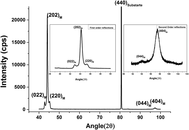
Figure 1 shows the x-ray diffraction (XRD) pattern recorded with a two circle goniometer equipped with parallel beam optics. The triplet observed in the XRD pattern reveals the presence of martensite phase in the as-deposited films. The martensite phase of the film as determined from the XRD pattern, has a distorted orthorhombic crystal structure with lattice parameters: a = 6.1 Å, b = 5.85 Å, c = 5.51 Å, α = β = 90° and γ = 90.45° (space group: Pnnm). The overall intensity of the peak in θ − 2θ measurement provides an indirect estimation of the volume fraction of the planes parallel to the surface. Two high intensity reflections from the first order (202)7M and second order (404)7M observed in the conventional θ − 2θ scan indicate a (101) preferred orientation in the film. However, two small intensity peaks of (220)7M and (022)7M observed at 42.7° and 45.3° (inset of Fig. 1) eliminate the possibility of the single crystalline nature of the film and indicates the presence of multiple variants in the film. It is reported that with increasing thickness, preferred orientation in polycrystalline Ni–Mn–Ga films shows transition from surface energy minimization texture i.e., (110) to strain energy minimization texture (100). Reference Dunand and Müllner33 However, in the present case, the film is highly oriented and the (101) orientation of the as-deposited films is determined by the lower lattice mismatch between the film and the substrate. The x-ray diffraction results reveals that long c-axis and short a-axis of the orthorhombic martensite have preferred alignment along the in-plane, whereas, the higher intensity of (101) reflection indicates the preferred alignment of b-axis normal to the substrate.
X-ray diffraction pattern of NiMnGa film: pattern indicates orthorhombic martensite phase with strong (202) orientation and small intensities from (022), (220) and (044) peaks in the insets of Fig (1).

B. Crystallographic texture and crystal quality of the film
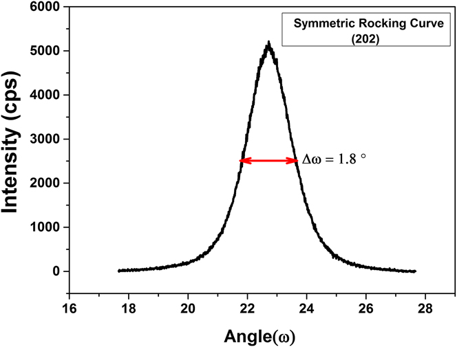
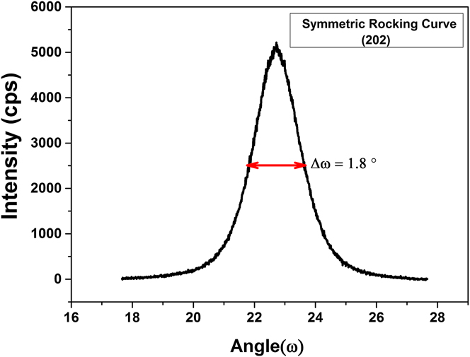
The crystal quality of the epitaxially grown thin films was characterized by performing rocking curve measurements. The amount of tilt and twist boundaries in the films is often associated with the broadening of symmetric and asymmetric rocking curves. Reference Hordon and Averbach34 Figure 2 shows the symmetric rocking curve from the (202)7M reflection, and full width at a half maximum (FWHM) of 1.8°. This value is quite high for epitaxial growth; however, it still indicates an excellent alignment of mosaic blocks in the film. The higher mosaicity in the film is the result of local epitaxial growth due to higher incident flux, presence of multiple variants and insufficient ad-atom mobility during the growth of the film in Zone T conditions. Reference Petrov, Barna, Hultman and Greene35 Furthermore, the presence of a highly symmetric peak with a typical Gaussian profile, as shown in Fig. 2, indicates the presence of a homogenous strain in the films. If the screw dislocations are considered as randomly distributed, the following equation yields the screw dislocation density N Screw from the FWHM of the symmetric rocking curve, Reference Gay, Hirsch and Kelly36
 $${N_{{\rm{screw}}}} = {{{\beta ^2}} \over {4.35 \times b_e^2}}\quad ,$$
where β is the FWHM of the symmetric rocking curve and b
e is the burger vector
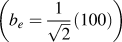 $\left( {{b_e} = {1 \over {\sqrt 2 }}\left( {100} \right)} \right)$
for screw dislocation. The screw dislocation density in the film is determined to be 1.34 × 1011 cm−2.
X-ray rocking curves for a symmetrical (202)7M reflection of an orthorhombic martensite phase.
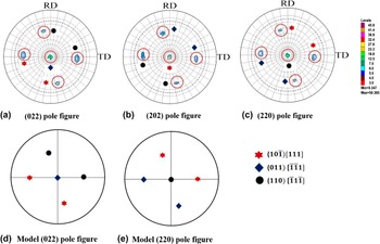
The x-ray diffraction pattern as a θ – 2θ scan only indicates a strong (101) preferred out-of-plane orientation in the film. To get complete information about the crystallographic texture i.e., texture strength and texture components, pole figure measurements were performed in the as-deposited film. The spot like distribution of poles in the film, as shown in Fig. 3, reveals both out-of-plane as well as in-plane preferred orientation in the film. These poles are the different martensitic variants present in the film and could be indexed as
 $\left( {10\bar 1} \right)$
[111], (011)
 $\left[ {\bar 1\bar 11} \right]$
, and (110)
 $\left[ {\bar 11\bar 1} \right]$
, respectively, using a standard stereographic projection generated by JEMS software.
Reference Stadelmann37
The high intensities and the sharp distribution of the poles indicate an excellent crystal quality with lower orientation spreading in the film.
(a) (022)7M, (b) (202)7M, (c) (022)7M pole figures measured from the martensite phase of the film and (d–e) (220) and (022) model pole figures showing the corresponding texture components.

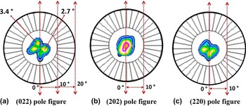
In addition to these sharp reflections, a 4-fold splitting has been observed in the (220)7M and (022)7M pole figures near to center, as shown in Fig. 4. This indicates that these planes are tilted from the normal direction by angles 3.4° and 2.7° respectively. The 4-fold splitting and the tilt of the (220) and (022) planes could be explained by considering the presence of a retained austenite layer at the film substrate interface. In the case of the (202)7M pole figure, no splitting of poles is observed. This suggests that the (202) plane of the martensite is nearly parallel to the (220) plane of the parent austenite, and, hence, contributes to the maximum intensity in the θ – 2θ scan. The slight variation in the intensity, and distortion in the 4-fold symmetry is related to the alignment of the sample during the measurement. The other possible reason for the observed 4-fold splitting in the (220) and (022) pole figure is the alignment of different martensitic variants transforming from single crystal austenite cubic phase. In the previous reports, Cong et al. Reference Cong, Zhang, Esling, Wang, Lecomte, Zhao and Zuo38,Reference Cong, Zhang, Wang, Humbert, Zhao, Watanabe, Zuo and Esling39 have observed the 4-fold splitting in (001) pole figure from multiple martensitic variants present in nonmodulated tetragonal martensite phase. Yang et al. Reference Yang, Zhang, Li, Qin, Esling, Zhao and Zuo40 have also observed the splitting of poles in (040) pole figure due to the presence of multiple variants in epitaxial 7M orthorhombic NiMnGa thin film on MgO (100) substrate. However, no indication of 4-fold symmetry has been observed in the measured pole figures.
The (022)7M, (202)7M, and (022)7M pole figures of the film with 4-fold splitting near the center. The circles are shown for each ∆ϕ = 10°.

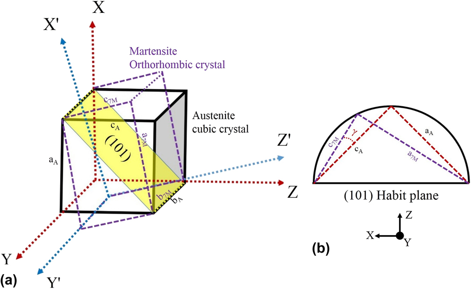
Earlier reports, Reference Thomas, Heczko, Buschbeck, Rößler, McCord, Scheerbaum, Schultz and Fähler14 on the 4-fold splitting at the center of the (400) and (004) poles in the pole figure attribute the same to the hindrance of the martensitic transformation by a rigid substrate and the presence of some retained austenite at the interface. The presence of 4-fold splitting in the pole figure is a result of the tilt between the martensite and the austenite planes present at the interface. The schematic representation of the formation and calculation of the tilt between retained austenite and martensite planes is given by a simple geometric model as shown in Fig. 5. Figure 5(a) display the schematic representation of retained austenite unit cell present at the interface between film and substrate, transformed martensite orthorhombic unit cell and the undistorted/invariant (101) habit plane between the two crystals. The bulk experiments results from Brown et al. Reference Brown, Dennis, Crangle, Kanomata, Matsumoto, Neumann, Justham and Ziebeck41 shows that the habit plane between austenite and martensite is close to (101). From the geometrical model shown in Fig. 5(b), the tilt angle ‘γ’ between the martensite and the retained austenite plane can be calculated using the equation given below.
 $$\gamma = 45^\circ - \arctan \left( {{{{a_{\rm{M}}}} \over {{c_{\rm{M}}}}}} \right)\quad .$$
(a) Schematic representation showing the retained austenite unit cell, transformed martensite unit cell and the undistorted/invariant (101) habit plane between the two crystals, (b) geometrical model showing the tilt angle between the austenite and martensite plane.

Using the values of the lattice constants calculated from the x-ray diffraction, the tilt angle calculated from the equation above is 3.0°, which is very close to the values measured by the experimental pole figures, as shown in Fig. 4. The difference in the calculated and measured values of the pole figure could be attributed to the monoclinic distortion in the unit cell which was not considered during the calculation of the tilt angle.
C. Microstructural features
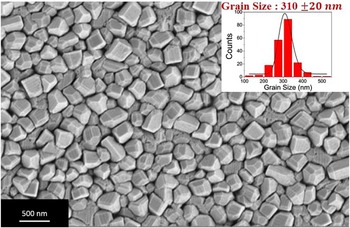
The microstructure of the film and the grain size distribution were examined with secondary electron imaging in a field emission scanning electron microscope (FESEM). Figure 6 shows that the film exhibits a highly faceted morphology with a nonspherical granular microstructure. The low ad-atom mobility and overgrowth mechanism are the possible mechanisms for the formation of facets on the surface. The average grain size is estimated to be 310 ± 20 nm from the log-normal distribution, as shown in the inset of Fig. 6. Almost 250 grains were covered to get a better statistical distribution of grain size in the film. On the surface of the film, a strip like pattern of width ∼50–100 nm is also visible. The topographic contrast on the surface arises from the surface relief due to the presence of martensitic micro-twins in the film. These surface relief features are not continuous and coherent throughout, but change direction from one grain to another. The presence of large in-plane (twist boundaries) and out of plane (microscopic tilt) orientation spread and presence of multiple variants in the film are possible reasons for the random alignment of the twins in the film (as indicated by the large full width half maximum of a symmetric rocking curve).
FE-SEM image showing a highly faceted granular microstructure with columnar growth and a grain size of 310 nm. The grain size distribution is shown in the inset.

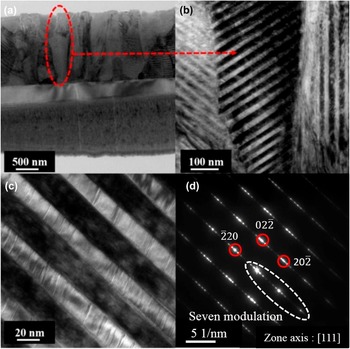
Figure 7 shows the transmission electron micrographs of the Ni–Mn–Ga film obtained from a cross-sectional sample prepared by FIB milling. The micrograph shown in Fig. 7(a) reveals a columnar growth of the film with an average lateral coherence length of 300 nm. These columns are separated by well-defined grain boundaries and consist of martensitic primary twinned variants. The orientation of an individual column is not the same throughout the thickness and consists of small and high angle grain boundaries. The high magnification image shown in Fig. 7(b) is acquired from a selected region from one of the column [Fig. 7(a)]. The microstructural features displayed in Fig. 7(b) reveal martensitic twin variants, which are formed by adaptive modulation within the column. The width of the nano-twins variant was estimated to be in the range of 50–75 nm. The nano-twinned region, when observed at a higher magnification, reveals staircase-like features with modulation in the stacking [Fig. 7(c)]. Khachaturyan et al.
Reference Khachaturyan, Shapiro and Semenovskaya42
have reported that the appearance of adaptive martensite is expected if the energy of the twin boundary between the two martensitic variants is very low, and elastic energy at the interface between austenite and martensite is high. The martensite phase, in that case, forms a coherent structure consisting of lamellae with periodic stacking, as observed in Figs. 7(b)–7(c). In seven modulated (7M) orthorhombic Ni–Mn–Ga martensite phase,
 $\left( {5\bar 2} \right)$
stacking results in the formation of secondary nano-twins within the primary martensitic twin variants.
Reference Pons, Santamarta, Chernenko and Cesari43
The ease of reorientation of these low energy nano-twin boundaries in the presence of a magnetic field promotes the ferromagnetic shape memory effect in the film. The twin boundary present between the two variants is highly distorted, and not a sharp boundary. This implies that the interface is highly incoherent and probably consist of stacking faults that might have been generated at the twin interface during the martensitic transformation. The selected area electron diffraction (SAED) pattern, as shown in Fig. 7(d), acquired from the martensitic variant, consists of six low intensity diffraction spots within the main bright fundamental diffraction spots. This confirms the presence of seven modulated martensite phase in the film. The SAED pattern obtained can be indexed to the [111] zone axis of the seven modulated (7M) orthorhombic martensite phase of Ni–Mn–Ga.
Transmission electron microscopy images of NiMnGa film (a) Columnar growth in the film (b) presence of nano-twins within the column (c) high magnification image from nano-twins shows staircase like structures within the twins (d) selected area electron diffraction (SAED) pattern shows seven modulated diffraction pattern from the orthorhombic martensite phase.

Figure 8(a) shows a high magnification bright image of the martensitic variants separated by the twin boundaries in the film. The thickness of the primary martensitic variant is determined to be 40 ± 2 nm. Within a martensitic variant, a clear signature of modulation in stacking due to the presence of secondary nano-twins, is observed. The high resolution transmission electron microscopy (HRTEM) image Fig. 8(b) shows a layered contrast in the variant (indicated by arrowheads) and indicates that the structure is modulated. The width of the secondary nano-twins is determined to be ∼1.5–2.0 nm from the HRTEM image. The six satellite spots are visible in the Fast Fourier Transform (FFT) pattern generated from the HRTEM image [inset Fig. 8(b)] confirm the presence of secondary nano-twins with 7M adaptive martensite structure in the film.
(a) The high magnification bright field image of martensitic variants showing twin boundaries and modulation in the stacking and (b) The HRTEM image of the variant shows the presence of secondary nano-twins. The corresponding FFT shows six satellite spots, characteristic of seven modulated adaptive martensite.

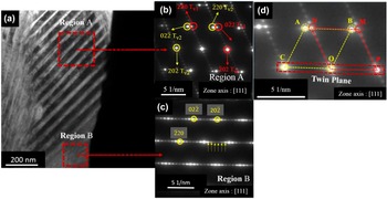
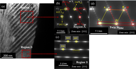
Further investigations of microstructure using transmission electron microscopy reveal the existence of multiple variants along the thickness of the single column in the film. The bright field image shown in Fig. 9(a) of the column clearly indicates two different microstructural regions present within the column. The SAED pattern from the corresponding regions shows seven modulated pattern corresponding to the orthorhombic martensite and can be indexed with the zone axis as [111]. The SAED pattern from region ‘A’ shown in Fig. 9(b) is rotated by nearly 62° degree with respect to the SAED pattern obtained from region ‘B’ [Fig. 9(b)]. The six satellite spots present within the main diffractions spots are indicated by an arrow heads in Fig. 9(c). Further analysis of diffraction pattern from region ‘A’ reveals the presence of twin variants. The ABOC and MNOP spots in the selected area diffraction pattern from region ‘A’ shown in Fig. 9(d) represent two twin variants with (202) twinning plane. It is also observed from Figs. 9(b) and 9(c) that the satellite spots formed due to adaptive martensite are only present in variant 1 and are completely absent in the twin variant 2.
(a) The bright field showing the two distinct microstructural region along the thickness of the column, (b) corresponding SAED pattern from the region ‘A’, (b–c) region ‘B’ showing two martensitic variants are present with in the column and (d) SAED pattern from micro-twin with twin variants [‘ABOC’ twin variant 2 (yellow) and ‘MNOP’ twin variant 1(red)] and twin plane ‘COP’ (202).

D. Magnetic properties of the film
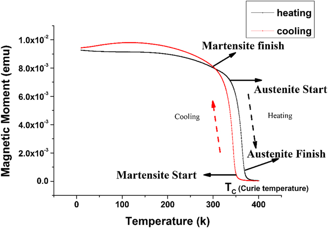
Temperature dependent magnetization was studied using a SQUID. Figure 10 shows the change in magnetization of as-deposited films with temperature. The measurements were carried out during heating and cooling cycles at a constant applied field of 100 Oe. The change in the slope of the magnetization–temperature curve is an indication of the onset of phase transformation in the material. The deviation in the magnetization curve at 345 K indicates the occurrence of austenite (cubic) to martensite (orthorhombic) first order structural transformation in the film. The four characteristic transformation temperatures M s, M F, A S, and A F, as indicated by arrows in Fig. 10, were determined by finding the maximum change in the slope of the curves using a conventional tangent method: M S = 353 K, M F = 304, A S = 335 K and A F = 372 K. A small thermal hysteresis of about 18° is observed in the heating and cooling cycles during the temperature-dependent magnetization measurements. The low value of the thermal hysteresis observed in the films is quite useful for actuation-based device applications. The sharp decrease in the magnetization curve at approximately 385 K corresponds to the Curie temperature (T C), where the material starts lose its ferromagnetic ordering and becomes paramagnetic. The characteristic jump in magnetization Reference Jakob and Elmers26 during austenite to martensite is absent in the temperature dependent magnetization curve in the present investigation. This could be attributed to the near co-occurrence of structural (austenite → martensite) and magnetic transformation (ferromagnetic → paramagnetic) temperatures in the film.
Magnetic moment versus temperature curve showing the temperature dependent magnetization plot for NiMnGa thin film during the heating and cooling cycles. The arrows in the figure indicates the four characteristic temperatures of the transformation sequence.
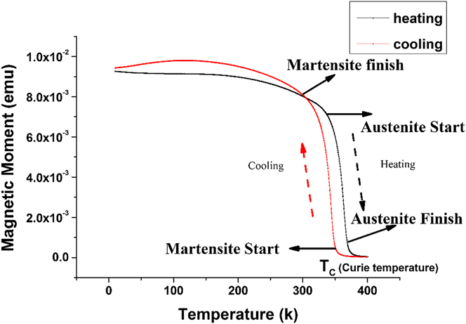
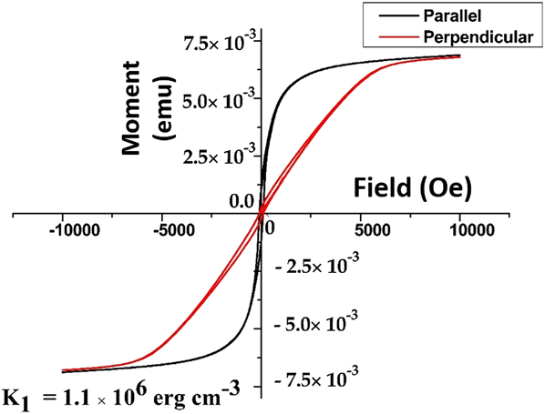
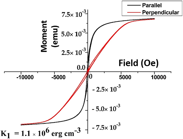
Figure 11 shows the magnetization versus the applied magnetic field plot for the film with the field direction perpendicular and parallel to the film surface. The value of anisotropy energy is determined to be 1.1 × 10⁶ erg/cm3 using the equation K 1 = H A M S/2 used for materials having strong in-plane magnetization. Reference Johnson, Bloemen, Den Broeder and De Vries44 The values obtained are approximately in agreement with the values reported by Heczko et al. Reference Straka, Heczko and Ullakko45 for a single crystal of the orthorhombic martensite phase (1.7 × 10⁶ erg/cm3). The saturation magnetization in the film is determined to be 42 emu/g when considering the bulk density as 8 gm/cm3. The value is 70% of the saturation magnetization (64 emu/g) value reported for bulk single crystals of Ni–Mn–Ga. The magnetic field induced reorientation effect characterized by an abrupt jump in magnetization versus field plot Reference Heczko, Jurek and Ullakko46 is not observed in the present sample. The absence of the MIR effect could be attributed to the constraint effect of the substrate, high level of defect density, high twinning stresses due to the presence of multiple martensitic variants and the texturing effect in the as-deposited film. Reference Zhang, Hughes, Britten, Preston, Botton and Niewczas47 However, a higher saturation magnetization, magnetic anisotropy, and low thermal hysteresis make this film a potential candidate for actuation based applications.
Magnetization versus applied field hysteresis (M–H Plot) with field parallel (H ∥) and perpendicular (H ⊥) to the film. The anisotropy energy constant K 1 is determined to be 1.1 × 10⁶ erg/cm3 .
E. Study of phase transformation in situ
An in situ investigation of phase transformation was carried out by performing the high temperature x-ray diffraction measurements on the as-deposited films. Figure 12 shows the high temperature XRD patterns recorded at different temperatures, ranging from room temperature to 413 K, and, again, at room temperature. Since the aim of this experiment was to capture the transformation of the martensite to the austenite phase with temperature, the scan range selected was from 40° to 48°. In this range, a change in the orthorhombic triplets corresponding to the martensite planes (022), (202), and (220) with an increase in temperature was noticed. It was observed that till 343 K, there was no indication of phase transformation in the material as all the three peaks corresponding to orthorhombic martensite triplets were present in the XRD pattern. However, an further increase in temperature to 353 K, the first indication of phase transformation was observed as the triplet peak transformed to a single peak at 43.8°, which corresponds to the (220) plane of the cubic austenite phase. An increase in intensity and a decrease in the full width at half maximum of the peak was observed with an increase in temperature upto the transformation temperature. Thereafter, the values remained constant.
In situ high temperature XRD studies carried out on the film from room temperature to 413 K and at room temperature after cooling. The red line corresponds to the (202)7M peak position and blue line is for (220)A.

The measurements performed on the film after cooling to room temperature show the re-appearance of the triplet peak of the martensite phase (Fig. 12). This is an indication of the reversible phase transformation process in the film. It is to be noted that the slope change of the magnetization curve, as observed during the temperature dependent-magnetization measurements (Fig. 10), lies in the same temperature range. The transformation temperature observed in the film is higher than the temperature predicted by using the e/a ratio. Reference Jin, Marioni, Bono, Allen, O'Handley and Hsu20 The presence of residual stress in the film which originates due to the difference in the thermal expansion coefficients between the substrate and film could be the reason for the shift of transformation temperature to a higher value.
IV. CONCLUSIONS
In the present work, a systematic study has been performed to examine the structure, microstructure, texture, and magnetic properties of oriented seven modulated martensite Ni–Mn–Ga thin films with multi-variant structure deposited on an Al2O3
 $\left( {11\bar 20} \right)$
substrate. The key conclusions of this investigations are as follows:
-
(1) The lower lattice mismatch between the film and substrate results in a growth of highly oriented Ni–Mn–Ga thin films with a (202) preferred orientation. A combination of deposition condition and substrate selection provides an ideal condition for the development of both in-plane and out-of-plane preferred orientation in the film. The 4-fold splitting near the center of the (220)M and (022)M measured pole figure indicates the presence of retained austenite and martensitic variants at the interface.
-
(2) Microscopic investigation performed on the film reveals a highly faceted growth with a grain size large enough to accommodate martensite twins within. The presence of a ferromagnetic martensite phase at room temperature and adaptive nano-twins satisfies all the preconditions for the ferromagnetic shape memory effect. However, the presence of a high defect density, a large number of grain boundaries and texturing effect in the as-deposited film suppress the magnetic field induced reorientation effect.
-
(3) In spite of the absence of a magnetic field induced reorientation effect, a thermally induced phase transformation has been observed in the present film with in situ high temperature x-ray diffraction and temperature dependent-magnetization measurements. The reversible structural (martensite to austenite) transformation and magnetic transition (ferromagnetic to paramagnetic) occur at temperatures (T C) 345 and 385 K respectively.
ACKNOWLEDGMENTS
This work was sponsored by Department of Information Technology (DietY), MCIT, Govt. of India. We acknowledge Dr. S.V Kamat and Dr. Manivel Raja (Defense Metallurgical Research Laboratory, Hyderabad, India) for providing sputtering target for the present work. The characterization of as deposited films were carried out at Micro and Nano Characterization Facility at Center for Nano Science and Engineering and AFMM, Indian Institute of Science. The author is also thankful to Prof. Rajeev Ranjan for allowing to use the X-ray facility for this work.