1. INTRODUCTION
Military and industrial applications stimulate intense interests in high-voltage pulse generators with high average power, high repetitive rate capability and long pulse achievability, which have been widely used in the fields of high-power microwave (Benford et al., 1993; Korovin et al., Reference Korovin, Rostov, Polevin, Pegel, Schamiloglu, Fuks and Barker2004; Qian et al., Reference Qian, Li, Liu, Zhang, Liu and Liu1998; Zhang et al., Reference Zhang, Jin, Yang, Zhong, Shu, Zhang, Qian, Yuan, Li, Fan, Zhou and Xu2011; Qi et al., Reference Qi, Zhang, Zhong, Zhang and Zhu2014), high-energy pulse laser (Cook et al., Reference Cook, Ball and Birx1991), plasma science (Ruma et al., Reference Ruma, Hosseini, Yoshihara, Akiyama, Sakugawa, Lukes and Akiyama2014), beams surface treatments (Barrett et al., Reference Barrett, Cockreham, Dragt, White, Neau, Reed and Ives1999; Mueller et al., Reference Mueller, Bluhm, Heinzel, An, Berghoter, Delgiacco, Eing, RFetzer, Flickinger, Frey, Giese, Gottel, Gusbeth, Heinzel, Hoppe, Jianu, Lang, Leber, Sack, Schuhmacher, Singer, Straessner, Wegner, Weisenburger, Zimmermann and Engelko2011), electroporation (Sack et al., Reference Sack, Eing, Stängle, Wolf, Mueller, Sigler and Stukenbrock2009), etc. (Zhang et al., Reference Zhang, Jin, Yang, Zhong, Shu, Zhang, Qian, Yuan, Li, Fan, Zhou and Xu2011). As one of the concernful trends, long duration pulse generators based on solid-state power devices can hold and accumulate more energy on various loads with the same power level, steadily and continuously. In addition, these generators have potential for high repetitive rate and long lifetime operating, which is of importance to the performance of the whole application system (Harjes et al., Reference Harjes, Reed, Buttram, Turman, Neau, Martines, Adcock, Weinbrecht, Mann, Morgan, Laderach, Pena, Butler, Schneider, Wavrik, Penn and Weber1990; Zhang et al., Reference Zhang and Liu2013; Jiang et al., Reference Jiang, Yatsui, Takayama, Akemoto, Nkamura, Shimizu, Tokuchi, Rukin, Tarasenko and Panchenko2004). Therefore, interested in generating reliable long duration pulses with solid-state power devices, we are motivated to study the high-voltage, long-pulse generator based on magnetic pulse compressor, Blumlein-type rolled strip pulse forming line (RSPFL) and inductive voltage adder (IVA).
In the present paper, a new technical scheme of high-voltage, long-pulse generator based on magnetic pulse compressor and low-impedance RSPFL was presented and investigated to achieve reliable long-duration pulses for fitting of various applications. Specifically, a two-stage magnetic pulse compressor was utilized to modulate pulses for the fast charging of the solid-state pulse-forming line which have higher breakdown voltage when charging with shorter time. Rise time of the pulses was compressed from 11.8 to 3.2 μs, then to 1.2 μs, and the operating voltage was about 40 kV with efficiency up to 92%. The Blumlein-type RSPFL was composed of two traditional RSPFLs with proper connections. For each of them, the impedance and the electrical length are 1.5 Ω and 100 ns with the dimensions and the weight of approximately Φ 300 × 250 mm and 15 kg, respectively. High-voltage cables were used for the connection between main switch and IVA. The IVA was employed for increasing the voltage level and impendence transformation. Typical quasi-square pulse with output current of 2.3 kA was obtained on a dummy load. As the resistance of the load was measured to be 60 Ω, the peak voltage was approximately 138 kV. Pulse duration [full wave at half maximum, (FWHM)] of the generator was over 200 ns.
The remainder of the present paper is as following. In Section 2, considerations and operating process of the high-voltage, long-pulse generator are discussed. In Section 3, design and manufacture of the mentioned sub-systems are described in detail. Based on the analysis, a full circuit model is established via P-Spice software in Section 4. Accordingly, experimental study on the high-voltage, long-pulse generator is presented. Conclusions are stated in Section 5.
2. CONSIDERATIONS OF THE HIGH-VOLTAGE, LONG-PULSE GENERATOR BASED ON MAGNETIC PULSE COMPRESSOR AND RSPFL
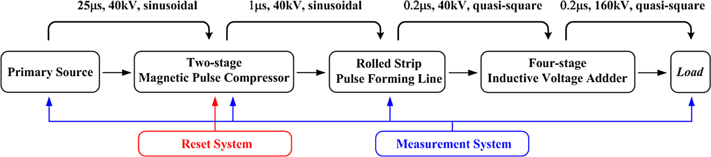
In order to achieve reliable pulses with the FHWM of over 200 ns for wider applications, the RSPFL is selected due to its compact structure and well performance according to our former investigations (Li et al., Reference Li, Qian, Yang, Gao and Liu2013). Due to the utilization of large trans. ratio pulse transformer in the primary source, rise time of the output voltage from primary source is over tens of microseconds. It is inappropriate for directly charging for RSPFL considering the insulation characteristics of solid-state dielectric (Schamiloglu, Reference Schamiloglu2003; Yang et al., Reference Yang, Zhong, Qian and Yang2011). Consequently, a two-stage magnetic pulse compressor is needed to decrease the charging time for RSPFL. Working at the front stage of the generator, the device can steadily achieve high-energy efficiency. As the operating voltage is relatively low, the self-close spark gap with compact structure can be used as the main switch, reliably. As the charging time is short enough, this switch can be changed to magnetic switch for achieving all solid-state pulse generators. Coaxial cables are used for flexible connection to different cells of IVA with little stray inductor. For achieving high-voltage pulses, a four-stage IVA is utilized with azimuthal transmission line. Solution of CuSO4 is used as the dummy load for the high-power capability. Reset and measurement system are used at proper place. The block diagram of the proposed high-voltage, long-pulse generator is shown in Figure 1.
Block diagram of the long-pulse, high-voltage generator.
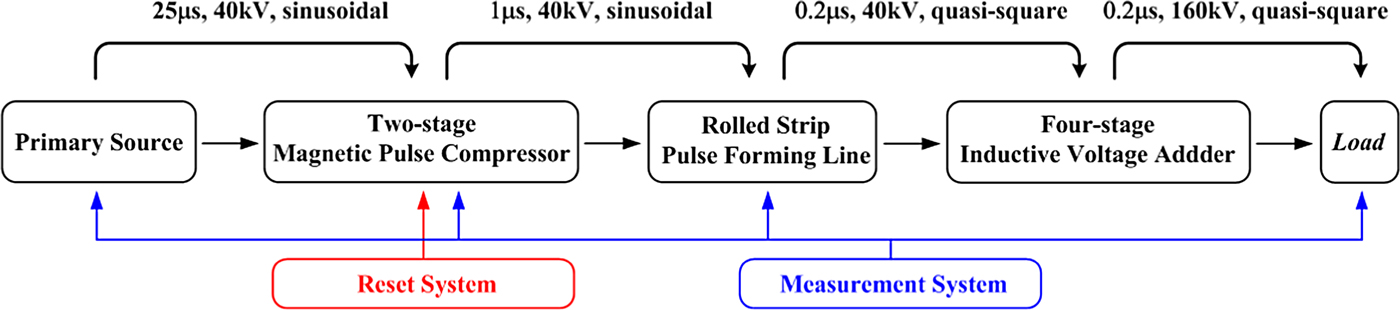
As the low-impendence RSPFL is used for generating long-duration pulses, sub-systems before the IVA is operating under low-voltage – high-current mode, relatively, for achieving high-power level. Then, the peak voltage of quasi-square pulses is increased by IVA to increase the voltage level and fulfills wider applications. Operating process of the long-pulse, high-voltage generator can be described as following. Initially, a (1−cosωt)-type pulse, generated by the primary source, is compressed by the magnetic pulse compressor for fast charging of the low-impendence RSPFL. After the RSPFL is fully charged, the main switch is closed. Quasi-square pulse formed in the RSPFL is propagated to the IVA cells for voltage stepup via coaxial cables. Finally, all the energy is accumulated on the dummy load.
3. DESIGN AND MANUFACTURE OF THE SUB-SYSTEMS OF THE GENERATOR
In our high-voltage, long-pulse generator, the FWHM and peak voltage of the typical quasi-square pulse is required to be over 200 ns and 120 kV, respectively. Accordingly, design and manufacture of the sub-systems of the generator are described in detail.
3.1. Two-stage Magnetic Pulse Compressor
The magnetic pulse compressor, also known as Melville Line, is a powerful device which is used to generate pulses with fast rise time at high-energy efficiency (Melville, Reference Melville1951). Considering the insulation characteristics and the requirement of output voltage, the output voltage from the primary source is designed to be 40 kV. It is generally believed that fast charging of the solid-state pulse forming line have higher breakdown voltage (Nunnally, Reference Nunnally1981). Therefore, the rise time of the charging pulse is designed to be shorter than 1 μs. As the rise time of the output pulses from primary source is approximately 12 μs, the total compression ratio is approximately 12. Limited by the performance of the magnetic cores, two stages, with radio of 4 and 3, respectively, are needed for achieving the compression process.
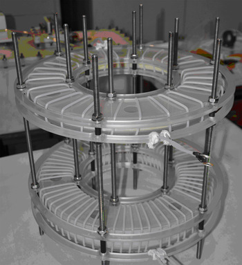
Iron-based amorphous cores, shown in Figure 2, were chosen to set up the magnetic switch. Key parameters of them are shown in Table 1. At the same time, high-voltage cables with the breakdown strength of over 50 kV and rein-forcer made by Plexiglas was employed for the insulation and safety considerations.
Iron-based magnetic core utilized in the generator.

Key parameters of the magnetic cores

A m is the cross-sectional area of the magnetic material; ΔB the flux induction change; α the stacking factor, β the packing factor; δ the thickness of the material; and l a the average length of magnetic path.
According to the characteristics of the components, electrical parameters of the two-stage magnetic pulse compressor are calculated, as indicated in Table 2, with the following equations (Barrett, Reference Barrett1995).
 $${\rm \Phi} = \int_0^{{{\rm \tau} _{\rm s}}} {V\left( t \right)\,} {\rm d}t = {N_{\rm m}}{\rm \Delta} B{A_{\rm m}},$$
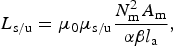 $${L_{{\rm s/u}}} = {{\rm \mu} _0}{{\rm \mu} _{{\rm s/u}}}\displaystyle{{N_{\rm m}^2 {A_{\rm m}}} \over {{\rm \alpha} {\rm \beta} {l_{\rm a}}}},$$
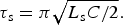 $${{\rm \tau} _{\rm s}} = {\rm \pi} \sqrt {{{{L_{\rm s}}C} / 2}}.$$
Electrical parameters of the two-stage magnetic pulse compressor

Here, Φ is the flux in the magnetic switch; τs is the rise time of the charging pulse; V(t) is the charging voltage with peak amplitude of V 0; N m represents the turn number of the windings; L s/u and μs/u are the inductance and permeability of the saturable and unsaturable states, respectively; and μ0 is the permeability of the vacuum. All the capacitors have the same capacitance (C k).
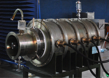
The magnetic switches of the two-stage magnetic pulse compressor are shown in Figure 3.
The two-stage magnetic pulse compressor.

3.2. RSPFL
Generally speaking, the RSPFL consists of copper ribbons and solid insulating films, which are rolled into a cylinder according to some certain ratio and sequence of those ribbons and films (Wang, Reference Wang2009; Li et al., Reference Li, Qian, Yang, Gao and Liu2013). Proper combination of two traditional RSPFLs can work as the Blumlein-type pulse forming line (PFL).
After fully consideration, the Mylar film, with the relative permittivity (εr) of about 2.3 and the breakdown electric strength of over 600 kV/cm, was selected as the insulation dielectric. For each traditional RSPFL, the thickness of the dielectric films depends on the characteristic impedance and the breakdown strength of the RSPFL, indicated by following equation (Yang et al., Reference Yang, Zhong, Qian and Yang2010).
 $$Z = \displaystyle{{30{{\rm \pi} ^2}} \over {\sqrt {{{\rm \varepsilon} _{\rm r}}}}} {\left[ {1 + \displaystyle{{{\rm \pi} W} \over b} + \ln \left( {1 + \displaystyle{{{\rm \pi} W} \over b}} \right)} \right]^{ - 1}}.$$
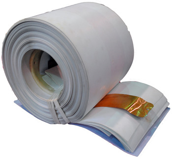
Here Z is the characteristic impedance; W is the width of the copper ribbons; and b is the thickness of the dielectric films. In order to get the impendence of approximately 1.5 Ω, six layers of the Mylar film, with the total thickness of 2 × 6 × 0.2 mm3, were laid between the copper ribbons (W = 80 mm). In the meantime, the design ensures the device operating over 100 kV. Calculated with the propagation formula of the electromagnetic wave in the solid-state dielectric (Xia et al., Reference Xia, Zhang, Shi, Zhang, Deng, Liu and Cao2008), the length of the copper ribbons and insulators should be over 20 m to achieve the pulse duration over 200 ns. Rolling on a polymer cylinder with diameter of 110 mm, the traditional RSPFL are shown in Figure 4.
The traditional RSPFL unit for Blumlein-type PFL.

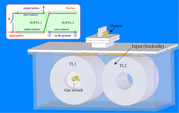
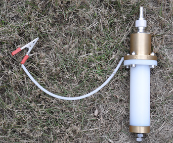
As all the components of the RSPFL were immerged into the transformer oil for further insulation, the main switch, as shown in Figure 5, was designed to be a self-closed spark gap with sealed rounded plate electrodes. Dimension of the electrodes is Φ 30 × 10 mm2 and the maximum working voltage is over 100 kV when filled with SF6 gas. Connection of the two traditional RSPFL is also detailed in Figure 5.
Structure of the Blumlein-type RSPFL and main switch.

3.3. IVA, Dummy Load, and Test Devices
In order to improve the peak voltage of the pulses output from RSPFL, a four-stage IVA is employed to increase the voltage level in our generator (Smith, Reference Smith2004; Meng et al., Reference Meng, Qian and Yang2011). In consideration of the structure of the high-voltage generator, pulses from RSPFL were fed to each cell at a single point. For a better uniformity, an azimuthal transmission line, made by brass, distributes the inspirit current to four connection points on the high-voltage end of the induction cavity.
High-voltage coaxial cables were utilized to achieve pulse propagation from RSPFL with microstrip line structure to the IVA's input port with coaxial structure. The breakdown electric strength of the cables is approximately 50 kV. Established IVA is shown in Figure 6.
Four-stage IVA.

The cylinder dummy load, with dimensions of Φ 90 × 200 mm2, was manufactured for the consideration of power capability. As the CuSO4 water solution has sensitive change with the temperature and dissolution time, dummy load was manufactured several hours before experimental study. Fast responsive water resistance divider and Rogowski coil are used to detect the high-voltage and current at key points of the generator. Figure 7 shows the developed water resistance divider.
Water resistance divider.

4. CIRCUIT SIMULATION AND EXPERIMENTAL STUDY OF HIGH-VOLTAGE, LONG-PULSE GENERATOR
4.1. Circuit Simulation on the High-voltage, Long-pulse Generator
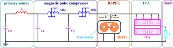
Based on the above-mentioned design, a full circuit model of the high-voltage, long-pulse generator was established and investigated in P-Spice software according to the real device. The circuit schematic is shown in Figure 8. Here, the primary source is composed by the primary capacitor C 0 and resonance inductor L. C 1, C 2 and MS 1, MS 2 are the capacitors and magnetic switches which belong to different stages of the magnetic pulse compressor. RSPFL describes the Blumlein-type RSPFL formed by two traditional RSPFLs. IVA presents the four-stage IVA. Z is the dummy load.
Circuit schematic of the high-voltage generator.

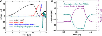
A group of typical simulation results are shown in Figure 9. Charging voltage of C 1, C 2, RSPFL, and discharging voltage from RSPFL are indicated in Figure 9a. Current flowing through the dummy load is described in Figure 9b. The extended discharging voltage from RSPFL is also shown here for a clear view. It could be observed that the compression radio of the two-stage magnetic pulse compressor is about 12, with 4 and 3 in different stages. The charging time of the RSPFL is approximately 1 μs which is suitable for our design. Rise time of the output voltage from RSPFL is approximately 80 ns. When the initial peak voltage on C 0 is 40 kV, typical quasi-square pulse with FWHM of 200 ns, current over 2.3 kA is obtained on the dummy load. The simulation results meet the theoretical analysis well.
Typical simulation results of the high-voltage pulse generator based on the magnetic pulse compressor and RSPFL.

4.2. Experimental Study on the Long-pulse, High-voltage Generator
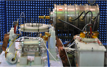
Based on the above-mentioned results, a long-pulse, high-voltage generator, as indicated in Figure 10, was set up in our laboratory according to the circuit shown in Figure 8.
High-voltage, long-pulse generator based on the magnetic pulse compressor and RSPFL.

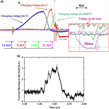
At the charging voltage of 40 kV from the primary source, typical experimental results are shown in Figure 11. As indicated in Figure 11a, the two-stage magnetic pulse compressor provides pulses with the peak voltage of approximately 40 kV, rise time compressed from 11.8 to 3.2 μs, and then to 1.2 μs with voltage efficiency over 92%. Additional, the low-impedance RSPFL can successfully generate quasi-square pulse with duration over 200 ns. Rise time of the output voltage from RSPFL is approximately 85 ns due to the equivalent inductance of the main switch. Figure 11b shows the waveform of the current flowing in dummy load. It is observed that the peak amplitude is up to 2.3 kA with FWHM of 200 ns. As the resistance of the dummy load was measured to be 60 Ω, the peak voltage is approximately 138 kV. The experiment results basically correspond to theoretical analysis and circuit simulation.
Typical experiment results of the long-pulse, high-voltage generator based on the magnetic pulse compressor and RSPFL.

Based on our analysis, the long rise time of the discharge voltage from RSPFL, shown in Figure 11a, comes from the long distance of the connection structure between output port and coaxial cables. The jitters on the rising edge and flat top, indicated in Figure 11b, are due to the measurement system and some mismatch between characteristic impedance of the coaxial cables and IVA.
5. CONCLUSION
In this paper, a new technical scheme of high-voltage, long-pulse generator, mostly based on solid-state power devices including magnetic pulse compressor, Blumlein-type RSPFL and IVA, is proposed and investigated numerically and experimentally. Specifically, a two-stage magnetic pulse compressor was set up with iron-based amorphous cores. Total compression ratio of the device is approximately 12 and the achieved voltage efficiency is up to 92%. Low-impedance, long-duration Blumlein-type RSPFL was established with characteristic impendence and electrical length of 3 Ω and 100 ns, respectively. Mylar film was selected as the solid-state dielectric. Increased by a four-stage IVA, typical quasi-square pulse was obtained with peak current of 2.3 kA and duration over 200 ns. As the resistance of the dummy load was measured to be 60 Ω, the peak voltage was approximately 138 kV. Experiments show reasonable agreement with numerical analysis.