I. INTRODUCTION
As battery capacities increase and become suitable for the mass market, there is an increasing demand on technologies that are capable of charging electric vehicles (EVs) fast and conveniently. With respect to daily handling, charging represents a main difference between electric and conventional combustion vehicles. As the sector of battery and plug-in hybrid EVs is expected to be the fastest growing segment in the passenger vehicle market, a suitable charging technology is therefore particularly important [1]. For the acceptance of this vehicle segment, convenience will be crucial as the customers are not willing to handle potentially dirty and heavy cables several times a week. That is why wireless charging is regarded as the most promising technique, providing a convenient, automatic, and vandalism-proof charging process.
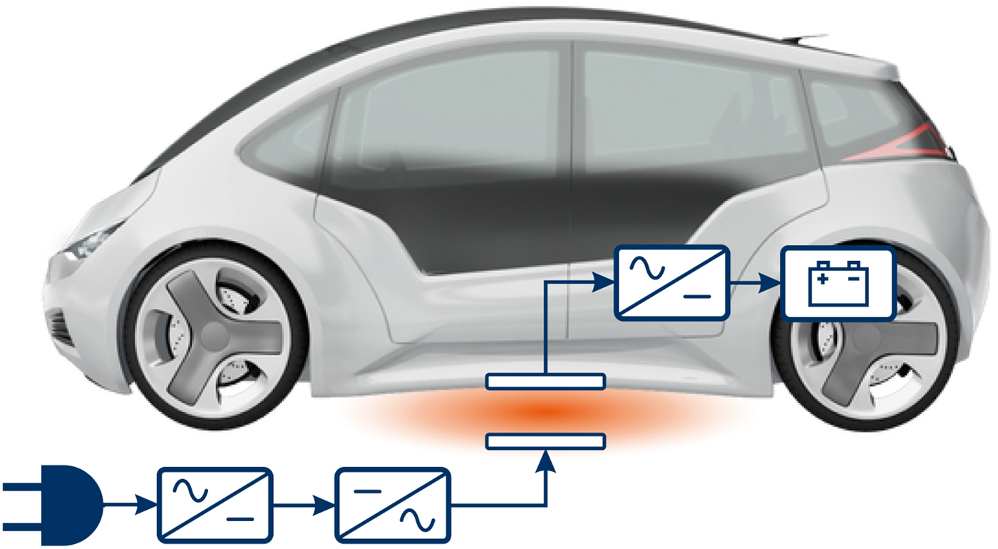
Wireless power transfer is already realized in many low- and mid-power applications such as cell phones, home appliances, automatic guided vehicles, and power tools with transferred powers ranging from 0.1 to 500 W [Reference Kim, Seo, You, Park and Cho2–Reference Hui and Ho4]. In the context of EVs, wireless charging has been developed for almost 20 years [Reference Covic, Elliott, Stielau, Green and Boys5, Reference Boys, Covic and Green6] and its principle is illustrated in Fig. 1. After converting the grid supply to AC at a frequency of 5–150 kHz, the power is transferred between two induction coils via an alternating magnetic field. In contrast to other applications of wireless power transfer, the magnetic field has to pass through a large air gap between the primary and secondary coil. This is associated with many challenges concerning the power transfer itself as well as the strong magnetic field passing through the unsecured area between the charging coils. The EV battery is charged by rectifying the alternating current, which is induced in the vehicle side coil.
Principle of inductive charging for electric vehicles with magnetic field passing through the air gap between the charging coils (orange).
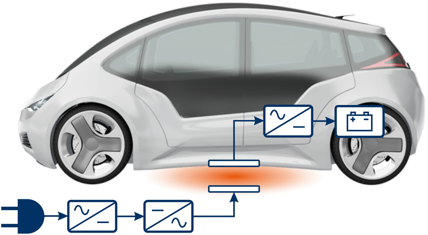
While the limits for exposure to the magnetic stray field besides the car become more difficult to fulfill for greater transmit powers, inductive charging of passenger cars is feasible for powers up to 22 kW [Reference Schumann, Blum, Eckhardt and Henkel7]. However, long-time charging with lower powers will remain the most common mode as power in the range of 3.6–11 kW is available in average households, e.g. in EU and the USA. With a power of 11 kW, even today's largest EV batteries can be fully charged within eight hours. Typical use cases for this kind of charging include the private garage as well as (semi-)public areas like employees’ parking spaces, supermarkets, and automated valet parking.
Especially in publicly accessible parking areas, foreign objects are able to enter the large air gap between the charging coils easily. Eddy currents caused by the alternating magnetic field heat up metallic objects, like coins or screws. Additionally, it is conceivable that living objects enter the hazardous zone between the coils, which must be prevented. As guidelines by the International Commission on Non-Ionizing Radiation Protection (ICNIRP) cannot be met in the area directly between the coils, practical methods are required to prevent living object from being exposed to the magnetic field [Reference Fisher, Farley, Gao and Tse8]. Thus, there is a great interest in developing suitable sensor systems to detect living objects before they enter the hazardous zone so that the charging process can be stopped immediately.
In this work, we propose a new approach using an automotive radar sensor on the vehicle side for living object protection (LOP). In Section II, we describe guidelines concerning the general public exposure to alternating magnetic fields as well as an exemplary sensor arrangement that meets the requirements of inductive charging systems. A prototypical implementation of this sensor arrangement consisting of an idealized vehicle underbody and an automotive radar sensor is described in Section III. Consequently, measurements of practical use cases for LOP systems are presented in Section IV, where two-dimensional signal processing techniques are applied to differentiate between moving and non-moving objects.
II. LOP FOR INDUCTIVE CHARGING
While preventing metallic objects from heating up is sufficient for other applications of wireless power transfer, inductive charging systems for EVs require a special protection system for living objects. The alternating magnetic field passes through the large air gap between the charging coils, which can be easily entered by living objects. Especially for greater transfer powers, the magnetic field strength exceeds regulatory restrictions for general public exposure [9, 10].
There are two practical scenarios where living objects must be prevented from being exposed to the magnetic field under the vehicle. Firstly, there are exposures for a short time like children grabbing a ball that has rolled under the vehicle or a driver outstretching their arm to pick up car keys that have dropped. Although it is almost inconceivable that unattended toddlers crawl under the car, this scenario still represents a relevant application for LOP systems. Further, there is the widely discussed application of preventing sleeping pets from long-term exposure to the magnetic field during the charging process.
As the air gap can also be entered by non-living objects which are not directly or indirectly endangered by the alternating magnetic field, an optimal LOP system is capable of distinguishing between living and non-living objects. This can be achieved on the basis of several specific properties like temperature, shape, and the movement profile of the object. As conventional sensor systems cannot guarantee a perfect differentiation, it is preferable to switch off the charging process rather too often than too few.
This section summarizes the regulatory situation and the requirements of an LOP system with respect to the limits for exposure to alternating magnetic fields. Further, it presents another sensor-based approach meeting the requirements and compares it with the proposed LOP system. However, the new approach is presented more detailed due to the high added value.
A) Regulations and requirements
According to [Reference Kalialakis and Georgiadis11], the ICNIRP guidelines [9] are globally recognized as the de facto standard for limiting exposure to electric and magnetic fields, although there are several other international and national guidelines regarding the radiation safety, including those by the International Committee on Electromagnetic Safety (ICES) [10]. It is also mentioned that national legislations usually refer to the ICNIRP guidelines and impose even more stringent limitations based on political decisions.
In the relevant frequency range of inductive charging systems for EVs (5–150 kHz), both high- and low- frequency effects on the nervous system need to be considered depending on exposure conditions. Possible health effects include the induction of retinal phosphenes and the direct stimulation of nerve and muscle tissue [9]. These effects can be avoided by meeting appropriate basic restrictions on electric fields that are induced by an external magnetic field. By mathematical modeling, both IEEE and ICNIRP obtain reference levels for maximum field strength and flux density of the magnetic field from the basic restrictions that will provide protection against adverse health effects [Reference Jiang, Brazis, Tabaddor and Bablo12]. The reference levels provided by IEEE and ICNIRP regulations are listed in Table 1.
Reference levels for general public exposure of different body parts in the relevant frequency range of inductive charging systems for EVs (5–150 kHz).

It can be observed that the IEEE regulations define particular reference levels for exposure of limbs as well as of head and torso, while the ICNIRP regulations provide a definition of one general reference level for exposure of all body parts. Despite being amended in 2010, the more conservative ICNIRP regulations published in 1998 [13] are often referred to in literature, e.g. in [Reference Jiang, Brazis, Tabaddor and Bablo12].
The inductive charging system evokes a magnetic field, whose strength usually exceeds the provided reference levels at least directly between the coils. This is why the charging process has to be switched off immediately if endangered objects enter the protection area. This area is the part of the radiation zone where the external field does not meet the reference level and an additional protection system is required. As it is very unlikely to align the primary and secondary coils perfectly in every parking process, the protection area size varies for each charging process.
National standard developing organizations divide the protection area into multiple parts, each pursuing other objectives for LOP [14, 15]. Referring to [15], the protection area is assumed to be of ellipsoidal form around the charging coils and does not exceed the vehicle edges. This is expedient, since otherwise pedestrians walking next to the vehicle would trigger a system switch-off, which is not desired. Thus, the charging system evokes a magnetic field, which is assumed to meet the ICNIRP reference levels outside the vehicle area. In the following, the protection area is depicted while describing and comparing two different LOP approaches qualitatively.
B) LOP with sensors in infrastructure
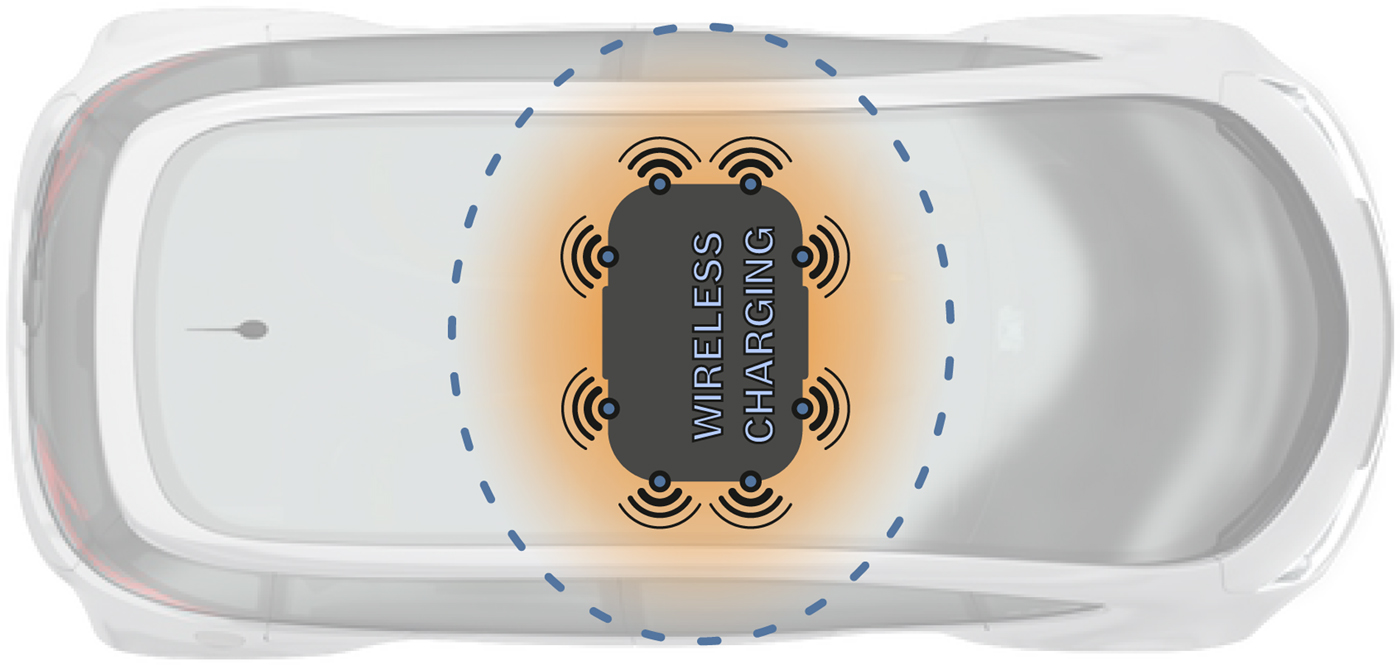
Several approaches exploit that the base pad containing the primary coil can be equipped with additional sensors easily. Unfortunately, most approaches only detect foreign objects when they have already entered the protection area, or they are not robust enough against external environmental factors like wetness or foliage. That is why only the most promising approach with infrastructure side sensors for LOP is described at this point. An exemplary sensor arrangement illustrated in Fig. 2 utilizes eight transceivers in total to detect foreign objects in the vicinity of the primary coil.
Inductive charging pad containing the primary coil and an exemplary sensor arrangement to detect foreign objects entering the protection area (blue, dashed) below an EV.
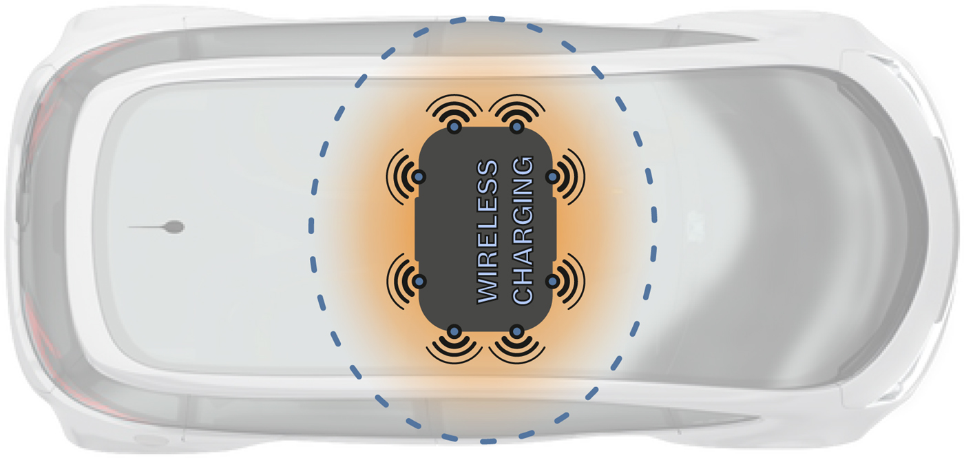
If the sensor concept is implemented with ultrasonic or radar technology, each of the transceivers is capable of detecting objects that enter the protection area and delivers its measured distance to the base pad. This information enables the system to stop the charging process if the protection area is entered by a foreign object. Furthermore, the protection area size can be varied by considering the measured distances. This approach has been implemented by Qualcomm in its Halo charging system with ultra-wideband radar sensors, which are often used for near field applications, since they are capable of measuring object distances robustly in the near field of the sensor [Reference Pluta16, Reference Mallinson17].
C) Air gap monitoring with sensors on the vehicle side
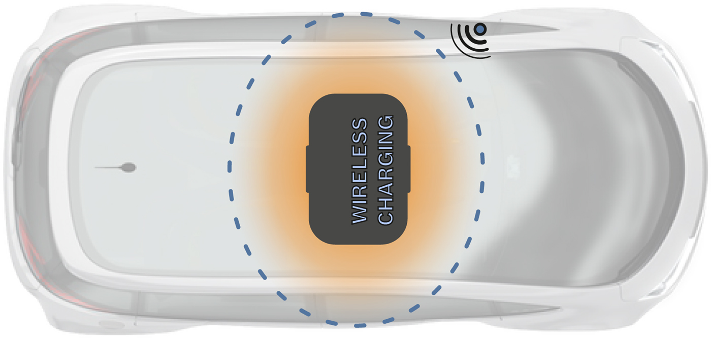
In this subsection, we propose a new approach exploiting that the vehicle size is larger than the protection area. Hence, the vehicle underbody can be equipped with only a few sensors capable of monitoring the whole protection area. Figure 3 depicts an exemplary implementation, where only one sensor is attached to the vehicle edge, and oriented toward the protection area. For this approach, it is reasonable to use high-frequency radar sensors similar to the ones that are already used in the automotive industry. Furthermore, they can be mounted at the vehicle just like the radar sensors for advanced driver assistance systems (ADAS). With a suitable antenna design, the field of view can be designed such that the whole protection area can be covered by using only one radar sensor. Additionally, the usage of multiple transmit and receive antennas enables an estimation of the angle-of-arrival (AoA), which can be used for a two-dimensional localization of foreign objects under the vehicle. In addition, multilateration techniques can be applied when attaching a second radar sensor to the opposite edge of the vehicle.
Inductive charging pad containing the primary coil below an EV that is equipped with a sensor at its underbody to monitor the whole protection area (blue, dashed).
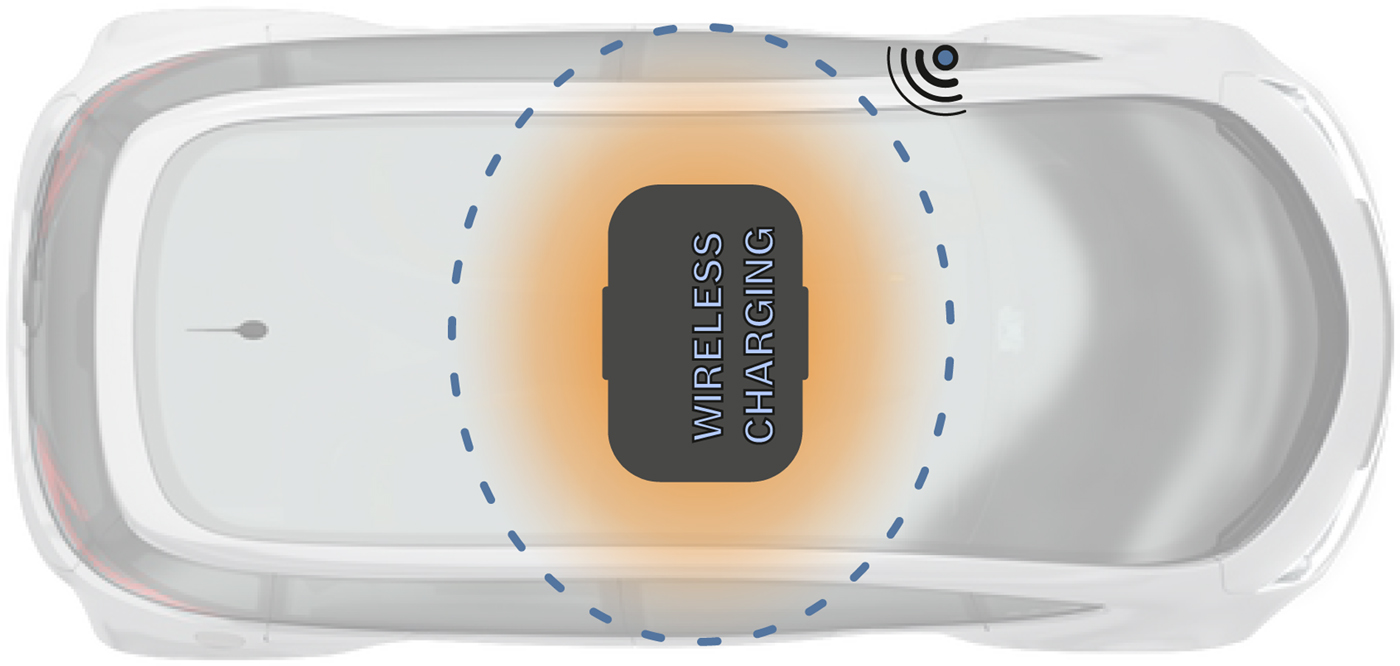
While the integration of additional sensors on the vehicle side is often considered as undesirable, this approach provides several advantages compared with the integration of infrastructure side sensors. First of all, the whole protection area, including the most hazardous zone directly between the coils, can be monitored using only one or two radar sensors. Since the reference levels for the alternating magnetic field are always met outside of the protection area, influences of the inductive charging system are also excluded. When taking into consideration that primary coils are intended to be embedded into the parking space ground, the vehicle side integration is favorable due to its independence from ground conditions. Furthermore, air gap monitoring could become relevant in the context of automated driving, which makes the concept multiply deployable.
III. PROTOTYPICAL IMPLEMENTATION
Since the standardization activities relating to inductive charging systems are still in progress, its installation point is not stipulated yet. As it is illustrated in Fig. 3, the coils are assumed to be mounted in the vehicle center. No matter where the coils will be located, the basic requirements and challenges of putting the vehicle side radar sensor into operation remain the same. This is why an automotive radar sensor has been attached to an idealized underbody for LOP evaluation regarding its feasibility. The following section describes this prototypical implementation, which is used for carrying out measurements with reproducible results.
A) Idealized vehicle underbody
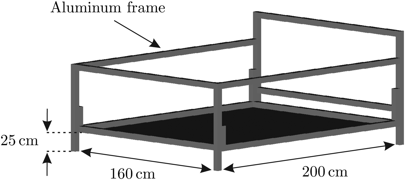
As underbody structures vary depending on the specific vehicle, an idealized underbody has been designed to be used for the prototypical implementation. Typically, EVs are equipped with lithium-ion battery packs, which are mounted between the passenger floor cabin panel and the driving surface. A ballistic shield made of aluminum or titanium [Reference Rawlinson18] protects the battery in case of an accident and reduces fire risks [Reference Ivory19]. This battery shielding causes EVs to have very flat underbodies compared with those of most vehicles with combustion engine. Hence, the vehicle underbody can be reproduced by a plane aluminum plate. Figure 4 illustrates the CAD model of the construction.
A CAD model of the idealized vehicle underbody realized with a plane aluminum plate of size
 $200 \times 160{\kern 1pt} \,{\rm cm}$
which is supported by a frame, which makes the construction portable.

It can be observed that the aluminum plate is supported by a frame, which makes the construction portable. The plate size is 200 × 160 cm2 and its height above ground is adjusted to 25 cm which could also be varied. Due to the planarity of the idealized vehicle underbody, specific reflection properties can be neglected in first place. These effects can be considered separately and evaluated subsequently by attaching further potentially influencing objects to the idealized underbody, like vehicle wheels or the charging coils.
B) Automotive radar sensor
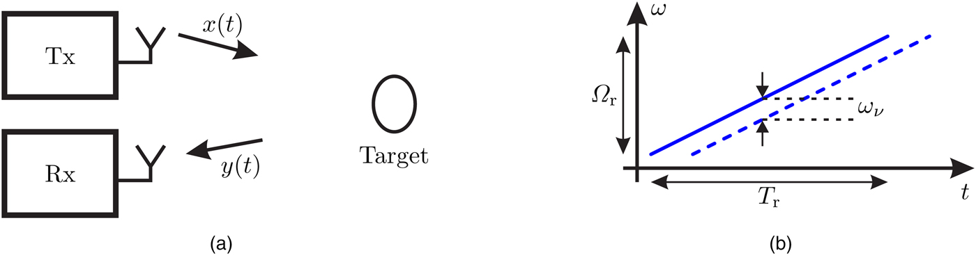
The measurements presented in this work have been carried out with a prototypical radar sensor similar to the ones used for ADAS. Hence, the sensor operates in the 77 GHz frequency band and uses the linear frequency continuous wave (FMCW) modulation with which the transmit signal of the radar system can be expressed mathematically as
 $$x(t) = \cos (\varphi (t)),\,\,{\rm with}\,\,\varphi (t) = \varphi _0 + \omega _0t + \displaystyle{{K_r} \over 2}t^2.$$
Equation (1) describes the chirp with its initial phase φ0, its start frequency ω 0, and the bandwidth-duration ratio K r . Figure 5(a) depicts the block diagram of a radar system and illustrates how radars work in principle. The received signal y(t) is delayed by the time of flight τ ν the signal takes to some target ν and back to the radar sensor. It is illustrated in Fig. 5(b) that this delay results in a frequency difference ω ν between the transmitted and the received chirp, which can be computed with the bandwidth-duration ratio as
 $$\omega _\nu = K_r\tau _\nu, \,\,{\rm with}\,\,K_r = \displaystyle{{\Omega _r} \over {T_r}} = \displaystyle{{2\pi B_r} \over {T_r}}$$
and where B r and T r denote bandwidth and duration of the chirp, respectively.
Principle of FMCW radar sensors. (a) Block diagram of a principal radar system with transmit and receive signals x(t) and y(t), respectively. (b) Frequency difference ω ν resulting from x(t) (solid) and y(t) (dashed).
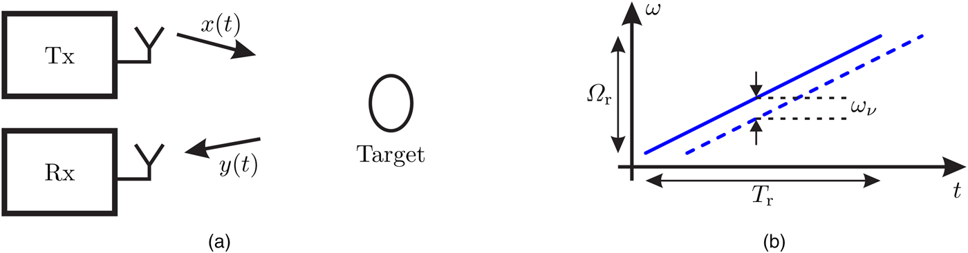
To extract the frequency difference, the signals x(t) and y(t) become multiplied followed by a low pass filter, resulting in a cosine with the difference frequency. For simplicity, the following calculations are conducted with the analytical signal, which can be obtained by applying a Hilbert transformation. Assuming a multiple target scenario with n reflections, a superposition of the beat signals corresponding to each target ν results in
 $$s(t) = \sum\limits_{\nu = 0}^{n - 1} A_\nu e^{j\omega _\nu t},$$
where the weights A ν indicate the reflection strength depending on the radar cross-section (RCS). The RCS is a measure of the targets’ detectability and it is dependent on its size, physical geometry, material, and the transmit frequency [Reference Skolnik20]. After analog processing of x(t) and y(t), sampling the resulting beat signal s(t) results in
 $$s_\kappa = s(t_\kappa ) = \sum\limits_{\nu = 0}^{n - 1} A_\nu e^{j\omega _\nu t_\kappa}, \,\,{\rm with}\;t_\kappa = \displaystyle{{\kappa T_r} \over n},\,\,{\rm for}\;0 \le \kappa \lt n.$$
The transmission channels’ behavior can be approximated by assuming the reflections’ difference in time of flight to be equidistant [Reference Poguntke and Ochs21]. By choosing the delay spacing between the reflections as
 $$\tau _\nu = \displaystyle{{2\pi \nu} \over {\Omega _r}}\quad \Leftrightarrow \quad \omega _\nu = \displaystyle{{2\pi \nu} \over {T_r}},$$
the resulting discrete beat signal s κ can be written with equations (4) and (5) as
 $$s_\kappa = \sum\limits_{\nu = 0}^{n - 1} A_\nu w_n^{ - \nu \kappa}, \,\,{\rm where}\;w_n = e^{ - j(2\pi /n)}$$
denotes a primitive nth root of unity. We want to use this notation, since the beat signal appears to be similar to the discrete Fourier transform (DFT) definition and w n is frequently used for the DFT matrix formulation. To determine the frequency components of the discrete beat signal, a DFT is applied and it results
 $$S_\lambda = DFT\left\{ {s_\kappa} \right\} = \sum\limits_{\nu = 0}^{n - 1} A_\nu \sum\limits_{\kappa = 0}^{n - 1} w_n^{ - \nu \kappa} w_n^{\lambda \kappa}. $$
Utilizing the finite geometric series or the Dirichlet kernel, the spectrum S λ can be calculated analytically [Reference Lyons22]. Typically, only the absolute value of the spectrum is evaluated. This is why the phase shifts arising due to the fact that the DFT is not centered can be neglected. Thus, the absolute value of the spectrum can be written as
 $$ \vert S_\lambda \vert = \left \vert {\sum\limits_{\nu = 0}^{n - 1} A_\nu \displaystyle{{\sin (\pi (\nu - \lambda ))} \over {\sin (\pi (\nu - \lambda )/n)}}} \right \vert. $$
As usual, the spectrum of a discrete signal is periodic and one period contains all the relevant information. This property can be exploited by considering only one period of the spectrum. Using the Kronecker product
 $$\delta _{\nu, \lambda} = \left \{ {\matrix{ 1 & {{\rm for}\;\nu = \lambda,} \cr 0 & {{\rm else,}} \cr}} \right.$$
the spectrum formulation can be simplified and it results
 $$ \vert S_\lambda \vert = \left \vert {\sum\limits_{\nu = 0}^{n - 1} A_\nu \delta _{\nu, \lambda}} \right \vert = \sum\limits_{\nu = 0}^{n - 1} \vert A_\nu \vert \delta _{\nu, \lambda}, \,\,{\rm for}\;0 \le \lambda \lt n.$$
It can be observed in equation (10) that each sample |S λ | corresponding to a frequency component equates to the weight |A λ |. Thus, we receive information about the reflection strengths and the corresponding signal times of flight. Considering the speed of light, the reflectors’ distances can be computed.
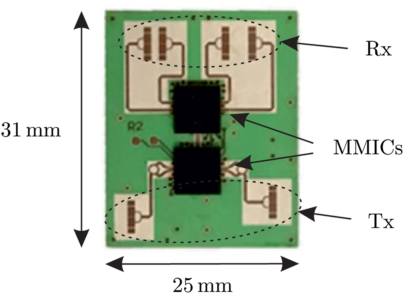
Figure 6 depicts the RF front-end of the prototypical radar sensor. The Monolithic Microwave Integrated Circuits are also used for the fourth-generation Bosch Mid Range Radar and their technology is described in [Reference Hasch, Topak, Schnabel, Zwick, Weigel and Waldschmidt23]. As it is illustrated, the radar sensor is equipped with four receive and two transmit antennas, allowing measurements of distance, velocity, and an estimation of the AoA in principle.
The RF front-end of the prototypical radar sensor.
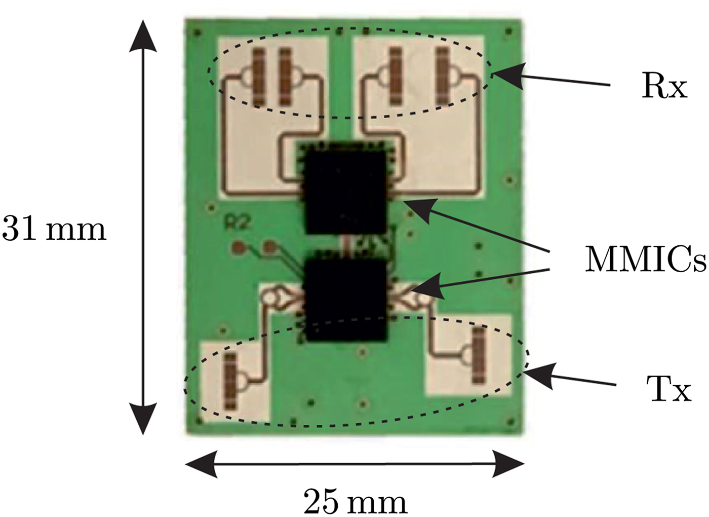
However, the angle information is not used in this paper. That is why the signal is only transmitted by one of the transmit antennas, while the signals received by each of the receive antennas are processed with non-coherent integration. Consequently, the spectrum results in
 $$S_\lambda ^{nci} = \vert S_\lambda ^{nci} \vert = \displaystyle{1 \over 4}\sum\limits_{\nu = 1}^4 \vert S_\lambda ^\nu \vert. $$
With a field of view of 120° and 60° in azimuth and elevation, respectively, the sensor is not optimally designed for the application of air gap monitoring. Since wider elevation angles increase the multipath propagation due to the narrow air gap, a smaller elevation angle would be preferable. However, the radar sensor is suitable for a feasibility analysis of LOP using the prototypical system implementation.
IV. MEASUREMENTS FOR AIR GAP MONITORING
While metal objects can be detected by the presented radar sensor, they have typically a very small RCS for relevant use cases of systems for foreign object detection, especially if there is a small coin or a screw laying on the ground. In equation (10), this leads to small weights A ν , which makes a successful detection very unlikely. That is why the proposed system is not suitable to be used for the detection of metal objects. This section provides measurement results only for relevant use cases of LOP systems. Therefore, the proposed system concept using one radar sensor on the vehicle side has been realized using the prototypical implementation described in the previous section. After illustrating the sensor arrangement in the first subsection, we implemented signal processing algorithms in MATLAB for peak detection and for removing static reflections of the idealized vehicle underbody. Applying these algorithms, a field of view has been recorded for the automotive radar sensor attached to the vehicle edge. This field of view delivers important insights into where foreign objects inside the protection area can be detected. Finally, this section describes and utilizes two-dimensional signal processing techniques for the detection of moving objects inside the air gap by considering the Doppler effect. Measurement results will be presented for specific use cases widely discussed in the community of inductive charging.
A) Sensor arrangement
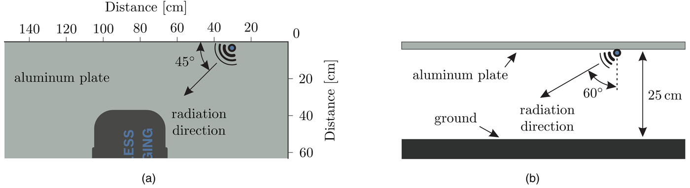
The sensor on the vehicle side must be attached properly to the idealized underbody to ensure that the protection area can be covered by using only one sensor and to prevent a strengthened multipath propagation. This is the reason why both vertical and horizontal orientation of the sensor have to be taken into consideration. While the sensor is arranged as it is illustrated in Fig. 3, the attachment of the sensor is drawn in Fig. 7.
Measurement scenario with a radar sensor attached to the idealized underbody. (a) Top view: the sensor is turned about 45° and it is heading toward the base pad, which is not respected for measurements. (b) Side view: the sensor with aperture angle of 60° is bended away from the aluminum plate.
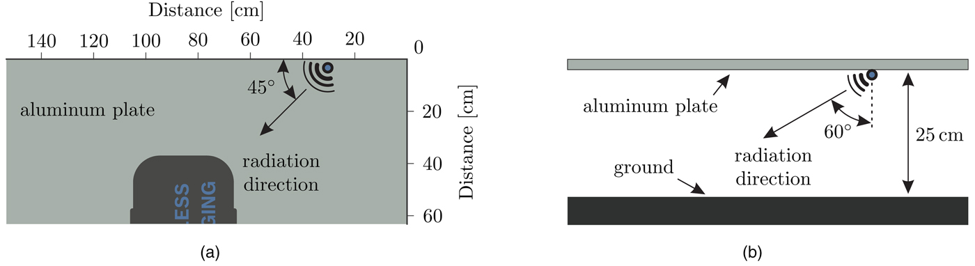
Figure 7(a) depicts the top view of the measurement scenario. It can be observed that the radar sensor is attached 30 cm apart from the plate corner at its long edge. With an aperture angle of 120° in horizontal direction, the protection area can be covered completely when turning the sensor about 45° toward the most hazardous zone right between the coils. With an aperture angle of 60° in vertical direction, it is illustrated in Fig. 7(b) that the sensor is bent away from the aluminum plate about 60° for reducing multipath propagation, which arises from both the ground and the aluminum plate.
B) Object detection with background subtraction
While a perfect differentiation between living and non-living objects is not possible with radar sensors, the aim is to implement a reliable sensing solution using robust signal processing algorithms. This prevents unintended charging switch-offs caused by false alarms of the LOP system. Contrary to non-living objects, it is assumed that living objects always move, even if it is just the respiration or other slight shaking movements. This characteristic can be used for distinguishing moving objects from the reflections evoked by the static background scenario, e.g. the vehicle underbody. There exist several algorithms for the detection of moving objects within a static scenario by neglecting the time-invariant background, e.g. exponential filtering [Reference Zetík, Sachs and Peyerl24]. In this paper, we utilize a conventional background subtraction for neglecting the reflections evoked by the static scenario.
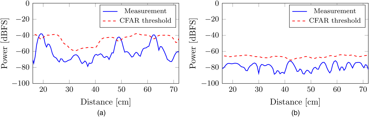
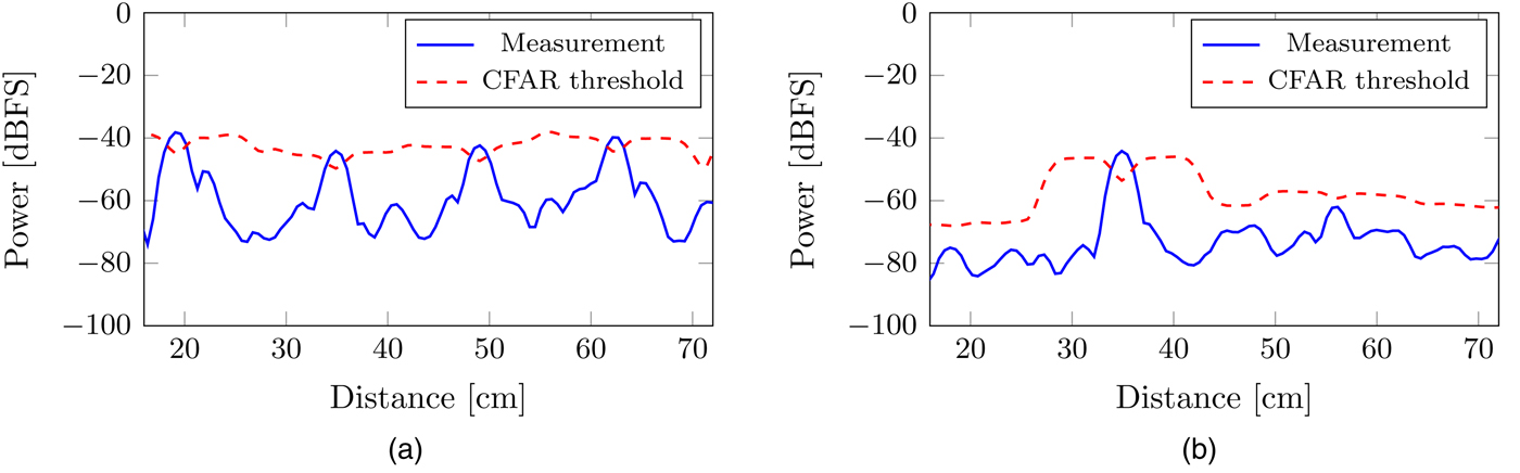
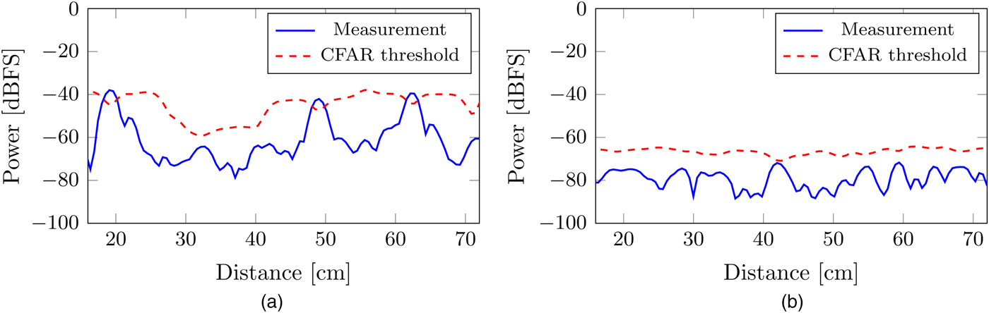
In order to illustrate the influence of background subtraction, two subsequent measurements of a static scenario have been carried out. One of the measurements is illustrated in Fig. 8(a), where the spectrum
 $\vert S_\lambda ^{{\rm nci}} \vert $
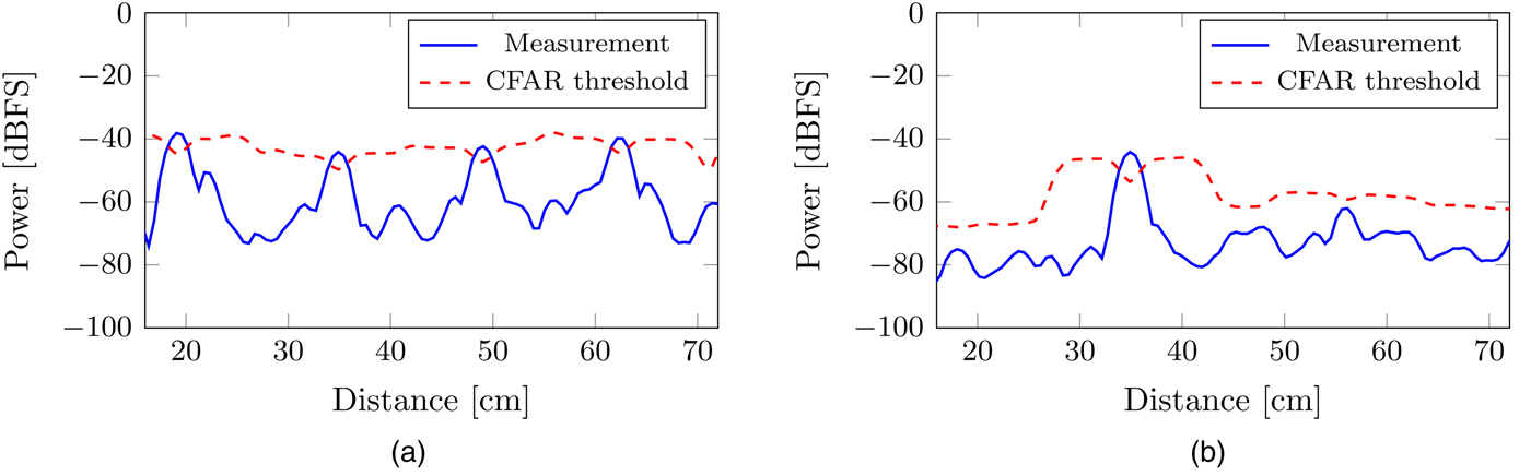
and a constant false alarm rate (CFAR) threshold for peak detection are plotted. For this paper, a cell averaging (CA-CFAR) threshold is used [Reference Rohling25]. The static scenario evokes three detectable peaks, which would cause an unintended system switch-off. The adjusted measurement data with background subtraction is illustrated in Fig. 8(b). It can be observed that the static scenario does not produce unintended peak detections anymore since the static background is subtracted. Figure 9 illustrates the influences of background subtraction, if an object enters the static scenario while another measurement is performed. The raw measurement data in Fig. 9(a) correspond to the raw data plotted in Fig. 8(b) complemented with a new object at a distance of approximately 35 cm. It can be observed that the peaks cannot be differentiated. In contrast, the adjusted measurement data in Fig. 9(b) shows one major peak that corresponds to the added object above the CFAR threshold. Thus, the peak of an object in a static scenario can be detected using a conventional peak detection.
Background subtraction in case of three non-moving objects recorded as a static scenario with spectrum
 $\vert S_\lambda ^{nci} \vert $
of the measurement (blue, solid) and CFAR threshold (red, dashed). (a) Three peaks detected without further processing. (b) No detection after elimination of background.
Background subtraction in case of one object added to the static scenario recorded in Fig. 8 with spectrum
 $\vert S_\lambda ^{nci} \vert $
of the measurement (blue, solid) and CFAR threshold (red, dashed). (a) Four objects detected without further processing. (b) Object detection after elimination of background.
C) Field of view of the radar sensor
In this section, we present measurements resulting in the sensor's field of view. This is important for the evaluation of air gap monitoring using one radar sensor on the vehicle side regarding to its feasibility. As a transmit signal, a chirp with parametrization
 $$B_r \approx 3931{\kern 1pt} {\rm MHz},\;T_r \approx 3.3{\kern 1pt} {\rm ms},\,\,{\rm and}\,\,n = 256$$
is used. The measurements have been carried out while a reference object is placed along a raster of 20 × 20 cm. So, there is one measurement for each position on the
 $160 \times 180{\kern 1pt} {\kern 1pt} {\rm cm}$
raster, each adjusted by applying the background subtraction. Before measuring each row in the raster, the measurement data of the static background is updated.
The reference object for the following measurements is a water balloon filled with 1 l of water, which corresponds to a sphere of 12.41 cm in diameter. Since the water balloon is a good reflector, as well as symmetrical, it represents a suitable reference object that also resembles a child's head with respect to reflection characteristics. Thus, the measurements also correspond to a practical use case for LOP systems, which is discussed in the community of inductive charging.
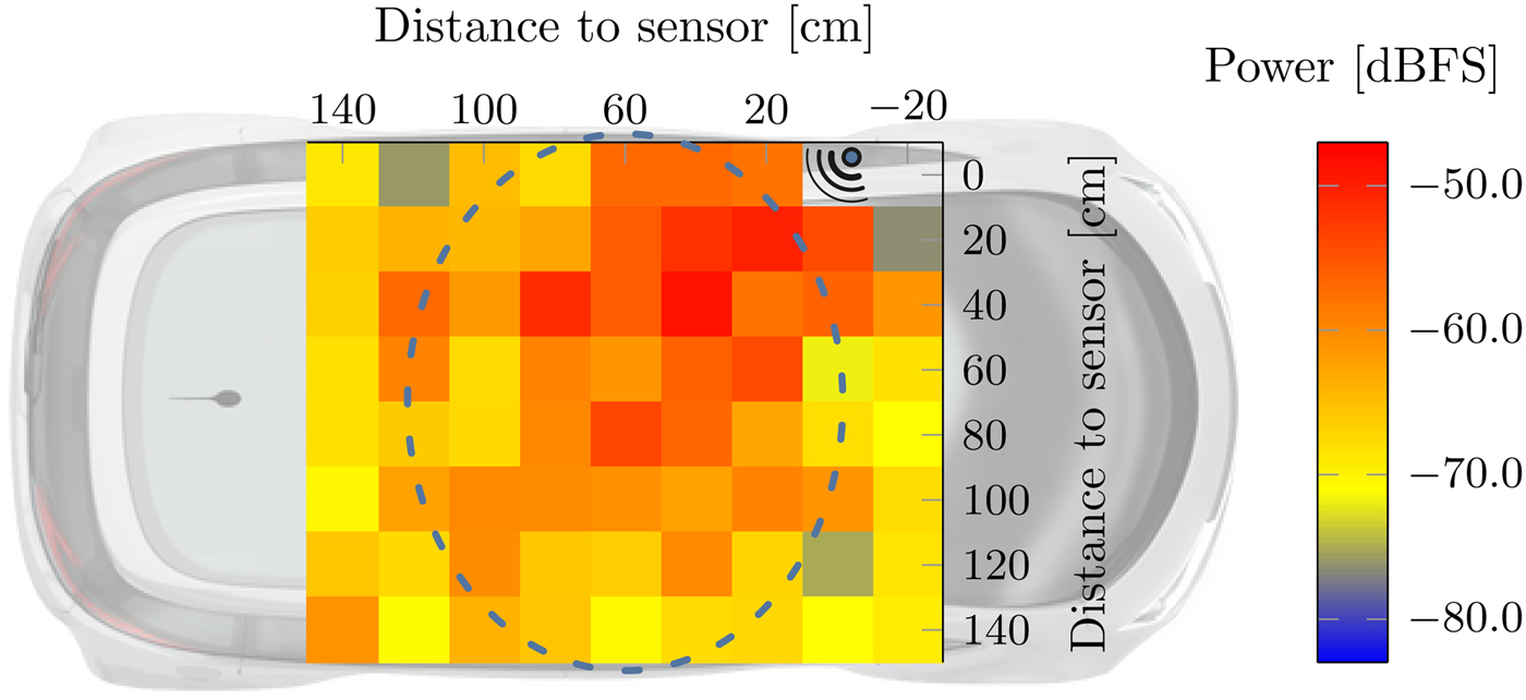
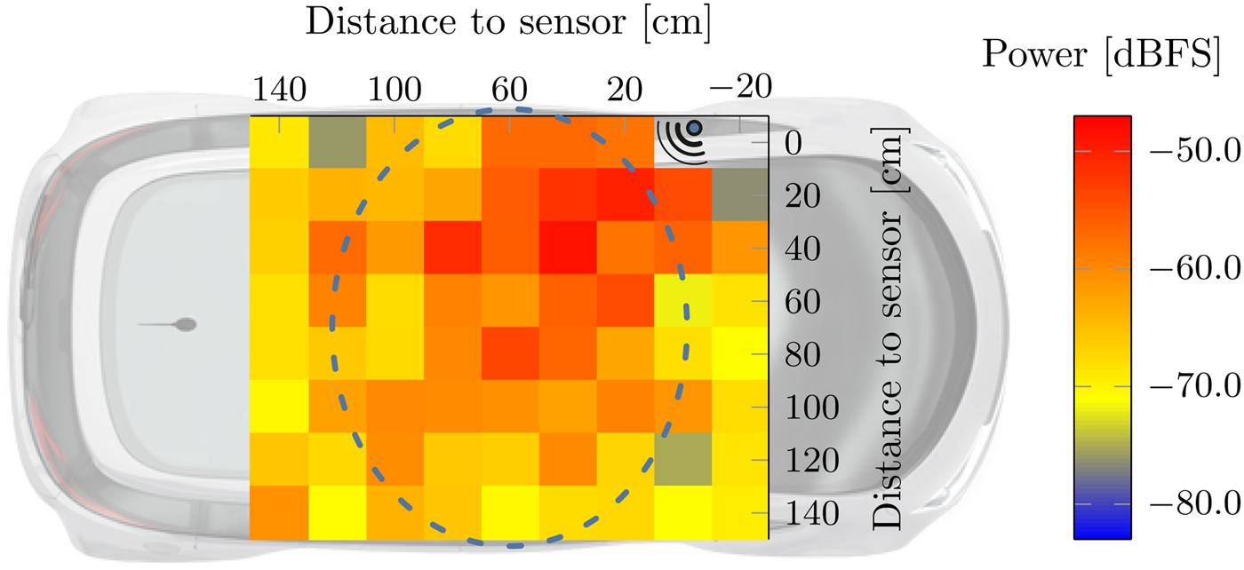
The peak detection is performed by a CA-CFAR threshold, just as it is illustrated in Fig. 9(b). If the distance of a detected peak matches the geometrical distance of the object, its amplitude is recorded together with the corresponding raster position. A two-dimensional depiction of where the reference object can be detected results from repeating this step for each position on the raster. Figure 10 illustrates the field of view where the color indicates the peak's amplitude. The reference object has been detected at every position of the raster, except for two positions where the water balloon was placed behind or directly beneath the sensor. Since the peak amplitudes decrease when the reference object has been moved away from the sensor or out of the main radiation direction, the measurements are very comprehensible and produce the expected results. It can be observed that the reference object has been detected in the whole protection area under the idealized vehicle so that the charging system can be switched off as soon as a foreign object enters that area. Thus, the recorded field of view indicates that air gap monitoring using one radar sensor on the vehicle side is principally feasible.
Two-dimensional field of view recorded under the idealized underbody, where the reference object has been detected at every colored point and the color indicates the peak strength.
D) Detection of moving foreign objects
When an electromagnetic wave gets reflected from a moving object, its frequency gets shifted. This is known as the Doppler effect, where the object's velocity can be computed from that frequency shift. Fortunately, there are radar modulation techniques available that can determine the moving object's range and velocity simultaneously. In this section, a radar modulation technique referred to as chirp sequence modulation is used [Reference Poguntke and Ochs21, Reference Schubert, Meinl, Kunert and Menzel26, Reference Andres, Menzel, Bloecher and Dickmann27], where 64 chirps are transmitted in one chirp sequence and each chirp is parametrized with
 $$B_r \approx 1375{\kern 1pt} {\rm MHz},\;T_r = 0.36{\kern 1pt} {\rm ms},\;{\rm and}\;n = 152.$$
Since living objects always move and therefore evoke a frequency shift, all static reflections without a frequency shift can be eliminated by applying a continuous background subtraction. By subtracting every two subsequent measurements from each other, only objects evoking a Doppler shift become detectable in the adjusted measurement data.
1) Moving objects inside of the air gap
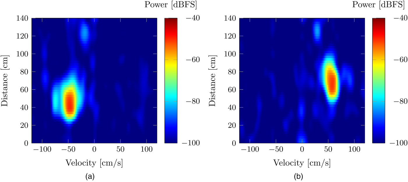
In contrast to the measurements carried out for the field of view, the non-moving water balloon would have been neglected immediately when applying the continuous background subtraction. The chirp sequence modulation has been used for the detection of moving objects, and a continuous background subtraction is applied for each sequence of chirps. The resulting so-called Range-Doppler spectrum for measurements of the water balloon rolling under the idealized underbody is illustrated in Fig. 11. On the left-hand side, a measurement can be observed where the reference object is moving toward the sensor. At time of measurement, the object is 50 cm away from the sensor and evokes a negative Doppler frequency. On the right-hand side, the reference object is moving away from the sensor, and thus, it evokes a positive Doppler frequency. Both figures illustrate that static reflections caused by the time-invariant scenario are eliminated efficiently since there are no peaks visible on the axis with zero Doppler frequency.
Range-Doppler spectra showing that a water balloon moving under the vehicle can be detected using two-dimensional signal processing and continuous background subtraction. (a) Reference object rolling toward the sensor. (b) Reference object rolling away from the sensor.
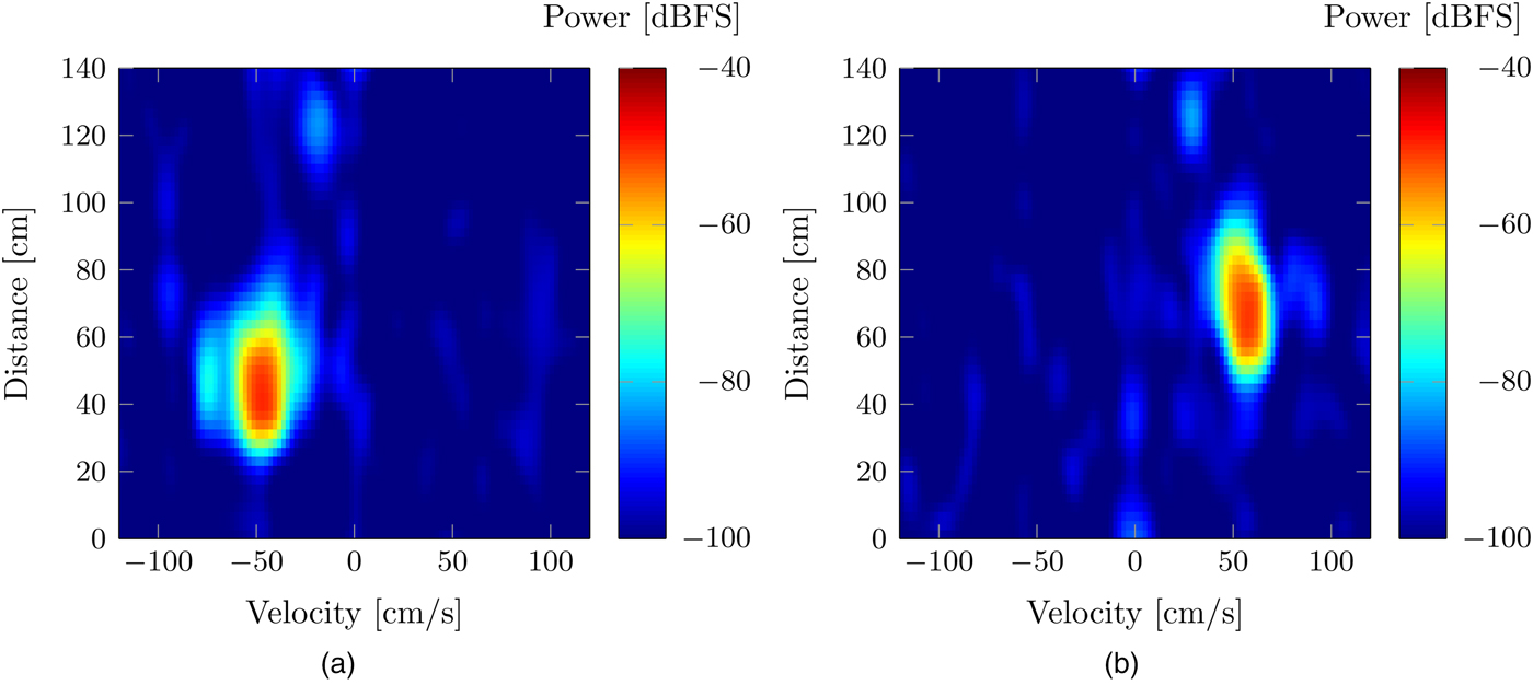
The presented measurements motivate the use of two-dimensional signal processing to evaluate the object's range as well as the Doppler frequency evoked by its movement simultaneously, since irrelevant reflections can be eliminated efficiently. The application under a vehicle, where a lot of static reflections are provoked, makes a continuous background subtraction especially attractive and suitable for LOP systems.
2) Outstretched arm under the vehicle
A widely discussed use case in the community of inductive charging describes a human arm that is outstretched under the vehicle to pick up car keys that may have dropped. This use case can be simulated easily by carrying out measurements of an arm that is outstretched under the idealized vehicle underbody. The arm is stretched out under the long edge of the underbody, which corresponds to the drivers’ side in the setup illustration in Fig. 3. It is placed approximately 40 cm apart from the sensor and thus oriented directly toward the base pad.
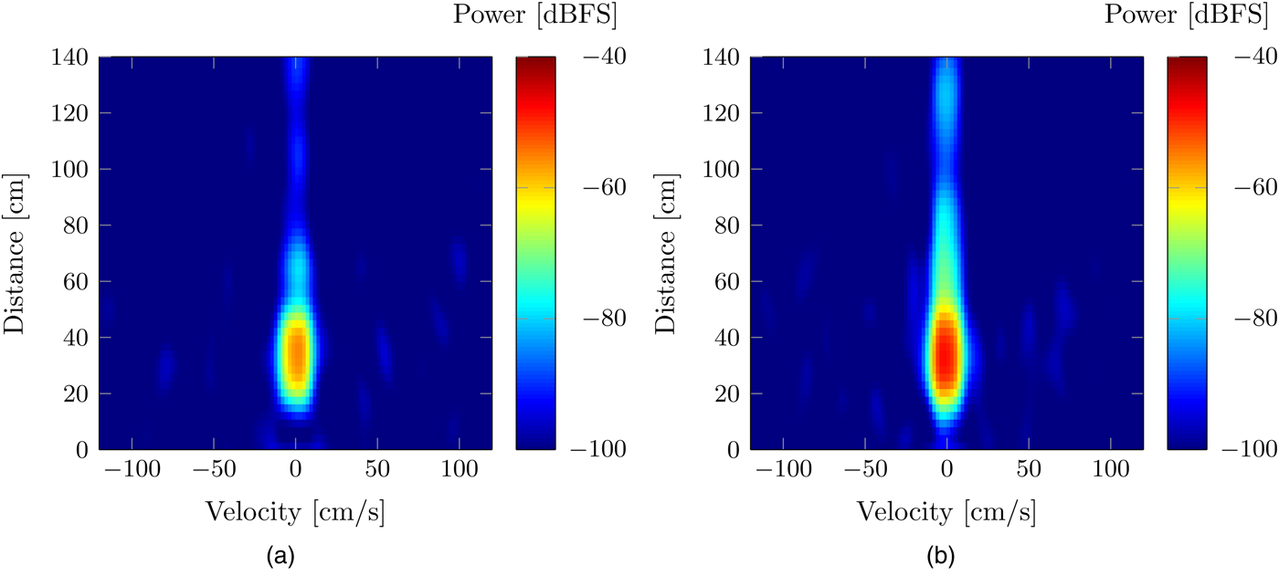
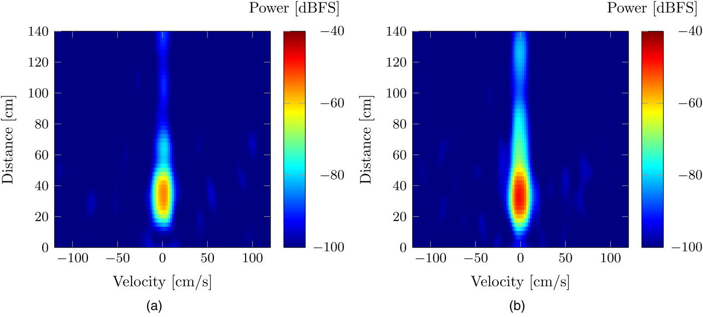
The measurement results, after applying the continuous background subtraction, are depicted in Fig. 12. Both measurements show a dominant peak near the zero Doppler frequency axis, while a difference can be found in the peak amplitude. As a half forearm under the vehicle evokes stronger reflections compared with only a hand outstretched under the vehicle, the presented measurements show the expected results. However, the important aspect is that both gestures have been successfully detected. It is also worth noting that the test person tried to keep their arm still. Thus, the frequency shift provoked by the slight unintentional arm shaking suffices for being detected when applying the continuous background subtraction. That being said, a human would not intentionally hold an arm still but move it in a real application scenario.
Range-Doppler spectra showing that an outstretched arm under the vehicle can be detected using two-dimensional signal processing and continuous background subtraction. (a) Outstretched hand under the vehicle. (b) Half outstretched forearm under the vehicle.
V. CONCLUSION
In this paper, we introduced a new approach to prevent living objects from being exposed to an alternating magnetic field evoked by inductive charging systems. A prototypical implementation is presented consisting of an automotive radar sensor attached to an idealized vehicle underbody. We have proven that a protection area of
 $150{\kern 1pt} {\rm cm} \times 150{\kern 1pt} {\rm cm}$
can be covered by using only one radar sensor on the vehicle side. To meet the requirements of inductive charging systems, two-dimensional signal processing techniques are applied to detect even the slightest movements of foreign objects. This enables a sensitive differentiation between moving and non-moving objects for preventing unintended system switch-offs due to false alarms. In particular, the presented measurements show that a calmly held hand under the vehicle can be detected and differentiated from the reflections of static objects. Since this represents a challenging use case for LOP systems, our results give evidence that the proposed approach for air gap monitoring using one radar sensor on the vehicle side is principally feasible.
The promising results motivate further investigations on the usability of this new approach, including the robustness in case of pedestrians walking besides the vehicle and an AoA estimation to determine the foreign object's position in a two-dimensional coordinate system.
ACKNOWLEDGEMENTS
This work was supported by the German Federal Ministry for Economic Affairs and Energy via the public funded project “BiLawE” [28].
STATEMENT OF INTEREST
None.
 Tim Poguntke was born in Überlingen, Germany, in 1989. He received a B.Sc. and a M.Sc. degree in Electrical Engineering and Information Technology from Ruhr-Universität Bochum, Germany, in 2012 and 2014, respectively. Currently, he is a Ph.D. student at Corporate Sector Research and Advance Engineering of Robert Bosch GmbH, Renningen, Germany. His research interests include time-variant system theory, digital signal processing, and radar technology.
 Philipp Schumann was born in Kronberg, Germany, in 1975. He received his Diploma in Physics and his Ph.D. in Natural Sciences in 2001 and 2006, respectively, both from the University of Mainz, Mainz, Germany. From 2005 to 2012, he served as a firmware developer and group manager at FARO Scanner Production GmbH, Korntal-Münchingen, Germany. Currently, he is senior manager in the field of “Charging Systems and Infrastructure” within the Corporate Sector Research and Advance Engineering of Robert Bosch GmbH, Renningen, Germany.
 Karlheinz Ochs was born in Lingen, Germany, in 1968. He received the Dipl.-Ing. degree and the Dr.-Ing. degree in Electrical Engineering in 1996 and 2001, respectively, both from the University of Paderborn, Paderborn, Germany. From 2001 to 2002, he was a Design Engineer in the Technology and Development Center, Siemens AG, Bruchsal, Germany. Currently, he is an Associate Professor in the Department of Electrical Engineering and Information Technology at the Ruhr-Universität Bochum, Bochum, Germany. His research interests include modeling, simulation, and emulation of physical systems and neuromorphic circuits.