1. Introduction
Radio-frequency (RF) wave scattering in inhomogeneous magnetized plasmas has recently attracted much attention, in particular as a mechanism of RF power redirection at the periphery of magnetic fusion devices. Myra & D'Ippolito (Reference Myra and D'Ippolito2010), Ram & Hizanidis (Reference Ram and Hizanidis2016), Lau et al. (Reference Lau, Martin, Bertelli, Shiraiwa, Tierens, Brookman, Pinsker, Van Compernolle, Ram, Wallace, Dimits, Myra, Vincena and Yang2020), Tierens et al. (Reference Tierens, Zhang and Myra2020a,Reference Tierens, Zhang and Manzb, Reference Tierens, Bilato, Bertelli, Shiraiwa, Myra and Colas2022a,Reference Tierens, Myra, Bilato and Colasb), Biswas et al. (Reference Biswas, Shiraiwa, Baek, Bonoli, Ram and White2021) and Zhang et al. (Reference Zhang, Tierens, Bobkov, Cathey, Cziegler, Griener, Hoelzl and Cardaun2021) provide an overview of recent modelling work on this topic in the lower hybrid and ion cyclotron ranges of frequencies (ICRF). Scattering of fast magnetosonic waves, without change of polarization, is generally modest in the ICRF range, because the typical size of inhomogeneities transverse to the magnetic field does not match the typical transverse wavelength of the fast wave (Myra & D'Ippolito Reference Myra and D'Ippolito2010). Tierens et al. (Reference Tierens, Zhang and Myra2020a,Reference Tierens, Zhang and Manzb, Reference Tierens, Bilato, Bertelli, Shiraiwa, Myra and Colas2022a,Reference Tierens, Myra, Bilato and Colasb) proposed a more efficient process: evanescent filament assisted mode conversion (FAMC) modes produced by the nearly resonant scattering of High Harmonic Fast Waves (HHFW) off cylindrical field-aligned density inhomogeneities (likely turbulent ‘filaments’). The FAMC modes are similar to surface plasmons propagating along planar or patterned dielectric/metal interfaces (Raether Reference Raether1988; Garcia-Vidal et al. Reference Garcia-Vidal, Fernandez-Domingez, Martin-Moreno, Zhang, Tang, Peng and Cui2022) or near the boundaries of plasma-filled waveguides (Girka & Thumm Reference Girka and Thumm2022). One can see the FAMC modes as a generalization of plasmons to cylindrical interfaces in magnetized plasmas, allowing for curvature effects and mode mixing in the HHFW regime. The FAMC modes belong to a broader zoology of ICRF surface waves (Myra & D'Ippolito Reference Myra and D'Ippolito2010; Tierens et al. Reference Tierens, Zhang and Myra2020a). Using a spectral approach in the parallel direction, Tierens et al. (Reference Tierens, Bilato, Bertelli, Shiraiwa, Myra and Colas2022a) estimated analytically their dispersion relation, as well as the fraction of the launched HHFW power that they could parasitically divert from the core plasma. Tierens et al. (Reference Tierens, Bilato, Bertelli, Shiraiwa, Myra and Colas2022a) evidenced finite RF power damping in the filament volume even in the limit of vanishing anti-Hermitian part of the dielectric tensor. Statistics of this power redirection, over a population of turbulent filaments observed on the National Spherical Torus eXperiment (NSTX) in Princeton, could reproduce several experimental trends about the missing HHFW power in the core of this device (Tierens et al. Reference Tierens, Myra, Bilato and Colas2022b).
The previous Fourier treatment implicitly assumed straight magnetic field lines with infinite parallel extent. One, however, suspects the resonant scattering to occur in the Scrape-Off Layer (SOL) of magnetic fusion devices, where magnetic field lines have a large but finite parallel extent. Experiments on NSTX suggest spurious interactions at the extremities of specific magnetic field lines passing near the HHFW launchers (Perkins et al. Reference Perkins, Hosea, Jaworski, Ahn, Diallo, Bell, Bertelli, Gerhardt, Gray, Krammer, LeBlanc, McLean, Phillips, Podesta, Roquemore, Saggagh, Taylor and Wilson2015, Reference Perkins, Hosea, Jaworski, Bell, Bertelli, Kramer, Roquemore, Taylor and Wilson2017). Although these extremities are located far away toroidally from the HHFW antenna, they could also play a role in the power dissipation, but the previous models did not consider them explicitly. Within a simplified analytic approach, the present paper explores how the nearly resonant FAMC modes can possibly excite sheath RF oscillations at the extremities of bounded filaments in the SOL of a tokamak. In the limit of vanishing collisionality, finite collisional damping is only possible if the nearly resonant mode can extend indefinitely in the parallel direction (Tierens et al. Reference Tierens, Bilato, Bertelli, Shiraiwa, Myra and Colas2022a). As the filaments guide the nearly resonant FAMC modes with weak parallel damping, the RF sheath excitation can be efficient even at large parallel distances from the HHFW launcher, and the sheath dissipation can possibly dominate the losses over the volume damping.
This document is organized as follows. Section 2 recalls the nearly resonant FAMC modes on infinite magnetic field lines, as studied in the spectral domain in Tierens et al. (Reference Tierens, Zhang and Myra2020a, Reference Tierens, Bilato, Bertelli, Shiraiwa, Myra and Colas2022a). For practical use, we re-express the earlier results in the spatial domain, and thereby estimate the typical parallel extent of the FAMC modes in unbounded geometry, in the presence of weak dissipation in the plasma volume. We also compare the spatial structures of FAMC modes with opposite resonant parallel wave vectors. In analogy with Myra & Kohno (Reference Myra and Kohno2019) for plane waves, § 3 investigates analytically the partial reflection and dissipation of one FAMC mode at one isolated field line extremity, within simplifying assumptions concerning the sheaths. These simplified processes involve the FAMC mode with the opposite parallel wave vector. Using the results of this intermediate step, § 4 investigates the multi-reflections and multi-pass power dissipation of two interacting FAMC modes with opposite resonant parallel wave vectors, in the presence of volume losses and two sheaths at both ends of a bounded magnetic field line. Throughout the text we investigate how the presence of field line boundaries affects the HHFW power fraction redirected into the filament, and its splitting between sheath and volume losses, as a function of relevant parameters of the model. For that purpose, a technical appendix reformulates the Poynting theorem for electrostatic cylindrical filament modes. Section 5 discusses our simplifying assumptions and possible ways towards more realistic modelling.
2. Wave scattering by field-aligned cylindrical density inhomogeneity on infinite magnetic field lines: from spectral to spatial description
Throughout this document we consider a cold magnetized plasma extending over an infinite spatial domain in the (x,y) directions. The homogeneous background magnetic field B 0 is oriented along the z direction. In § 2 this parallel domain is also assumed infinite. The propagation of monochromatic waves oscillating as ${\rm exp} ( - \textrm{i}{\omega _0}t)$ with pulsation ω 0 is governed by the Helmholtz equation for the electromagnetic field E

where k 0 = ω 0/c is a wave vector in vacuum, c is the velocity of light in vacuum and ε is a cold plasma (normalized) dielectric tensor of the form

We assume that the dielectric tensor is independent of z and t. It exhibits a field-aligned density inhomogeneity. In cylindrical geometry (r,θ,z) we idealize the inhomogeneity as

In the SOL of tokamaks such inhomogeneity can possibly arise from filamentary turbulent structures, that are considered here as time independent on the typical scale of a RF wave period. Cold dielectric tensor element values are used (Stix Reference Stix1992), with one ion species, in the presence of a phenomenological friction with frequency ν. This way we introduce dissipation to induce RF power losses in the plasma volume, thereby regularizing the resonant scattering processes. We will call ‘nearly resonant’ the results obtained in the limit $\nu \to {0^ + }$ . In the HHFW regime, one approximates the tensor elements as


Here, we have introduced the following notations, consistent with (Tierens et al. Reference Tierens, Bilato, Bertelli, Shiraiwa, Myra and Colas2022a):
• ω pib is the plasma pulsation for the ions in the background plasma.
• ${\nu ^\ast } = \nu /{\omega _0}$
 is a non-dimensional phenomenological friction parameter, assumed positive and ‘small’ throughout the text. We will precise below several meanings of ‘small’, associated with ‘weak mode dissipation’ or ‘short magnetic field lines’.
• $R = {n_f}/{n_b}$
.• $\varphi = {\omega _0}/{\varOmega _{\textrm{ci}}}$
, where $\varOmega$ci is the ion cyclotron pulsation.• Mi/me is the ratio of ion to electron mass in the plasma.


In our model, an antenna launches a prescribed HHFW with fast wave polarization that impinges onto the cylindrical inhomogeneity. We examine how the filament scatters the incident wave, and the behaviour of the scattered RF fields near resonant conditions.
2.1. Wave scattering by filaments in the spectral domain
In an infinite spatial domain with vanishing scattered fields at infinity transverse to B 0, one can most easily solve the scattering problem in the spectral domain, by splitting the incident and scattered waves into independent cylindrical modes oscillating as ${\rm exp} (\textrm{i}m\theta + \textrm{i}{k_{/{/}}}z)$ . This subsection briefly summarizes this method used Ram & Hizanidis (Reference Ram and Hizanidis2016) and Tierens et al. (Reference Tierens, Zhang and Myra2020a, Reference Tierens, Bilato, Bertelli, Shiraiwa, Myra and Colas2022a). Tierens et al. (Reference Tierens, Zhang and Manz2020b) investigated numerically non-cylindrical FAMC modes in more realistic geometries and with more realistic density distributions. The RF fields inside and outside the filament are the superposition of cylindrical wave modes with slow and fast wave polarizations, of the form

Here, Im and Km are modified Bessel functions, where we have assumed evanescent modes both inside and outside the filament. The perpendicular wave vectors k ⊥b and k ⊥f are eigenvalues of the dispersion relation outside and inside the filaments, for prescribed k //

The field polarizations ${\hat{\boldsymbol{E}}_{\boldsymbol{b}}}(m,{k_\parallel })$ and ${\hat{\boldsymbol{E}}_{\boldsymbol{f}}}(m,{k_\parallel })$
 are the eigenvectors associated with k ⊥b and k ⊥f. Once the incident spectral RF electric field ${\hat{\boldsymbol{E}}_0}({k_\parallel })$
 is prescribed, the general scattering problem consists of ensuring continuous total tangential RF electric and magnetic fields across the filament boundary, with an adequate linear combination of scattered fast and slow waves inside and outside the filament. One describes this matching by a 4 × 4 linear system of equations, whose unknows are the four complex amplitudes of the scattered modes and the right-hand side is a drive from the incident wave.
Tierens et al. (Reference Tierens, Bilato, Bertelli, Shiraiwa, Myra and Colas2022a) investigated analytically a simplified scattering problem under the following assumptions:
(i) Transverse to B 0, the incident spectral RF electric field ${\hat{\boldsymbol{E}}_0}({k_\parallel })$
is homogeneous over the filament boundary. Parallel to B 0, it still oscillates as ${\rm exp} ( + \textrm{i}{k_{/{/}}}z)$.(ii) The scattered fast wave is negligible, both inside and outside the filament.
(iii) Simplified dispersion properties are considered in the HHFW range of frequencies.
(iv) The scattered slow mode is considered as electrostatic.


Assumption (i) implies that only azimuthal modes m = ±1 can be excited. Assumptions (iii) and (iv) yield the simplified dispersion relation for the slow mode in the absence of dissipation

The associated slow wave RF field is of the form


In the HHFW domain the complex spectral amplitude ${\hat{\phi }_{s0}}(m,{k_\parallel })$ writes (Tierens et al. Reference Tierens, Bilato, Bertelli, Shiraiwa, Myra and Colas2022a)

In this expression, $\xi = {k_ \bot }{r_f},\;I = {I_m}(\xi ),\;I^{\prime} = \textrm{d}{I_m}(x)/\textrm{d}x$ evaluated at $x = {k_ \bot }{r_f},\;I^{\prime}/I = \textrm{d}\log [{I_m}(x)]/\textrm{d}x,\;K = {K_m}(\xi ),\;K^{\prime} = \textrm{d}K_m(x)/\textrm{d}x$
 evaluated at $x = {k_ \bot }{r_f},\;K^{\prime}/K = \textrm{d}\log [{K_m}(x)]/\textrm{d}x$
 .
2.2. Nearly resonant wave fields in the spatial domain
Nearly resonant HHFW scattering occurs when the real part of the denominator cancels in expression (2.14)

This dispersion relation defines a resonant parallel wave vector k //res, once all other parameters (R, φ, rf, m) are fixed in the model. As the left-hand side of relation (2.15) is positive, resonant m = +1 FAMC modes appear for over-density inside the filament (nf > nb), which is the most frequent case for turbulent fluctuations in the SOL of tokamaks. The m = −1 FAMC modes correspond to a local density depletion (nf < nb). Close to k // = k //res, and for ν* values small enough, one can approximate the complex spectral amplitude of the scattered wave as

where


While spectral calculations are convenient for deriving dispersion relations, they are not well suited for implementing parallel boundary conditions. One can, however, approximate from relation (2.16) the nearly resonant RF scattered fields in the spatial domain. Let us first focus on positive values of k //res and apply an inverse Fourier transform to the spectral waves (2.16)

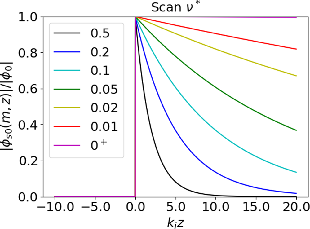
Here, H(z) is the Heaviside function. The above formula applies to positive values of k //res, for which ki > 0 and the amplitude of the RF fields decays exponentially for large positive values of z. Figure 1 plots $|{\phi _{s0}}(m,z)|/|{\phi _0}|$ from (2.19) versus kiz over a scan of the dissipation parameter ν*.


As ν* decreases to 0+, the RF fields do not diverge in the spatial domain, unlike their Fourier transform. However, the RF fields exhibit a discontinuity in z = 0, even for finite ν*. In addition, the characteristic decay length $1/{\nu ^\ast }{k_i}$ gets very large and the RF fields exhibit nearly harmonic oscillations for z > 0. One can extrapolate formula (2.19) to ν* = 0. However, the resulting RF fields are not square-integrable anymore, and therefore one cannot apply the Fourier treatments (e.g. Parseval's theorem) in a standard way. Throughout the document, we will assume that the FAMC mode is weakly damped, i.e. the ordering ${\nu ^\ast }{k_i} \ll {k_{/{/}\,\textrm{res}}}$
 applies, so that the FAMC modes possess a well-defined resonant parallel wave vector. Section 5.1 discusses this ordering.
Associated with the above RF electric fields one can define a Poynting flux P RF(z) across each plane z = const. For quasi-static cylindrical FAMC modes, Appendix A shows that the Poynting flux takes the form (A13)

For one isolated weakly damped FAMC mode this simplifies to leading order in the small parameter ${\nu ^\ast }{k_i}/{k_{/{/}\,\textrm{res}}}$

In this expression, Y FAMC has the dimension of an admittance, and depends only on the Hermitian part of the dielectric tensor; ${Z_0} \equiv {({\mu _0}/{\varepsilon _0})^{1/2}}$ is the characteristic impedance of vacuum and n //res is the resonant parallel refractive index k //res/k 0. As already noticed in Tierens et al. (Reference Tierens, Bilato, Bertelli, Shiraiwa, Myra and Colas2022a), the power flux of the FAMC mode is proportional to the local plasma density and is a fraction of the HHFW spectral power launched by the antenna at k // = k //res. For z > 0, P RF(z) decreases with z, with a decay length $1/2{\nu ^\ast }{k_i}$
 . Using Poynting's theorem, Appendix A shows that the decay is due to power dissipation in the plasma volume. The total loss over the magnetic field line is

This coincides with the power loss estimated in Tierens et al. (Reference Tierens, Bilato, Bertelli, Shiraiwa, Myra and Colas2022a) using a spectral approach. As already noticed in Tierens et al. (Reference Tierens, Bilato, Bertelli, Shiraiwa, Myra and Colas2022a), the total loss becomes independent of ν* in the weak dissipation limit. This counter-intuitive result stresses the need to regularize the initial scattering problem and to take the friction-less limit only at the end of the calculations, in order to obtain valid results. The local power loss in a thin parallel layer at position z, per unit of parallel length, is $- {\partial _z}{P_{\textrm{RF}}}(z)$ . From (2.21)

Let us first focus on z ≠ 0 and discuss the first term on the right-hand side. As ${\nu ^\ast } \to 0$ at fixed z, ${P_{\textrm{RF}}}(z) \to {P_{\textrm{RF}}}({0^ + })$
 and the local loss scales as ${\nu ^\ast }{P_{\textrm{RF}}}({0^ + })$
 . In the global power balance, this decrease with lower ν* is compensated for by the fact that the power is dissipated over a larger parallel decay length. Formula (2.23) shows that the ratio ${\mathop{\rm Im}\nolimits} ({k_{/{/}}}) \equiv {P^{\prime}_V}(z)/2{P_{\textrm{RF}}}(z)$
 , together with the expressions of ${P^{\prime}_V}(z)$
 and P RF(z) in Appendix A, provide an alternative definition of the parallel decay length of the FAMC mode, for any form of the anti-symmetric part of the dielectric tensor, in the weak damping regime. Then, Im(k //)/k //res writes

This could be a way to incorporate other dissipation processes than the present phenomenological friction, as Raether (Reference Raether1988) and Girka & Thumm (Reference Girka and Thumm2022) did for other types of surface waves. We can generalize most of the formulas below by substituting ${\nu ^\ast }{k_i} \to {\mathop{\rm Im}\nolimits} ({k_{/{/}}})$ .
Because of the local RF field discontinuity at z = 0 in (2.19), the Poynting flux in (2.21) also exhibits a discontinuity there, that is responsible for the second term on the right-hand side of (2.23). The power step ${P_{\textrm{in}}} \equiv {P_{\textrm{RF}}}({0^ + }) - {P_{\textrm{RF}}}({0^ - })$ coincides with the total power dissipated over the domain z ≠ 0. Since it is the only power source in our model, it is tempting to interpret P in as the HHFW power fraction ‘redirected’ into the FAMC mode by the scattering of the incident HHFW wave. Since z = 0 is the only location where some RF power is ‘injected’ into the FAMC mode, it is also tempting to identify it with a typical parallel position of the HHFW antenna. Finite element modelling of the HHFW scattering process supports this interpretation (Zhang et al. Reference Zhang, Tierens, Bobkov, Cathey, Cziegler, Griener, Hoelzl and Cardaun2021); large modifications of the parallel Poynting fluxes are observed near the toroidal position of the radiating straps.
2.3. Parallel symmetry properties of the RF electric fields
While we have so far considered positive values of k //res, resonant parallel wave vectors may also be negative. For symmetry reasons, if k //res fulfils the FAMC dispersion relation (2.15), so does −k //res. In this process, k ⊥ remains invariant while ki transforms into –ki. In order to fulfil the boundary conditions at the extremities of open magnetic field lines, we will need to combine FAMC modes with opposite parallel wave vectors. Therefore, we need to extend the previous formulas. While the spectral results up to (2.18) are valid for both signs of k //res, the spatial representation (2.19) of the RF fields needs to be adapted to ensure the regularity of the solution when ki < 0. For k //res < 0, the inverse Fourier transform of (2.16) yields

i.e. when ${k_{/{/}\,\textrm{res}}} \to - {k_{/{/}\,\textrm{res}}},\;{\phi _{s0}}(m,z) \to - {\phi _{s0}}(m, - z)$ and the scattered electric field components transform as ${E_{/{/}}}(r,\theta ,z) \to + {E_{/{/}}}(r,\theta , - z)\;\textrm{and}\;{E_ \bot }(r,\theta ,z) \to - {E_ \bot }(r,\theta , - z)$
 . Now the RF fields for the FAMC modes are non-zero in the half-space z < 0. Figure 1 also applies to k //res < 0, with kiz > 0 corresponding to z < 0. The damping factor ${\nu ^\ast }{k_i}z$
 is positive for k //res < 0 and z < 0. This ensures the regularity of solution (2.25) in the spatial domain. Formula (2.20) is still valid, but instead of (2.21) the Poynting flux now reads

In this case P RF(z) < 0, i.e. the power now flows towards negative z and is null for z > 0. The power step ${P_{\textrm{in}}} = {P_{\textrm{RF}}}({0^ + }) - {P_{\textrm{RF}}}({0^ - })$ (‘redirected HHFW power’) is still positive, and is still equal to the total dissipated power ${P_{\textrm{RF}}}( - \infty ) - {P_{\textrm{RF}}}({0^ - })$
 . Formula (2.23) remains valid, and since ki < 0, the local power loss ${P^{\prime}_V}(z)$
 is positive, as it should. But the volume dissipation now occurs for z < 0.
Finally, when two FAMC modes with opposite k //res are excited simultaneously, P RF(z) is the sum of the Poynting fluxes by each FAMC mode taken individually. Therefore, the redirected powers and total dissipated powers add up in the weak damping regime. One can see this as the manifestation of the Parseval theorem, valid for infinite parallel domains in the weak dissipation limit. This property will need revision in bounded geometry.
3. The FAMC mode reflection and partial dissipation at prescribed RF sheath under normal incidence.
Section 2 showed that, as the anti-Hermitian part of the dielectric tensor vanishes, the typical parallel extent of the FAMC nearly resonant modes becomes infinite. This enables dissipation of finite power in the filament, while the local loss per unit parallel length vanishes. In the SOL, however, the field lines are bounded. For ${\nu ^\ast }{k_i}$ small enough the nearly resonant FAMC modes may reach the extremities of the open magnetic field lines before being fully damped in the plasma volume. Section 3 investigates how these modes interact with RF sheaths at one extremity of a bounded magnetic field line. We expect several physical processes:
• Part of the incident mode is reflected. In general the reflected wave is not a pure FAMC mode. We will, however, find a simplified case where it is.
• The local RF fields at the boundaries will likely excite RF sheath oscillations. The RF sheaths may thereby dissipate part of the redirected HHFW power carried by the incident FAMC mode. This process likely competes with the FAMC mode dissipation in the plasma volume.
• In addition the sheath rectification likely changes the way RF sheaths reflect the incident waves. We will neglect this process. This will yield linear boundary conditions that are tractable analytically.
Section 3 investigates these processes analytically within simplifying assumptions for the sheaths. We will thereby clarify in which conditions the ‘infinite field line model’ in § 2 remains valid in bounded geometry.
3.1. Outline of the model
Figure 2 sketches the model studied in § 3. We consider a semi-infinite magnetic field line extending from z = –∞ to z = z + > 0. We perform here for the weakly damped FAMC modes a similar analysis as Myra & Kohno (Reference Myra and Kohno2019) did for propagating electrostatic plane waves with the slow mode polarization. Consistent with (2.19) we excite, via the HHFW scattering process, an incident FAMC mode of the form

Sketch of the model studied in § 3. The two nearly resonant FAMC modes in the model have opposite parallel wave vectors and propagate along the same filament. The colour shades are representative of the amplitudes for the isolated modes. In practice, the modes interfere and the total RF field amplitudes oscillate spatially, but this is not represented. Inset: equivalent model of TEM mode reflection by loaded transmission line.

By using (2.19), we assume that the FAMC excitation is not disturbed by the presence of a field line extremity. In the semi-infinite geometry, exciting a FAMC mode with k //res < 0 yields a similar result as on infinite field lines in § 2. Throughout the rest of this document, we will therefore assume k //res > 0, ki > 0. When needed we will add a minus sign explicitly. This incident mode is excited at z = 0 and extends to z = z + > 0. At z = z +, the mode reaches a field line extremity and interacts with the sheaths. As the sheath widths in SOL plasmas are far smaller than any other characteristic parallel scale length in the system (magnetic field line extension, parallel decay length of the FAMC mode, parallel wavelength) it is legitimate to model the sheaths as boundary conditions (BCs) that the RF fields need to fulfil at z = z + (Myra Reference Myra2017). In order to keep the calculations tractable, we simplify the modelled geometry; we assume that the field lines intercept the walls at normal incidence. Section 5.2 will discuss this assumption. The RF sheath BCs then write (Myra Reference Myra2017)

Here, the ⊥ subscript refers to the directions both normal to B 0 and tangential to the boundary. The // subscript refers to the direction both parallel to B 0 and normal to the boundary. Also, V shRF and j sh are the sheath oscillating voltage and the RF current density at the sheath entrance and z sh is the sheath RF impedance. Myra (Reference Myra2017) and Myra et al. (Reference Myra, Elias, Curreli and Jenkins2021) describe its parametric dependence. In order to keep the calculations tractable, we assume below that the sheath impedance is prescribed and that the product z shε // is independent of r. Section 5.3 will discuss this assumption.
3.2. The RF field spatial structure, wave reflection coefficient
Under the above simplifying assumptions, the wave reflection problem at the sheaths is linear. In these conditions, it is possible to fulfil the sheath BCs (3.2) using a linear combination of the incident FAMC mode (3.1) and a reflected FAMC mode $\phi _0^ -$ with the same azimuthal mode number m and the opposite parallel wave vector, propagating along the same filament

Unlike the incident mode, the reflected fields are present from z = −∞ to z = z +. In addition, they are continuous at z = 0, since they are not directly excited by the HHFW scattering process. In the presence of the two modes, (3.2) writes

where we have introduced a complex wave admittance ${y_w} \equiv{-} {\omega _0}{\varepsilon _0}{\varepsilon _{/{/}}}{k_{/{/}\textrm{res}}}(1 + \textrm{i}{\nu ^\ast }{k_i}/{k_{/{/}\textrm{res}}}) ={-} {\varepsilon _{/{/}}}{n_{/{/}\textrm{res}}}(1 + \textrm{i}{\nu ^\ast }{k_i}/{k_{/{/}\textrm{res}}})/{Z_0}$ . In the weak damping regime, the wave admittance is mainly real. From (3.4) we express the complex amplitude reflection coefficient in the region z > 0

The FAMC mode reflection at the extremity of the filament is formally analogous to that of a transverse electro-magnetic (TEM) mode in a (lossy) transmission line of characteristic impedance 1/yw, loaded by the sheath impedance z sh (see inset of figure 2). In the absence of dissipation in the plasma volume and in the sheaths, ywz sh is pure imaginary. In these conditions the reflection coefficient at z = z + is of amplitude 1: $|{\phi ^ - }({z^ + })|= |{\phi ^ + }({z^ + })|$ and the mode reflection only introduces a phase shift. In the general case

The case z sh = 0 (metallic BCs) yields ${\phi ^ - } ={-} {\phi ^ + }$ , i.e. E ⊥ = 0 at z = z +, as it should. The opposite limit $|{z_{\textrm{sh}}}{y_w}|\gg 1$
 (insulating BCs) yields ${\phi ^ - } ={+} {\phi ^ + }$
 i.e. j sh = 0. As in a transmission line, the reflection is null if the sheath impedance matches the wave impedance.
3.3. Sheath oscillating properties and power dissipation
In (3.4) the quantity ${\phi ^ - } + {\phi ^ + }$ represents a sheath oscillating voltage at r = rf that we can express as a function of the incident mode amplitude


The RF voltage is null for metallic BCs. It is maximal in amplitude at r = rf. The amplitude is independent of θ. In terms of the original excitation, the sheath RF voltage scales as $|\phi _0^ + |{\rm exp} ( - {\nu ^\ast }{k_i}{z^ + })$ . Its amplitude is maximal for ${\nu ^\ast }{k_i}{z^ + } \ll 1$
 and vanishes for ${\nu ^\ast }{k_i}{z^ + } \gg 1$
 . This is a first indication that the model recalled in § 2 is valid when the parallel extent of the FAMC mode on infinite field limes is far smaller than the parallel distance to the field line extremities. Since this model assumes fixed ki, this implies either that ${z^ + } \to + \infty$
 or that ν* cannot go below some critical value. Below we will call ‘short field line limit’ the regime ${\nu ^\ast }{k_i}{z^ + } \ll 1$
 , and ‘long field line limit’ the regime ${\nu ^\ast }{k_i}{z^ + } \gg 1$
 . The RF current through the sheath is


where the quantities j sh(rf), yw, z sh are evaluated in the background plasma. The sheath RF current is null in the insulating limit. It is maximal in amplitude at r = rf. The amplitude is independent of θ. We quantify the local RF power dissipation in the sheaths as


Here again, dP shRF(rf), yw, z sh are evaluated in the background plasma. The total RF power dissipation in the sheaths is then

3.4. Power balance
In the half-plane z < 0, only the reflected FAMC mode $\phi _0^ -$ is present. In this region the Poynting flux is similar to (2.26)

In this region the Poynting flux is negative: the power flows from the FAMC excitation point towards negative z. The power dissipation in this half-plane is due to the collisional losses by the reflected mode in the plasma volume and amounts to

Since the half-plane is of infinite parallel extent, the volume power dissipation remains finite in the collision-less limit. In the region 0 < z < z + the two FAMC modes interfere. This affects the Poynting fluxes. From (2.20)

with


This yields, to first order in ν*,

To leading order in ν*, the Poynting flux in the presence of the two FAMC modes is the sum of a positive flux that would be obtained with the incident FAMC mode alone, and a negative contribution corresponding to the reflected mode alone. In the presence of volume dissipation, an additional oscillatory term of order ν* appears, due to the interference of the two modes. As $|R_\phi ^ + |< 1$ and 0 < z < z +, the leading contribution to (3.20) is positive: in this region the power flows from the FAMC excitation point towards the sheath. In addition,

The first two contributions to (3.21) are the sum of the volume losses by each FAMC mode taken individually. The third oscillatory term results from the interference of the two modes, and can be of the same order as the other ones. As ${\nu ^\ast } \to {0^ + }$ at fixed z, the local loss scales as ν*. However, now the parallel domain is of finite parallel extent, so that the cumulated volume losses ${P_{\textrm{RF}}}(0) - {P_{\textrm{RF}}}({z^ + })$
 vanish in the collision-less limit. To leading order in ν*

The redirected power is the same with the semi-infinite as with the infinite field line model. Remarkably, P in is independent of the collisionality, of the parallel distance z +, of the sheath properties and more generally independent of which physical process dissipates the FAMC modes. To leading order in ${\nu ^\ast }{k_i}/{k_{/{/}\textrm{res}}}$ , the Poynting flux at z = z + amounts to

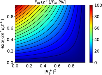
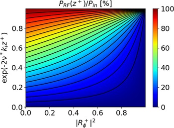
${P_{\textrm{RF}}}({z^ + })$ from (3.23) is equal to the sheath power dissipation P shRF from (3.13). Formula (3.23) provides the fraction of redirected power lost in the sheaths. Figure 3 maps ${P_{\textrm{RF}}}({z^ + })/{P_{\textrm{in}}}$
 versus $|R_\phi ^ + {|^2}$
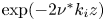
 and ${\rm exp} ( - 2{\nu ^\ast }{k_i}{z^ + })$
 . ${P_{\textrm{RF}}}({z^ + })/{P_{\textrm{in}}}$
 increases with decreasing $|R_\phi ^ + {|^2}$
 and decreasing ${\nu ^\ast }{k_i}{z^ + }$
 . Contour lines are hyperbolas with asymptotes $|R_\phi ^ + {|^2} = 1$
 and ${\rm exp} ( - 2{\nu ^\ast }{k_i}{z^ + }) = 0$
 . The RF sheaths do not dissipate all the redirected power, even when the anti-Hermitian part of the dielectric tensor vanishes. The sheath power fraction can be low for two reasons:
(1) ${\nu ^\ast }{k_i}{z^ + } \gg 1$
(long field line limit): most of the power from the incident FAMC mode is damped in the plasma volume before reaching the sheath. In this regime, the reflected FAMC mode hardly exists, the infinite field line model is fully valid.(2) $|R_\varphi ^ + |\sim 1$
: most of the power carried by the incident FAMC mode at z = z + is reflected into the mode ϕ −, and subsequently dissipated in the (infinite) plasma volume −∞ < z < z +.



4. Lossy cavity bounded by two dissipative RF sheaths.
In § 3, the reflected FAMC mode extended to z = −∞ in the limit ${\nu ^\ast } \to {0^ + }$ , when keeping all other parameters constant. This raises the question of realistic magnetic field lines in the SOL, bounded by sheaths at their two extremities. This is the topic of § 4. When two sheaths face each other, we may expect multi-reflections of FAMC modes between the two extremities, interferences all over the plasma volume, and ‘multi-pass’ wave dissipation in the plasma volume and in the sheaths, leading to a lossy cavity excited by the incident HHFW wave. Similar kinds of cavities, e.g. Fabry--Perot resonators (Renk Reference Renk2017), guide our modelling. One also meets multi-pass wave damping in ICRF heating scenarios; see e.g. Decamps et al. (Reference Decamps, Koch, Van Nieuwenhove, Van Oost, Van Wassenhove, Delvigne, Messiaen, Vandenplas and Weinants1991), Fuchs et al. (Reference Fuchs, Ram, Schultz, Bers and Lashmore-Davis1995) and Kazakov et al. (Reference Kazakov, Pavlenko, Van Eester, Weyssow and Girka2010).
4.1. Outline of the model
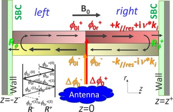
Figure 4 sketches the model studied in § 4. The bounded magnetic field line now consists of two segments [−z −,0] and [0,z +], denoted respectively left and right. In each segment there are two FAMC modes with positive wave vector +k //res > 0 (respective complex amplitudes $\phi _{0l}^ +$ and $\phi _{0r}^ +$
 at z = 0) and opposite wave vector −k //res < 0 (complex amplitudes $\phi _{0l}^ -$
 and $\phi _{0r}^ -$
 at z = 0). The mode excitation occurs at z = 0. Consistent with expressions (2.19) and (2.25), we model it as a kick on the complex amplitudes of the two modes


Sketch of the bounded field line model in § 4. The two nearly resonant FAMC modes in the model have opposite parallel wave vectors and propagate along the same filament. The colour shades are representative of the amplitudes for the isolated modes. In practice, the modes interfere and the total RF field amplitudes oscillate spatially, but this is not represented. Inset: decomposition of the solution into partial waves.

The prescribed excitation terms $\Delta \phi _0^ +$ and $\Delta \phi _0^ -$
 are respectively due to nearly resonant scattering of incoming HHFW spectral components at +k //res and −k //res. They are expressed as a function of the incident wave using formula (2.17).
We describe the propagation of the modes in segments [−z −,0] and [0,z +] and their reflection at z = z + or z = −z −, using formulas similar to (3.15) in semi-bounded geometry


and we use formulas analogous to (3.5) to express $R_\phi ^ \pm$ .
4.2. RF field structure, wave multi-reflections
Equations (4.1)–(4.4) fully define the system in terms of the excitations $\Delta \phi _0^ +$ and $\Delta \phi _0^ -$
 . One can directly solve the system, or alternatively proceed in an iterative way as in Renk (Reference Renk2017),

In the iteration rules (4.5) one can identify the generic terms, e.g. $\phi _{0r}^{ + (n)}$ , with the complex amplitudes of ‘partial waves’ at z = 0, after n reflections on the left and right boundaries. Within this interpretation the kicks at n = 0 represent the amplitudes of the FAMC modes excited by the HHFW scattering process, before the first double reflection. These are responsible for the RF field discontinuity at z = 0. One subsequently obtains the solution as a ‘global wave’, i.e. the superposition of partial wave complex amplitudes, allowing for interference

For n > 1, each double reflection multiplies the partial wave amplitudes by R +R −. One can decompose the coefficient R + into an amplitude attenuation factor and a phase shift on the right part of the bounded magnetic field line

A similar formula applies on the left side. In relation to the prototype Fabry--Perot resonator (Renk Reference Renk2017), $|R_\phi ^ + R_\phi ^ - |$ quantifies the reflectivity of the cavity extremities, while ${\rm exp} ( - 2{\nu ^\ast }{k_i}({z^ + } + {z^ - }))$
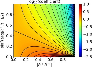
 quantifies the ‘gain’ (actually a loss <1) of the medium. The phase shift between successive partial waves is arg(R +R −), while the ‘single-pass attenuation’ due to dissipation is |R +R −|. In the presence of dissipation, |R +R −| < 1 and the series converges. The behaviour of 1/(1−R +R −) is therefore a direct consequence of the interference between multiple partial waves.

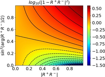
Figure 5 plots |1−R +R −|2 versus |R +R −| and $\textrm{si}{\textrm{n}^2}[\textrm{arg(}{R^ + }{R^ - }\textrm{)}/2]$ . The number of partial waves to take into account (number of roundtrip transits for FAMC mode photons) is typically 1/1−|R +R −| (Renk Reference Renk2017). In the long field line limit ${\nu ^\ast }{k_i}{z^ - } \to + \infty$
 , one partial wave is enough: R −→0 and one recovers on the right side of the field line the semi-bounded model in § 3. This semi-bounded model also applies to the left side if $\Delta \phi _0^ -{=} 0$
 (no direct excitation of the FAMC mode at –k //res). The opposite limit is more interesting to study. The interference between partial waves in (4.6) manifests in oscillatory terms on the mode amplitudes, persisting in the short field line limit ${\nu ^\ast }{k_i}{z^ - } \to 0$
 and ${\nu ^\ast }{k_i}{z^ + } \to 0$
 . As arg(R +R −) spans $[0,\mathrm{\pi }],\;|1 - {R^ + }{R^ - }{|^2}$
 ranges between ${(1 - |{R^ + }{R^ - }|)^2} < 1$
 and ${(1 - |{R^ + }{R^ - }|)^2} > 1$
 . The factor is smaller than 1 if

so 1/|1−R +R −| can grow very large if the ‘single-pass attenuation’ is weak (|R +R −| close to 1) and simultaneously the partial waves interfere constructively $({\sin ^2}(\arg ({R^ + }{R^ - })/2) \ll 1)$ . This situation is characteristic of a resonant cavity with a large quality factor (Renk Reference Renk2017). In conditions of weak dissipation one can approximate (4.8) as

Colour map (log scale) of $|1 - {R^ + }{R^ - }{|^2}$ versus $|{R^ + }{R^ - }|$
 and ${\sin ^2}(\arg ({R^ + }{R^ - })/2)$
 , together with contour lines. The straight line corresponds to $|1 - {R^ + }{R^ - }|= 1$
 ((4.9)), the dashed curves are contour lines for $|1 - {R^ + }{R^ - }{|^2} < 1$
 .

4.3. Redirected Power
On the parallel segment [0,z +], a formula similar to (3.20) applies for the Poynting flux, where one replaces $\phi _0^ +$ with $(\Delta \phi _0^ +{-} {R^ - }\Delta \phi _0^ - )/(1 - {R^ + }{R^ - })$


As already noticed in (3.20) and (3.21), P RF(z) > 0 and ∂zP RF(z) < 0 on the right side of the magnetic field line. Similarly on the left side [−z −,0].

On this segment P RF(z) < 0 and ∂zP RF(z) < 0. We deduce the redirected power

In order to compare with previous models, let us first take one single FAMC mode excitation and assume $\Delta \phi _0^ - = 0$ . Then

As already noticed in § 3, the redirected power depends only on R +R −, regardless of which physical process dissipates the power. Compared with the ‘infinite field line model’, the redirected power is multiplied by the factor

In this expression, $1 - |{R^ + }{R^ - }{|^2}$ quantifies the power dissipated in one pass by a partial wave of amplitude 1, while 1/|1−R +R −| quantifies the enhancement of amplitude for the global wave due to the multi-reflections. Figure 6 plots the multiplication factor (4.15) versus |R +R −| and ${\sin ^2}(\arg ({R^ + }{R^ - })/2)$
 . At fixed |R +R −|, figure 6 displays Airy curves characteristic of a Fabry--Perot cavity (Renk Reference Renk2017): as arg(R +R −) increases from 0 (constructive interference) to π (destructive interference), the factor decreases from $(1 + |{R^ + }{R^ - }|)/(1 - |{R^ + }{R^ - }|) > 1$
 (amplification) to $(1 - |{R^ + }{R^ - }|)/(1 + |{R^ + }{R^ - }|) < 1$
 (reduction). The factor is larger than 1 if

(straight line in contour plot).


The range of the variation broadens as |R +R −| increases. For $|{R^ + }{R^ - }|\ll 1$ one recovers the infinite field line model (factor 1), regardless of the dissipation process. This also applies to the semi-bounded field line model, for which R − = 0. When |R +R −| is close to 1 and arg(R +R −) close to 0, the multiplication factor becomes very sensitive to small changes in the parameters: formula (4.15) behaves locally as the ratio $(1 - |{R^ + }{R^ - }|)/2\textrm{si}{\textrm{n}^2}(\textrm{arg(}{R^ + }{R^ - }\textrm{)}/2)$
 . In figure 6 the contour curves appear locally as straight lines converging at the critical point. This behaviour is characteristic of a high-Q resonant cavity, with a quality factor proportional to 1/(1−|R +R −|) (Renk Reference Renk2017). The half-width of the resonant peak scales as $|{R^ + }{R^ - }{|^{1/2}}/(1 - |{R^ + }{R^ - }|)$
 .
When the HHFW scattering process simultaneously excites two counter-propagative modes $\Delta \phi _0^ +$ and $\Delta \phi _0^ -$
 in the system, the dissipated power is NOT the sum of the dissipated powers by each mode excited separately with the same amplitude. In other words the Parseval theorem, as formulated on infinite field lines, does not apply to the bounded magnetic field line. This is also a consequence of the mode reflections. Instead, (4.11) shows that ${P_{\textrm{rf}}}({0^ + })$
 is proportional to $|\Delta \phi _0^ +{-} {R^ - }\Delta \phi _0^ - {|^2}$
 , while (4.12) shows that ${P_{\textrm{rf}}}({0^ - })$
 is proportional to $|\Delta \phi _0^ -{-} {R^ + }\Delta \phi _0^ + {|^2}$
 .
4.3. Sheath oscillating properties and power partitioning.
On the bounded field line model, the sheath RF voltages are analogous to expression (3.8) for the isolated sheath in § 3, upon the substitution $\phi _0^ + \to \phi _{0r}^ +{=} (\Delta \phi _0^ +{-} {R^ - }\Delta \phi _0^ - )/(1 - {R^ + }{R^ - })$ or $\phi _{0l}^ -{=} - (\Delta \phi _0^ -{-} {R^ + }\Delta \phi _0^ + )/(1 - {R^ + }{R^ - })$


Depending on the excitation and on the interference patterns, the amplitudes of sheath oscillations can differ at the two extremities of the bounded field line. As ${\nu ^\ast }{k_i}{z^ - } \to + \infty$ , the sheath oscillations on the left side tend to 0, and one recovers exactly expression (3.8) on the right sheath. The sheath voltages are proportional to the local wave amplitudes; when $\Delta \phi _0^ -{=} 0$
 , the voltage on the right sheath is multiplied by a factor $1/|1 - {R^ + }{R^ - }|$
 compared with (3.8). The power losses at the sheaths also exhibit similarity with previous results

These power fractions are independent of arg(R +) and arg(R −). In addition, the power fractions on the two sides of the magnetic field line are independent of each other. Figure 7 maps ${P_{\textrm{RF}}}({z^ + })/{P_{\textrm{RF}}}({0^ + })$ versus $|R_\phi ^ + {|^2}$
 and ${\rm exp} ( - 2{\nu ^\ast }{k_i}{z^ + })$
 . ${P_{\textrm{RF}}}({z^ + })/{P_{\textrm{RF}}}({0^ + })$
 increases with decreasing $|R_\phi ^ + {|^2}$
 and decreasing ${\nu ^\ast }{k_i}{z^ + }$
 . As already observed on the right segment in § 3, in the presence of dissipative sheaths


Consequently, in the short field line limit ${\nu ^\ast }{k_i}{z^ - } \to 0$ and ${\nu ^\ast }{k_i}{z^ + } \to 0$
 , the sheaths dissipate all the redirected power. One could anticipate this result; the magnetic field line has a finite parallel extent, so that the volume dissipation vanishes in the collision-less limit, despite a possible RF field enhancement by multi-reflection. The only exception to property (4.19) occurs when one replaces both sheaths by perfect metallic walls. In that case $|R_\phi ^ + |= 1$
 and $|R_\phi ^ - |= 1$
 , all the redirected power is dissipated in the plasma volume even in the short field line limit. When $|R_\phi ^ + |$
 is close to 1 and ${\nu ^\ast }{k_i}{z^ + }$
 is small (upper-right corner of figure 7), ${P_{\textrm{RF}}}({z^ + })/{P_{\textrm{RF}}}({0^ + })$
 is very sensitive to small changes in the parameters. The power ratio locally behaves as

One can see the fraction of redirected power lost in the sheaths as a weighted average of formulas (4.18) on the two sides of the magnetic field line

When the field line geometry is left--right symmetric, i.e. $|R_\phi ^ + |= |R_\phi ^ - |$ and z + = z −, one finds a result similar to (4.18)

This fraction is larger than the previous result (3.23) for semi-bounded magnetic field lines, by a factor $1/[1 - |R_\phi ^ + {|^2}\textrm{exp}({-} 4{\nu ^\mathrm{\ast }}{k_i}{z^ + }\textrm{)}]$ . When the magnetic field line is asymmetric but $\Delta \phi _0^ -{=} 0$
 , the power fraction lost in the sheaths amounts to

One recovers formula (3.23) in the long field line limit on the left side $({\nu ^\ast }{k_i}{z^ - } \gg 1)$ , as well as (4.22) for a left--right symmetric system. It simplifies to ${\rm exp} ( - 2{\nu ^\ast }{k_i}{z^ + })$
 when $|R_\phi ^ + |= 0$
 .
5. Discussion of the simplifying assumptions in the above models
5.1. Weakly damped FAMC mode.
Throughout the document we have applied the weak damping ordering ${\nu ^\ast }{k_i} \ll {k_{/{/}}}$ for the FAMC modes. This simplifies the formulas for the Poynting fluxes. Figure 8 plots ki/k //res versus ξ res of the FAMC mode for several harmonics ω/Ω ci, from formula (2.18) using the tensor elements (2.4)–(2.7). To produce the graph, we followed the same procedure as in Tierens et al. (Reference Tierens, Bilato, Bertelli, Shiraiwa, Myra and Colas2022a). We chose the values of m, ξ res and ω/Ω ci. We then deduced the value of the resonant density ratio nf/nb in order to fulfil the FAMC dispersion relation (2.15). The solution may not exist if k //res is too large. We finally inserted all the FAMC parameters into expression (2.18). Figure 8 shows that over the parametric domain under study, ki/k //res is of order unity. Therefore weak damping essentially occurs if ${\nu ^\ast } \ll 1$
 . Following Tierens et al. (Reference Tierens, Bilato, Bertelli, Shiraiwa, Myra and Colas2022a), one can interpret the anti-Hermitian part of the dielectric tensor as artificial dissipation, i.e. as a mathematical way to regularize the HHFW scattering problem in a collision-less plasma, without clear physical counterpart. The essence of this approach is to let ν*→0 at the end of the calculations, and the weak damping ordering becomes legitimate in this limit. Alternatively one can interpret the volume dissipation as a simplified way to account for a physical friction with an immobile background, e.g. with residual neutrals in the SOL. Within this interpretation the friction parameters ν* expected in typical SOL plasmas are far less than 1. Therefore, the weak damping ordering should also be valid in the case of physical friction.
Resonant density ratio nf/nb and wave vector ratio ki/k //res vs ξ res for a FAMC mode with azimuthal number m = 1, and several harmonics ω/Ω ci. For information, the graph also shows the k //res associated with ξ res for deuterium ions and a filament radius rf = 1 cm.

Formula (2.24) generalized the expression of Im(k //). It shows that, as long as the anti-Hermitian part of the dielectric tensor remains negligible with respect to the Hermitian part, we expect ${\mathop{\rm Im}\nolimits} ({k_{/{/}}}) \ll {k_{/{/}\,\textrm{res}}}$ .
5.2. Modelled geometry.
We have envisaged cylindrical filaments, aligned with a straight confinement magnetic field and homogeneous in the parallel direction. This is necessary to carry out simple analytical calculations in cylindrical geometry, and is motivated by the small transverse scale lengths of the filament, in comparison with characteristic parallel lengths in the problem. Turbulent filaments measured in the SOL of NSTX are field-aligned structures, but their transverse cross-section is generally not circular (Zweben et al. Reference Zweben, Myra, Davis, D'Ippolito, Gray, Kaye, LeBlanc, Maqueda, Russel and Stotler2016). In addition, the filament typical transverse dimension may be comparable to typical density gradient lengths in the quiescent plasma background. Tierens et al. (Reference Tierens, Zhang and Manz2020b) investigated numerically FAMC modes in a less idealized geometry, showing that both the transverse structure of the mode and its resonant parallel wave vector could depend sensitively on the details of the density distribution in the background plasma and inside the filament. Yet the more realistic models in Tierens et al. (Reference Tierens, Zhang and Manz2020b) do preserve the parallel symmetry properties outlined in § 2.3, that are essential to the mode reflection processes in § 3.
In the parallel direction, the filaments may not extend all along the magnetic flux tubes to their extremities. At least the density ratio nf/nb (hence k //res, k ⊥, ki…) may vary in the parallel direction. This is particularly true on the high-field side of the torus, on the way towards the inner divertor targets, where the curvature of the magnetic field lines is favourable (Scotti et al. Reference Scotti, Zweben, Myra, Maqueda and Soukhavovski2020). Experiments, however, suggest RF sheath excitation at some field line extremities on NSTX (Perkins et al. Reference Perkins, Hosea, Jaworski, Ahn, Diallo, Bell, Bertelli, Gerhardt, Gray, Krammer, LeBlanc, McLean, Phillips, Podesta, Roquemore, Saggagh, Taylor and Wilson2015, Reference Perkins, Hosea, Jaworski, Bell, Bertelli, Kramer, Roquemore, Taylor and Wilson2017). If the filaments vanish smoothly enough in the parallel direction, the FAMC modes may reflect in the plasma volume before reaching the sheaths. It may be possible to account for this effect within the present models, by adapting both the field line lengths $({z^ + },{z^ - })$ and the reflection coefficients $(R_\phi ^ + ,R_\phi ^ - )$
 .
We assumed that the filaments impinge onto the sheath boundaries at normal incidence. This assumption is necessary to fulfil the sheath BCs using two FAMC modes with the same azimuthal mode number and opposite parallel wave vectors. This normal incidence is doubtful for magnetic flux tubes in the SOL, especially in the divertor region, rather shaped for grazing incidence of the field lines. The incidence could be different at the two extremities of the magnetic field lines. This non-ideality breaks the cylindrical symmetry of the initial geometry. The reflected wave may therefore involve several azimuthal mode numbers. Oblique incidence also mixes of the parallel and transverse electric fields in the RF sheath BCs. Dispersion relation (2.10) implies that the ratio |E ///E ⊥| for electrostatic modes is typically ${({\varepsilon _ \bot }/{\varepsilon _{/{/}}})^{1/2}} = {({m_e}/{M_i})^{1/2}}$ . Therefore the mix becomes non-negligible for small deviations from normal incidence, of the order of ${({m_e}/{M_i})^{1/2}}$
 . Due to this non-ideality, part of the incident wave reflects into other wave types, generally not FAMC filament modes. For plane waves, (Myra & Kohno (Reference Myra and Kohno2019) showed that, at oblique incidence, the incident and reflected modes have different wave vectors normal to the planar boundary.
5.3. Radial invariance of ywz sh?
When one nearly resonant mode impinges onto the sheaths, the radial invariance of ywz sh ensures that the reflected wave consists only of the FAMC mode with the opposite parallel wave vector. The wave impedance yw is proportional to ε //, i.e. the local plasma density. In our models it takes two different values inside and outside the filament. In the more realistic models of Tierens et al. (Reference Tierens, Zhang and Manz2020b) the variations are even more complicated; z sh also depends on r, it changes with the local plasma density and with the local sheath RF voltage, two quantities varying radially. The local sheath voltage depends a priori on the local sheath impedance. Consequently, rigorous calculations should, in principle, be nonlinear and self-consistent, while the simplified approach in §§ 3 and 4 was linear with prescribed sheath impedance. More specifically, Myra (Reference Myra2017) and Myra et al. (Reference Myra, Elias, Curreli and Jenkins2021) proposed a parametrization of the sheath impedance. At normal field line incidence, it takes the form

where Te is the local electron temperature, while ${c_s} \equiv \sqrt {k{T_e}/{M_i}}$ is the sound speed in the presence of cold ions. Taking $Re(\varepsilon _{/{/}})\sim{-} \omega _{\textrm{pe}}^2/\omega _0^2$
 , the product ywz sh writes

In our models, the pre-factor in (5.2) is radially invariant. We still have to discuss the parametric dependence of the normalized sheath impedance ${\bar{z}_{\textrm{sh}}}$ . At low frequencies or high densities ${\omega _0}/{\omega _{\textrm{pi}}} \ll 1$
 , the electronic contribution generally dominates the RF impedance. Within a single-plate model of the RF sheath, this contribution takes the form

This normalized impedance is independent of the local density. It is constant for $e{V_{\textrm{shRF}}} \ll k{T_e}$ , and proportional to $e{V_{\textrm{shRF}}} / k{T_e}$
 for large sheath oscillating voltages (the most interesting situation). For a typical NSTX case, the HHFW frequency is ~30 MHz, and the criterion ${\omega _0}/{\omega _{\textrm{pi}}} \ll 1$
 defines a critical density ${n_e} \gg 4 \times {10^{16}}\;{\textrm{m}^{ - 3}}$
 . Therefore, formula (5.3) is suitable in the SOL region of NSTX where filaments interact with HHFW. In the opposite limit ${\omega _0}/{\omega _{\textrm{pi}}} \gg 1$
 (large frequency, low density), capacitive displacement currents generally dominate the RF impedance. The normalized RF impedance scales as

So, aside from asymptotic regimes (metallic or insulating BCs), for which the sheath losses vanish, the assumption of radial invariance is approximate. The approximation needs assessment but may be not so bad because:
• The dispersion relation (2.15) can ‘select’ filaments with large density ratios (see e.g. figure 8), for which our assumptions are doubtful. Yet most of the filaments observed in the SOL of NSTX have nf/nb close to 1 (Zweben et al. Reference Zweben, Myra, Davis, D'Ippolito, Gray, Kaye, LeBlanc, Maqueda, Russel and Stotler2016). Over a statistical average, these will likely dominate the results.
• V shRF is a smooth function of the radius r, but it may be steep near the filament boundary. What may matter most for the mode reflection is the region close to the filament boundary, where the sheath RF voltage is maximal.
The nonlinearity of z sh complicates the resonance of the cavity :
– Near the resonance, the amplitude of the sheath RF voltages is sensitive to $1 - |{R_\phi }{|^2}$
.– via the nonlinear z sh, $|{R_\phi }{|^2}$
depends on the amplitude of the sheath RF voltages.


Another consequence of the non-ideality is that part of the incoming FAMC mode may reflect into other wave types, generally not FAMC filament modes. This process might therefore dissipate part of the redirected power outside the sheaths, even in the collision-less limit. In terms of the electromagnetic cavity defined in § 4, one can view this process as a loss mechanism broadening the resonance of the cavity and reducing its quality factor. Renk (Reference Renk2017) proposes several generalizations of the Fabry--Perot resonator model. Along this line of thought one could possibly adapt the above theory using ad hoc ‘effective reflection coefficients’ for the FAMC modes in the sheath, whose amplitude would be smaller than the ‘ideal reflection coefficients’ in §§ 3 and 4. With this definition, the power carried by the incident FAMC mode would be larger than the power reflected in the other FAMC mode plus the power dissipated in the sheath. One could possibly quantify these effective coefficients numerically from more sophisticated (and more demanding) nonlinear full wave simulations.
5.4. Limitations of the redirected power.
We assumed that the presence of field line extremities did not affect the FAMC mode excitation. Figure 6 suggests that in some conditions the redirected power may become very large. In these conditions the redirected power is very sensitive to the value of k //res. In practice, the redirected power cannot exceed the finite amount of power initially launched by the HHFW antenna. The discussion above suggests that the resonant cavity conditions are hard to reach. More fundamentally, the infinite field line model in § 2.1 assumed that the scattering process does not modify the incident HHFW. Using this model, Tierens et al. (Reference Tierens, Bilato, Bertelli, Shiraiwa, Myra and Colas2022a,Reference Tierens, Myra, Bilato and Colasb) estimated that the fraction of HHFW power redirected into the FAMC mode is in the range 0.1 % per typical filament observed in NSTX. The high sensitivity on k //res may violate an underlying assumption used to obtain (2.16); ${\nu ^\ast }{k_i}$ should be the shortest wavenumber in the spectral problem. In the presence of strong power redirection, we expect a retroaction of the FAMC mode onto the incident HHFW wave to keep the redirected power fraction below 1. In a slightly different context, Decamps et al. (Reference Decamps, Koch, Van Nieuwenhove, Van Oost, Van Wassenhove, Delvigne, Messiaen, Vandenplas and Weinants1991) showed that exciting ICRF cavity modes can affect the load resistance of the ICRF antenna.
6. Conclusions and outlook
This contribution compared analytically the parallel propagation, reflection and dissipation of nearly resonant FAMC modes in three magnetic field line geometries, in the presence of both RF sheaths and wave damping in the plasma volume. The simple formalism developed in this paper is not specific of FAMC modes. One can apply it to other kinds of surface waves or guided modes for which the spectral resonance (2.16) appears, in contexts different from a tokamak SOL. For example, we found some analogy with loaded transmission lines. Appendix A envisaged a general form for the anti-Hermitian part of the dielectric tensor. Table 1 summarizes our main findings.
Main properties of FAMC mode model in the three field line geometries studied in the main text.

The FAMC modes can possibly propagate along large parallel distances and excite RF sheaths far away toroidally from the HHFW launchers. A typical parallel extent of the FAMC mode in unbounded field lines is $1/({\nu ^\ast }{k_i})$ . When the magnetic field lines impinge onto the walls at normal incidence, the paper described analytically how RF sheaths reflect an incident FAMC mode into another FAMC mode with the opposite resonant parallel wave vector. As in Myra & Kohno (Reference Myra and Kohno2019) for plane electrostatic waves, the ‘single-pass’ reflection coefficient $R_\phi ^ +$
 depends on the product of the sheath RF impedance by the wave admittance of the FAMC mode. The sheath RF voltages are proportional to the local amplitude of the incident FAMC modes and to $|1 + R_\phi ^ + |$
 . Section 5 suggested that, in more realistic tokamak situations, the incident FAMC mode may partly reflect into non-FAMC waves.
The FAMC modes divert some fraction of the spectral HHFW power launched into the plasma at the resonant wave vector k // = k //res. In the weak damping regime considered here $({\nu ^\ast }{k_i} \ll {k_{/{/}\textrm{res}}})$ , this fraction is independent of which physical mechanism dissipates the power: it depends only on R +R −, the complex factor that multiplies the partial FAMC mode amplitudes after one reflection at each field line extremity. In the limit $|{R^ + }{R^ - }| \ll 1$
 (strong ‘single-pass’ damping), the ‘infinite field line’ FAMC model in Tierens et al. (Reference Tierens, Bilato, Bertelli, Shiraiwa, Myra and Colas2022a) yields the correct power, even in bounded geometry. In the opposite limit (|R +R −| close to 1), the bounded magnetic field line behaves like a resonant cavity for the FAMC modes, similar to a Fabry--Perot resonator (Renk Reference Renk2017). The total redirected power then becomes sensitive to small variations in the parameters of the model, via |R +R −| and the single-pass phase shift arg(R +R −). Section 5 suggests, however, that reaching this resonant cavity regime is unlikely in realistic tokamak situations.
In our model, the HHFW power diverted into the FAMC modes can damp either in the plasma volume or in RF sheaths. In a left--right symmetric bounded magnetic field line, the power partitioning depends on two parameters: $|R_\phi ^ + {|^2}$ and ${\rm exp} ( - 2{\nu ^\ast }{k_i}{z^ + })$
 , the ‘single-pass’ volume dissipation factor. One can see the argument of the exponential as the ratio of the field line length 2z + over the parallel extension of the FAMC mode in unbounded geometry. In the ‘long field line’ limit ${\nu ^\ast }{k_i}{z^ + } \gg 1$
 , one recovers the ‘infinite field line’ model (Tierens et al. Reference Tierens, Bilato, Bertelli, Shiraiwa, Myra and Colas2022a), where RF sheath excitation is modest and volume dissipation dominates. When the anti-Hermitian part of the dielectric tensor vanishes, one can reach this ‘long field line limit’ only with infinite flux tubes. In the opposite limit ${\nu ^\ast }{k_i}{z^ + } \to 0$
 , the sheaths dissipate all the redirected power, even when the ‘single-pass’ sheath absorption is modest. This happens because in our lossy cavity model, sheaths are the only power loss channel remaining on ‘short field lines’. Section 5 outlined, however, several alternative ways for the redirected HHFW power to ‘leak’ from the physical system in more realistic tokamak situations. The fate of this ‘leaking power’ is still an open question. The semi-bounded field line model provides an intermediate power sharing; the total field line length is infinite, but the sheath is located at finite distance from the FAMC excitation point z = 0.
Like the ‘infinite field line FAMC model’ in Tierens et al. (Reference Tierens, Myra, Bilato and Colas2022b), the proposed bounded field line model deserves comparison with HHFW experiments, in particular the RF sheath behaviour on NSTX, not addressed so far (Perkins et al. Reference Perkins, Hosea, Jaworski, Ahn, Diallo, Bell, Bertelli, Gerhardt, Gray, Krammer, LeBlanc, McLean, Phillips, Podesta, Roquemore, Saggagh, Taylor and Wilson2015, Reference Perkins, Hosea, Jaworski, Bell, Bertelli, Kramer, Roquemore, Taylor and Wilson2017). For this first exploration, we have adopted a simple analytical approach relying on many idealizations. Section 5 suggests that several assumptions are questionable in realistic tokamak cases and outlined several areas of improvement. One can likely attempt more realistic FAMC modelling numerically. We expect this effort to be much heavier computationally than our simple approach and therefore leave it for further work. Section 5 suggested that one could possibly use the numerical results to adapt the main parameters identified in our analytical models.
Acknowledgements
Editor Peter Catto thanks the referees for their advice in evaluating this article.
Declaration of interests
The authors report no conflict of interest.
Funding
One of us (J.R.M.) acknowledges support for this work by the U.S. Department of Energy, Office of Science, Office of Fusion Energy Sciences, under Award Number DE-FG02-97ER54392.
Appendix A. Poynting theorem reformulated for quasi-electrostatic cylindrical filament modes
This appendix reformulates the Poynting theorem for quasi-electrostatic cylindrical filament modes, such as those introduced in Tierens et al. (Reference Tierens, Bilato, Bertelli, Shiraiwa, Myra and Colas2022a) and investigated throughout this document. We are interested in the following form of the Poynting relation

where ${P^{\prime}_V}(z)$ is the power dissipated in a thin plasma layer at z = const., per unit of axial length, and P RF(z) is the Poynting flux across the plane z = const.
A.1. Power dissipation in the plasma volume
We first evaluate the power loss ${P^{\prime}_V}(z)$ in the plasma volume

As the studied cylindrical modes oscillate azimuthally as ${\rm exp} (\textrm{i}m\theta ),{\boldsymbol{E}^\ast }\boldsymbol{\cdot }\boldsymbol{D}$ is independent of θ

Let us now introduce the quasi-electrostatic assumption E = −∇ϕ, and the definition D ≡ ε 0εE

One can identify three contributions to ${P^{\prime}_V}(z)$ related to the three dielectric constants

where


To evaluate ${P^{\prime}_{V \times }}(z)$ we notice that |ϕ| vanishes at r = 0 and r→+∞, while the dielectric tensor ε exhibits an abrupt step at the filament boundary r = rf. Associated with this step is a discontinuity of some RF field components at r = rf. For any discontinuous quantity F(r) we will note [[F]] the step at r = rf, i.e.

Consistent with standard continuity conditions between two media (Stix Reference Stix1992) (see also Tierens et al. Reference Tierens, Bilato, Bertelli, Shiraiwa, Myra and Colas2022a), we assume below $[[\phi ]] = 0,\;[[{H_\theta }]] = 0,\;[[{D_r}]] = 0$

A.2. Poynting flux
We now evaluate the Poynting flux P RF(z)

Let us introduce the quasi-electrostatic approximation and integrate by parts

Here, we implicitly used [[ϕ]] = 0 and [[Hθ]] = 0 at the filament boundary. We now recall Maxwell--Ampère equation

We obtain

Let us take the axial derivative of the latter expression

with


To evaluate ${P^{\prime}_2}(z)$ we use the dispersion relation (2.3) for the electrostatic mode

Let us integrate by parts, and take into account the discontinuities at the filament boundary

We re-express the first term on the right-hand side using [[ϕ]] = 0 and [[Dr]] = 0, i.e. $r\left[\left[{\varepsilon _ \bot }{\partial _r}\phi\right]\right] ={-} m\phi \left[\left[{\varepsilon _ \times }\right]\right]$

In summary

This is the requested reformulation.