NOMENCLATURE
Abbreviations
- DSE
design space exploration
- FE
finite element
- 2D
two-dimensional
- 3D
three-dimensional
Symbols
 $r$, $\varphi $, $z$
components of the cylindrical coordinate system
- H
flange height selected for parametric variation
- P
flange positioning selected for parametric variation
- p
pressure
- T
sink temperature
- W
flange width selected for parametric variation
- α
heat transfer coefficient
- μ
mean value
- $ \sigma$
standard deviation


Subscripts
- a
surface of the outer side of the casing
- c
stator cavity surfaces wetted with leakage flow
- i
surface of the inner side of the casing
- m
surface of the inner casing structures
- p
peripheral surfaces of the casing
1.0 INTRODUCTION
Reducing costs by reducing the time to market from the first concept to implementation of the final product is of major interest in aero-engine development processes. In particular, multidisciplinary modelling in the preliminary design phase of aero-engines includes significant potential for early process optimisation. The present project concentrates on the development of a preliminary aero-engine axial compressor casing design methodology, involving meta-modelling techniques and approaches for numerical model simplification. Proceeding from an initial casing geometry and based on given rotor expansions, a method allowing prompt tip clearance assessments is developed.
Because of the changing thermal as well as pressure-driven expansion and centrifugal forces during engine operation, the tip clearance, defined as the radial distance between the rotor blade tips and the casing, has a transient character. Generally, the losses induced by tip clearance correlate with the relative ratio of the blade height to the tip clearance gap width(Reference Hupfer1-Reference Guinet and Hupfer3). The tendency in future compressors towards lower blade heights exacerbates the impact of such losses due to the increase of the relative tip clearance values, resulting in decreased engine performance and limited operating range. To enable improved thrust-to-weight ratios and service life, it is fundamental to keep the tip clearance at a minimum but still large enough to prevent collisions between the blade tips and the casing. The scope of this work is restricted to symmetrical variations in tip clearance.
Dedicated to the development of promising approaches for numerical model simplification, previous studies at the Institute for Turbomachinery and Flight Propulsion(Reference Schmidt, Gümmer and Konle4,Reference Schmidt, Gümmer and Konle5) first investigated and quantified the effect of circumferentially repeated 3D features on the radial displacement of a generic compressor casing assembly. Bolted joints, bleed air ports, different types of stator stage and casing designs are just some example of the many different 3D features of the compressor casings of modern aero-engines. To obtain reductions in pre-processing and computational expense, the transition from 3D to 2D axisymmetric Finite Element (FE) modelling was targeted, and fundamental parameter studies were conducted to prove validity. To provide a concise review, initial work(Reference Schmidt, Gümmer and Konle4) considered the effects related to variation of the circumferential quantity and diameter of bleed air ports and bolted joints. Subsequent work(Reference Schmidt, Gümmer and Konle5) covered the effects associated with stator cavity leakage flows and stator geometry treatment variation, while the latter issue differentiates between supporting and non-supporting structures as a type of 3D feature. Concerning the aim of rapid tip clearance assessment, the evaluation part focussed only on selected paths located on the inner casing surface wetted with the compressed core flow. Calculations of the deviations in the radial displacement caused by the 3D features were carried out, and the interpretation of the corresponding results revealed that such effects lie within the magnitude of manufacturing tolerances. Consideration of stator cavity leakage flows was considered to be an appropriate next topic for future work.
Generic compressor general arrangement(Reference Waschka, Rüd, Humhauser, Metscher and Michel7).

Continuing work at the Institute for Turbomachinery and Flight Propulsion(Reference Schmidt, Hupfer, Gümmer and Konle6) addressed the identification of parameters relevant for fine-tuning the tip clearance via specific flange design by means of sensitivity analysis. Referring to the rear section of the general arrangement shown in Fig. 1 and based on the results stated in refs. (Reference Schmidt, Gümmer and Konle4,Reference Schmidt, Gümmer and Konle5) , a 2D axisymmetric FE model of a generic multi-stage high-pressure axial compressor casing was first created. For parameter variation, a flange placed in the middle of the multi-stage compressor casing was selected, and the effects on the radial displacement were evaluated at different positions. As geometric parameters, the flange height, width and positioning were considered. Modification of the heat transfer coefficient assigned at the surfaces of the selected flange served for thermal parameter variation. Flange height and width variations indicated similar tendencies in terms of their effect on the radial casing displacement. If a choice is possible, the former option enables stronger manipulation of the casing stiffness. Modification of the flange positioning allowed for slight adaptions in the casing stiffness, including increased and decreased radial displacement characteristics at once. The effect of changing the heat transfer coefficient revealed that it was the most preferred parameter to fine-tune the tip clearance, followed by modification of the flange height.
The present work focusses on the use of surrogate modelling in the FE-based preliminary compressor casing design. Reputed as a data-driven meta-modelling technique, this method represents an attractive option to allow inexpensive reproduction of numerical simulation results. For reasons of consistency with previous work(Reference Schmidt, Hupfer, Gümmer and Konle6), again the 2D axisymmetric FE model representing a generic multi-stage high-pressure axial compressor casing was used, including all its boundary conditions. For FE data generation, the geometric casing flange design parameters were varied. The precision of the FE simulation result predictions as well as the associated time expense were the key aspects evaluated herein. The inclusion of surrogate models in an optimisation process with the objective of identifying an optimised parameter set for tip clearance minimisation solved the problem addressed herein very successfully.
The remainder of this manuscript is structured as follows: First, an introduction to surrogate modelling is provided, including a brief literature review as well as details on the procedure applied at the Institute for Turbomachinery and Flight Propulsion. A description of constructional aspects of the compressor casing design and the complete model setup are then presented in the subsequent sections. Thereafter, the results of this work are described and discussed, and finally, the conclusions of the present work and prospects for future work are given.
2.0. SURROGATE MODELLING
Detailed finite element analysis of complete compressor casing assemblies is very time-consuming. Design Space Exploration (DSE) of the structural response across different parametric combinations can help to understand the correlation of design variables and optimise a design, achieved through the required large number of analyses. Compared with conventional finite element analysis and especially when linked with DSE, surrogate modelling represents an attractive alternative. Based on training data stored from previously analysed designs, surrogate models are data-driven mathematical approximations for numerically inexpensive result reproduction of new designs. Consequently, to enable the prediction of reliable results for new designs with negligible additional effort, the initial expense of surrogate modelling lies in creating the training data for specific designs.(Reference Bunell, Thelin, Gorell, Salmon, Ruoti and Hepworth8)
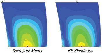
The number of reports dealing with the application of surrogate modelling in turbomachinery engineering indicates increasing interest from both industry and academia. Recent work(Reference Bunell, Thelin, Gorell, Salmon, Ruoti and Hepworth8-Reference Walther and Nadarajah12) utilised this technique to predict structural responses from finite element analysis. In 2017, for instance, Zhang et al.(Reference Zhang, Guo, Li, Yang and Yue9) and Geller et al.(Reference Geller, Schemmann and Kluck10) explored and optimised the design of various turbomachinery engine components. Concentrating on the maximum stress as a single structural value that can be rapidly emulated by a surrogate model, the geometries considered were a turbine disk(Reference Zhang, Guo, Li, Yang and Yue9) and compressor impellers(Reference Geller, Schemmann and Kluck10). Both publications mentioned an accurate estimation at negligible computational cost in comparison with finite element simulation results. Furthermore, Heap et al.(Reference Heap, Hepworth and Jensen11) and Walther et al.(Reference Walther and Nadarajah12) derived innovative methods for the expansion from single- towards multi-value result prediction. By representing the stress at each node by a unique surrogate model, Heap et al.(Reference Heap, Hepworth and Jensen11) found that the entire stress distribution can be predicted. Concurrently, this method required that the nodes of the mesh structure specified for reconstruction of the FE result via surrogate models shared an identical relative position across each of the FE models used during training. The use of a parametric mesh limited that study to simple parts. Next, Walther et al.(Reference Walther and Nadarajah12) reported that surrogate models permit accurate predictions of nodal locations of very complex geometries. Instead of setting up a parametric mesh, as done by Heap et al.(Reference Heap, Hepworth and Jensen11), mesh morphing was applied. This meshing strategy enabled Walther et al.(Reference Walther and Nadarajah12) to predict more complex geometries. In 2018, Bunnel et al.(Reference Bunell, Thelin, Gorell, Salmon, Ruoti and Hepworth8) combined the possibilities identified by Heap et al.(Reference Heap, Hepworth and Jensen11) and Walther et al.(Reference Walther and Nadarajah12), developing a method for the reproduction of the entire stress distribution and geometric shape of turbomachinery engine components. Thus, each nodal stress value and position was emulated using a unique surrogate model. By means of mesh morphing, the requirement for an identical FE model mesh structure was satisfied. An essential motivation was to perform DSE on compressor blades, seeking to understand their full structural response across different parametric combinations. For visualisation, Fig. 2 compares the von Mises stress distribution at the suction side of a compressor blade calculated via surrogate models versus FE simulation. The colour scale is matched. X indicates the maximum stress position, and O the minimum stress position. Referring to Bunnel et al.(Reference Bunell, Thelin, Gorell, Salmon, Ruoti and Hepworth8), the FE results and surrogate model predictions exhibited comparable geometric shape, and stress distributions and magnitudes. The reconstruction of the FE result via the surrogate models correctly predicted a region of high stress located at the root of the blade at the middle of the chord. Less than  $5\% $ error was achieved on all the tested blades.
The procedure applied for surrogate model generation in this work is illustrated in Fig. 3. Following the definition of the variable design parameters, the Monte Carlo sampling method is chosen for extensive database creation. It relies on random sampling to explore the design space. Full factorial, fractional factorial and basic Latin hypercube are well-known alternative sampling methods, but are not recommended in literature(Reference Zimmermann and Krischer13). Next, FE models of the new design parameter combinations obtained from the Monte Carlo sampling method were set up and solved using the commercial Abaqus FEA software. Evaluation of the simulation results at specified nodes supplied the database with response values for given sets of design parameter combinations. Provisionally, Gaussian process regression was selected as the algorithm for generating the surrogate models. The Gaussian process regression is also known in the geostatistics field as kriging, representing a non-parametric kernel-based probabilistic approach that is widely used in applied mathematics, statistics and machine learning for constructing surrogate models(Reference Zimmermann and Krischer13-Reference Yang, Tartakovsky and Tartakovsky15). Trained on the information stored in the database, the resulting surrogate models allow for rapid predictions of the results for new design parameter combinations. This procedure was automated using the commercial software MATLAB by MathWorks.
von Mises stress distributions on the suction side of a compressor blade published by Bunnel et al.(Reference Bunell, Thelin, Gorell, Salmon, Ruoti and Hepworth8).

Procedure for surrogate model generation.

The implementation of alternative options for surrogate model algorithms should be tested in future investigations, with a focus on training time, robustness, predictive speed and accuracy. According to literature(Reference Bunell, Thelin, Gorell, Salmon, Ruoti and Hepworth8,Reference Jin, Chen and Simpson16) , the radial basis function is considered to be the most reliable method in terms of accuracy and robustness, performing well with sparse training data in design spaces that include many parameters. In contrast, the first studies applied to the case presented herein demonstrated much better results in terms of accuracy and time consumption when implementing the Gaussian process regression. A brief summary of selected surrogate model algorithms extracted from literature(Reference Bunell, Thelin, Gorell, Salmon, Ruoti and Hepworth8,Reference Zimmermann and Krischer13,Reference Rasmussen and Williams14,Reference Jin, Chen and Simpson16,17) is given in Annex B.
3.0. COMPRESSOR CASING DESIGN
Traditionally, designs of compressor casings are highly coupled to the technology available at the time of design, depending on technology-determining characteristics such as the materials used or the manufacturing methods applied. Bretschneider et al.(Reference Bretschneider, Rothe, Rose and Staudacher18) identified a high level of similarity among compressor casing designs disclosed by aero-engine manufacturers. This tendency is a direct consequence of the use of engine family concepts based on similar, scaled or further developed high-pressure systems with high commonality, driven by saving development costs and simultaneously implementing mature, successfully marketed component technologies(Reference Bretschneider, Rothe, Rose and Staudacher18).
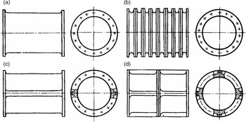
In practice, mixed architectures between the four types of axial compressor casing design illustrated in Fig. 4 are prevalent. Most current aero-engine axial compressor casings feature an axial split in the front stages and change to a combination of double-walled ring style in the rear section. The axial split casing design provides the required access for assembling variable stator vanes and the corresponding actuation mechanism. The radial split casing is preferred when short local casing elements are preferred per stage. Well-defined axial load transmission linked with the provision of a very high casing stiffness is one of the main roles of the double-walled casing design, besides the accommodation of bleed air off-take in different stages. Frequently, the inner casing wall is thermally designed to allow tip clearance optimisation in stages where rotor blades are physically small and the stage efficiency is very sensitive to changes in tip clearance.(Reference Bretschneider, Rothe, Rose and Staudacher18)
General types of axial compressor casings(Reference Bretschneider, Rothe, Rose and Staudacher18,19) : (a) integral case, (b) radial split case, (c) axial split case and (d) double-walled case.

For reasons of detailed categorisation, literature(Reference Bretschneider, Rothe, Rose and Staudacher18) differentiates between mid-rotor split and inter-stage flange designs as derived sub-elements. The mid-rotor split flange design is characterised by splitting the casing above the rotor and offers advantages in terms of stiffness as well as blade-loss containment ability. The concept of the inter-stage flange design extends over a full stage, covering a stator and a rotor (or vice versa). Thus, it incorporates the rub-in liner for rotor blades as well as the T-Slot mount for stator vanes. A mix between both casing flange design shapes is possible but rarely found in existing aero-engine arrangements.(Reference Bretschneider, Rothe, Rose and Staudacher18)
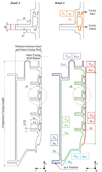
High-pressure compressor casing geometry (left) and schematic of the boundary and load conditions implemented for the compressor casing assembly (right).

4.0. MODEL SETUP
This section describes the 2D axisymmetric FE model setup for the multi-stage high-pressure axial compressor casing assembly conceived for training database generation. Figure 5 visualises the main architecture and a schematic of the boundary and load conditions implemented. Created with reference to the rear section of the general arrangement illustrated in Fig. 1, it represents a double-walled casing construction, combining radial split as well as inter-stage flange designs. With respect to future work involving the extension of a given casing arrangement, a standardised component design process was established to allow the addition of more casing rings and stators. Detail A defines the geometric parameters (height  $H$, width
 $W$ and positioning
 $P$) selected for the modification of each flange within the ranges listed in Table 1, and the red-coloured arrows indicate the corresponding directions of geometry variation. To avoid unfeasible geometry modifications, linear inequality constraints must be imposed between the flange widths and positions. If not other specified, the flange dimensions used in the figures of this section correspond to the default values listed in Table 1.
Using the commercial Abaqus FEA software, coupled thermo-mechanical implicit simulations were carried out. As mentioned above, Fig. 5 graphically summarises the boundary and load conditions implemented, as well. Index  $a$ describes the outer side of the casing, index
 $i$ the inner side of the casing exposed to the compressed core flow and index
 $m$ the surface of the inner casing structures wetted with bleed air. Considering leakage, index
 $c$ characterises those surfaces that are in contact with the stator cavity leakage flow driven by the pressure gradient across the stator row. Index
 $p$ designates the peripheral surfaces of the model. T symbolises the temperature, p the pressure and
 $\alpha$ the heat transfer coefficient. The corresponding set of parameter values used are presented in Table 2. Regarding the definition of contacts between the components included in the casing assembly, the implementation was configured consistently with previous work(Reference Schmidt, Gümmer and Konle4-Reference Schmidt, Hupfer, Gümmer and Konle6). For the heat transfer analysis, tie constraints were introduced, and their subsequent substitution by surface-to-surface contact interactions permitted thermo-mechanical analysis with allowed part separation. Moreover, an additional fixation is installed to lock the degree of freedom in the
 $\varphi $–
 $z$ direction.
Provisional material selection for the complete casing assembly resulted in high-temperature-resistant Inconel 718. The isotropic material model implemented contains temperature-dependent data for the Young’s modulus, Poisson’s ratio, density, specific heat capacity, thermal expansion coefficient and thermal heat conductance, sourced from refs. (20-22). Validation attempts confirmed the correct reproduction of the material characteristics, while an upgrade to a multi-material definition will be part of future work.
Geometric flange parameter variation

The parameter settings presented in Table 2 are considered to be steady state. They first define the case for an unloaded structure (initial condition). The subsequent initial load condition represents the load setting resulting from operation at the design point of a modern high-pressure compressor. The core flow pressure  ${p_{i,I}}$ and temperature
 ${T_{i,I}}$ were defined as
 $z$-dependent functions, both increasing linearly in the flow direction. Compared with
 ${p_{i,I}}$ and
 ${T_{i,I}}$, the transition to
 ${T_{i,II}}$ and
 ${p_{i,II}}$ constitutes the end of the compression induced by the rotor. Consequently,
 ${T_{i,II}}$ and
 ${p_{i,II}}$ remain constant. In accordance with previous work(Reference Schmidt, Gümmer and Konle5,Reference Schmidt, Hupfer, Gümmer and Konle6) , even pressure-gradient-driven leakage flows through the stator cavities were considered via
 ${T_c}$ and
 ${p_c}$. The corresponding pressure compensations from the cavity inlets towards their outlets were configured by setting
 ${p_c}$ equal to the expression used for
 ${p_{i,I}}$. Constant values calculated for
 ${T_{i,I}}$ at the respective
 $z$-positions of the cavity inlets were taken for
 ${T_c}$.
Parameter settings applied on the surfaces of the generic high-pressure compressor casing structure

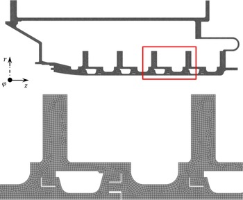
As an example of the hybrid computational grids generated and used in this work, Fig. 6 shows the mesh of the 2D axisymmetric FE model of the compressor casing assembly for the case using the default flange dimensions. It consists of approximately 12,800 second-order elements, and the mesh resolution is capable of providing smooth and converged computational solutions. Moreover, attention was paid to each contact surface to ensure node-to-node matching between the part instances involved. The area within the red frame shows a magnified detailed view of the meshed geometry.
Generated mesh of the 2D axisymmetric high-pressure compressor casing assembly with detail view.

Measurement sites selected for FE simulation result evaluation.

The expansion behaviour of the inner casing surface during engine operation is particularly relevant for an adequate tip clearance assessment. With a focus on the radial casing displacement, the measurement sites coloured in red and displayed in Fig. 7 were considered for to evaluate the FE simulation and supplement the training data. R represents the centre position immediately above the rotor blades, and S the centre position of the stator vane shrouds. In this way, the resulting tip clearance formed by the rotor blade tips and the compressor casing can be calculated at the measurement sites R1, R2, R3, R4 and R5. Meanwhile, the clearances described by the vane tips radially inboard of the stator vanes and the rotor drum will be calculated at the measurement sites S1, S2, S3 and S4.
5.0. RESULTS AND DISCUSSION
Referring to Fig. 3, the database generated for this work covered the evaluation of 1,000 FE simulation results and stored 21 variables per FE simulation. For categorisation,  $12$ variables involving the geometric parameter data
 $H$,
 $W$ and
 $P$ of four flanges were linked with one variable per measurement site, containing data for the radial casing displacement. In total, this required the training of nine surrogate models.
5.1 Computational cost
A summary of the elapsed times for the complete procedure with reference to Fig. 3 is presented in Table 3. The option of distributing the FE simulations simultaneously between multiple computers and later combining the results would allow for even faster database generation than listed. Another correlation detected and shown in Fig. 8 is the increase in the time required to train all nine surrogate models when an increasing amount of data is stored. Due to the exponential scaling, the time required is considerable for even larger databases. Temporarily, the Gaussian process regression is responsible for this fact, and future work will include a comparison with alternative algorithms. Once the process of training the surrogate models is finished, there is no need for repetition unless the database is complemented. Compared with an individual high-fidelity FE simulation, the reductions attained in computational time for the prediction of new design parameter combinations amount to  $99.9\% $ in favor of the surrogate models.
5.2 Validation and precision
For validation of the results predicted by the surrogate models, a verification database was generated. In total, it stored the FE simulation results calculated from  $50$ different model setups with various flange parameter sets randomly selected by means of the Monte Carlo sampling method. After feeding in the equivalent parameter sets, the responses in the radial displacement received from the surrogate models were compared with the FE results saved in the database for verification. The precision of the surrogate models was evaluated by determining the mean
 $\mu $ and standard deviation
 $\sigma $ for the complete set of verification cases. Both
 $\;\mu $ and
 $\sigma $ were used to determine the type of distribution exhibited by the errors in the prediction results. In case of a normal distribution, the
 $\mu \pm \sigma $ range would contain approximately
 $68.3\% $ of the calculated values, while for the
 $\mu \pm 2\sigma $ range this percentage would increase to approximately
 $95.4\% $. Annex A visualises the histograms of both the dimensional and percentage error in the radial displacement result predictions, determined for each measurement site. The mean
 $\mu $ as well as the
 $\mu \pm \sigma $ and
 $\mu \pm 2\sigma $ ranges are labelled, and Table 4 presents the percentage of the predicted values within each range. Compared with the normal distribution, the number of cases within the confidence range was largely similar or even higher. In total, more than
 $90\% $ of the verification cases were predicted correctly within the
 $\mu \pm 2\sigma $ range.
Elapsed times for the individual processes in surrogate model generation calculated with an Intel® Core™ i7-6700 3.4-GHz quad-core processor

Considering the complete set of measurement sites, the dependence of the precision of the results predicted via the surrogate models based on the information stored in the training database is illustrated in Fig. 9. Starting with a  $\mu \pm 2\sigma $ standard deviation range of
 $ \pm 0.2{\rm{mm}}$, the precision in reproducing the radial displacement improved significantly with each supplementation until the database contained the simulation results of
 $100$ cases. As shown in the magnified section, only slight improvements were seen when increasing the size of the database from
 $200$ to
 $1000$ cases. Precisions down to the range of manufacturing tolerances were achieved.
Percentage error in radial displacement prediction within the considered confidence ranges  $\mu \pm \sigma $ and
 $\mu \pm 2\sigma $ at the specified measurement sites

Evolution of the elapsed time for training the surrogate models with growing database size.

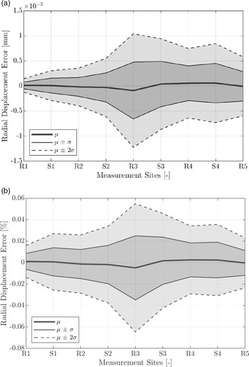
To complete this validation and precision section, the diagrams in Fig. 10 show the statistical results for the dimensional and percentage error range for the radial displacement predicted by the surrogate models based on the measurement sites. The results are based on a training dataset of  $,1000$ FE simulation results. A precise tendency of the mean value
 $\mu $ towards negative or positive values is not detected, and when approaching measurement site R3, the standard deviation
 $\sigma $ tends to reach peak values. The majority of the statistical errors, which fall inside the
 $\mu \pm 2\sigma $ range, are still in the micrometre range, or below
 $0.07\% $ in terms of the corresponding radial casing displacement values. Nevertheless, for a different verification dataset, the estimated mean
 $\mu $ and standard deviation
 $\sigma $ values are expected to slightly change.
5.3. Parametric optimisation
Dependence of precision in result reproduction on training database size.

Statistical error ranges in radial displacement prediction at the specified measurement sites: (a) dimensional and (b) percentage error.

The potential of surrogate models increases when they are linked with extensive DSE and optimisation algorithms. So far, the surrogate models generated for the present work have been proven to deliver highly precise radial displacement predictions. This section covers the inclusion of surrogate models to derive an optimum  $H$,
 $P$,
 $W$ parameter set for achieving a specific radial casing displacement and minimising the tip clearance. For reasons of consistency with the previous sections, the height
 $H$, positioning
 $P$ and width
 $W$ of four flanges were used as the design variables here too. The minimum and maximum values presented in Table 1 describe the constraints on the design variables selected for this parametric optimisation. Additional linear inequality constraints were imposed between the flange widths and positions to avoid unfeasible geometry modifications. Total tip clearance minimisation was implemented as a single-objective optimisation problem. During the optimisation process, the surrogate models were used to rapidly evaluate the radial casing displacements at the specified measurement sites. Furthermore, a provisional rotor expansion was set for each measurement site. Consequently, the tip clearances were calculated as the difference in the radial displacement between the casing and rotor. Subsequent summation returned the total tip clearance value, which was to be minimised. For the stopping criterion of the optimisation process, a constraint tolerance of 5 × 10⁻⁵mm was considered sufficient, given that the error related to the surrogate models is even larger than this tolerance. Table 5 provides an insight into the main results. To enable a simple categorisation, global as well as local optimisation algorithms already defined in MATLAB were tested, coupled and compared. In general, all the local optimisation algorithms provide input-data-dependent solutions for non-linear or non-convex problems. Thus, beginning with a global parameter optimisation and feeding the received dataset into the subsequent local optimisation allows an identification of the best solution within the complete design space. In case of local optimisation, the active set as well as interior point algorithms were implemented. The genetic algorithm provided by MATLAB was used for global optimisation.
Results of the tip clearance optimisation

Referring to Table 5, the key aspects that emerge from the analysis of these results is the ability for tip clearance minimisation, the corresponding flange weight difference and the elapsed time. With respect to the first of these, setting an initial global and subsequent local optimisation definitely returns the preferable parameter sets and total tip clearance values within an acceptable additional time expense. When considering the weight as well, a trade-off must be solved. In the present case, the active set algorithm performed slightly better in terms of meeting the objective of tip clearance minimisation. In contrast, the interior point algorithm identified thea configuration leading to a lighter-weight design.
A summary of the optimum  $H$,
 $W$ and
 $P$ parameter values obtained from the tip clearance minimisation is shown in Fig. 11. The solid curves denote the flange dimensions obtained from the global genetic optimisation. The dashed (active set) and dotted (interior point) curves characterise the results achieved from the subsequent local optimisation using the global optimised parameter set as input data. When comparing the dimensional development of the additionally local optimised
 $H$,
 $W$ and
 $P$ parameter sets from the first to last flange of the multi-stage compressor casing, predominantly good agreement can be observed. In contrast, a dimensional match with the parameter configuration proposed by the genetic algorithm rarely occurs. For the sake of completeness, Fig. 12 presents the resulting compressor casing geometries identified via the coupled global–local optimisation.
Optimised flange parameter sets for tip clearance minimisation.

Optimised compressor casing geometries: (a) genetic–active set, (b) genetic–interior point.

In this work, it is assumed that the rotor expansion data already exist. The rotor data can be derived either from a separate rotor model simultaneously calculated with the casing or from previous designs that are available; For instance, the option of reusing data from a previous aero-engine compressor design appears attractive when only an existing casing construction is retrofit or modified while the rotor assembly remains unchanged. The casing modification may include measures for active clearance control or other equivalent technologies that are identified.
6.0. CONCLUSIONS AND PROSPECTS
The present work explored the potential of surrogate modelling in FE-based preliminary compressor casing design. The key aspects of the evaluation mainly concentrated on the capability to perform rapid tip clearance assessments and the precision of the reproduction of the FE results for the radial displacements. For this purpose, a 2D axisymmetric steady-state FE model of a generic multi-stage high-pressure axial compressor casing available from previous work(Reference Schmidt, Hupfer, Gümmer and Konle6) was re-used. Modification of the geometric flange design parameters ( $H$,
 $W$ and
 $P$) via the Monte Carlo sampling method was used for FE data generation and DSE. The Gaussian process regression was chosen as the algorithm to generate the surrogate models trained on the datasets received from DSE and stored in a dedicated database.
In this investigation, once the surrogate models had been trained, the time required for the surrogate model prediction and full FE computations could be compared immediately. After the training process, DSE and database generation emerged as the most time-consuming tasks of the overall procedure in creating the surrogate models.
Statistical methods were applied to validate the accuracy of the surrogate models in terms of reproducing the FE results. Depending on the size of the database, precisions down to the range of manufacturing tolerances were achieved.
On the basis of these successful results, the surrogate models were included in an optimisation process to determine an optimised  $H$,
 $W$ and
 $P$ parameter set for tip clearance minimisation. Coupling global with local optimisation algorithms achieved the most promising results.
Overall, surrogate modelling can contribute to better understanding of design problems across different parametric combinations(Reference Bunell, Thelin, Gorell, Salmon, Ruoti and Hepworth8). The fact that such trained surrogate models are computationally inexpensive in comparison with numerical FE simulations makes them attractive for inclusion in parametric optimisations. The prediction error related to the surrogate models depends on the number of training samples as well as the number and type of parameters emulated(Reference Bunell, Thelin, Gorell, Salmon, Ruoti and Hepworth8). Also, the time required to train the surrogate models is affected by the magnitude and quality (noise on the data) of the training database(Reference Jin, Chen and Simpson16) as well as by the algorithm used to construct the surrogate model(Reference Bunell, Thelin, Gorell, Salmon, Ruoti and Hepworth8). An additional phenomenon affecting the prediction error and training time is the tendency of specific surrogate model algorithms to become overfit, resulting in increasing irregularity and larger local errors(Reference Zimmermann and Krischer13).
Future work related to the present project will cover the implementation of additional optional features in the database generation process. Specifically, work on the selection of the flange design, the number of compressor stages, the material combination of the casing assembly and the load conditions applied (transient or steady state) is being planned. Moreover, alternative sampling methods as well as surrogate model algorithms have potential for ongoing parameter studies.
To capture the transient nature of tip clearances during engine operation, modifications of the procedure presented herein will be required primarily in the database generation and evaluation processes. For a brief classification, steady-state FE simulations only return results for a single parameter set relevant to the evaluation. When performing transient FE simulations for database generation, the results could be evaluated for several time-resolved parameter sets. For each time increment considered and each measurement site evaluated, a unique surrogate model can then be generated. Considering tip clearance minimisation based on optimisation of the geometric parameters of the compressor casing, the only relevant time increments are those representing the pinch points where the minimum tip clearances occur during transient engine operation. To avoid unnecessary expense, it is advisable to concentrate the evaluation on the results of transient FE simulations only at relevant time increments and to proceed with surrogate model generation as presented herein. Additional techniques for further improving the tip clearances during transient engine operation would involve active control approaches.
ANNEX A
Figure A1.

Figure A1.

ANNEX B
Summary of selected surrogate model algorithms extracted from literature

If not specifically cited, the information in Annex B refers to ref. (Reference Zimmermann and Krischer13).
 (engl.: Develop-ment and Design of Aero Engines),
 ,