
Size effects in plasticity at small length scales have been demonstrated through different experiments, some by imposing a strain gradient,[ Reference Fleck, Muller, Ashby and Hutchinson 1 – Reference Stolken and Evans 3 ] others by changing the external sample size.[ Reference Uchic, Dimiduk, Florando and Nix 4 , Reference Uchic, Shade and Dimiduk 5 ] Simple shear of a thin-layer sandwiched between and well-bonded to two non-deforming substrates has been studied theoretically in the development of both strain gradient plasticity (SGP) and discrete dislocation plasticity.[ Reference Fleck and Hutchinson 6 , Reference Shu, Fleck, Van der Giessen and Needleman 7 ] Normal compression of a thin-layer bonded between rigid platens has offered another theoretical case study for SGP.[ Reference Niordson and Hutchinson 8 ] While such confined deformation geometries offer easy configurations for calculation within various plasticity models, experimental studies relevant to plastic deformation of confined thin layers have lagged behind theoretical developments. A previous experiment attempted to load thin Al layers diffusion bonded between Al2O3 adherents in shear.[ Reference Tagarielli and Fleck 9 ] With the Al layer thickness ranged between 10 and 50 µm, that experiment found no conclusive evidence of a dependence of strength on the Al layer thickness.[ Reference Tagarielli and Fleck 9 ]
We recently demonstrated a new experimental protocol for evaluating the plastic flow response of metal thin films confined between two elastic–brittle solids.[ Reference Mu, Hutchinson and Meng 10 ] Metal thin films are vapor deposited onto a ceramic substrate, followed by vapor deposition of another ceramic top layer. Such a ceramic/metal/ceramic sandwich structure is then fabricated via scripted focused ion beam (FIB) milling into microscale cylindrical pillars, between 2 and 5 µm in diameter. Axial compression loading on the ceramic/metal/ceramic micro-pillar then affects different kinds of loading on the metal film layer, depending on the orientation of the metal film with respect to the pillar axis. In the case of CrN/Cu/Si micro-pillars, axial compression led to extensive plastic deformation of Cu films in both confined shear and confined normal compression, when the Cu layers were oriented respectively at 45° and 90° with respect to the pillar axis.[ Reference Mu, Hutchinson and Meng 10 ] Measured flow stresses of Cu films in confined shear and normal compression showed a strong dependence on the film thickness: increasing by more than a factor of 2 as the film thickness decreased from ~1200 to ~150 nm, exhibiting significant mechanical size effects.[ Reference Mu, Hutchinson and Meng 10 , Reference Mu, Chen and Meng 11 ]
Mechanisms responsible for the dependence of confined plastic flow stresses on Cu film thickness remain to be further studied. Two prominent factors to be considered are the role played by the presence of an imposed strain gradient and the influence of the Cu microstructure. In confined plastic flow configurations, the presence of interfaces between the deforming Cu layer and the non-deforming Si and CrN layers leads to increasing strain gradients within Cu with decreasing Cu layer thickness, and consequently to increases in flow stress as the Cu film thickness decreases.[ Reference Fleck and Hutchinson 6 – Reference Niordson and Hutchinson 8 ] Previous observations of the dependence of strength of monolithic micro-pillars on diameter[ Reference Uchic, Dimiduk, Florando and Nix 4 , Reference Uchic, Shade and Dimiduk 5 ] were rationalized by the influence of pillar size on dislocation processes, in particular the balance between dislocation multiplication and annihilation.[ Reference Greer, Oliver and Nix 12 ] The role film microstructure plays in the present confined plastic flow experiments is therefore of interest as well. In this paper, we report response of sputter-deposited polycrystalline Cu thin films in confined plastic flow when changes are made to the Cu microstructure.
Axial compression testing was conducted on micro-pillars fabricated by scripted FIB milling.[ Reference Mu, Hutchinson and Meng 10 , Reference Mu, Chen and Meng 11 ] The pillar diameter, D, in all experiments was ~5 µm. Pillar compression was made with a custom, ~10 × ~10 µm, flat-ended diamond punch on a NanoIndenter XP instrument. An increasing axial load was applied to the pillar top surface in a displacement-controlled mode. An indenter displacement rate of 5 nm/s was specified, with the raw indenter load L and the total indenter displacement d monitored continuously. Loading was stopped when a specified d was reached, followed by load removal.
Sputter depositions of polycrystalline Cu and CrN thin films onto Si(100) substrates were conducted in an inductively coupled plasma (ICP)-assisted magnetron sputtering system.[ Reference Meng, Curtis, Rehn and Baldo 13 ] All depositions occurred without intentional substrate heating. A brief Ar ICP etch was applied to all Si(100) substrates before deposition began. In one specimen series, a polycrystalline Cu film was sputter deposited in an Ar ICP directly onto etched Si(100) substrates, followed immediately by reactive sputter deposition of a CrN top layer in an Ar/N2 ICP, forming a CrN/Cu/Si sandwich structure. In another specimen series, a thin CrN buffer layer, ~55 nm in thickness, was first deposited onto etched Si(100) substrate, followed by sequential depositions of a Cu film and a CrN top layer, forming a CrN/Cu/CrN/Si(100) sandwich structure. These two specimen series were made with various Cu film thicknesses, h. In all cases, the top CrN layer is polycrystalline, has a thickness exceeding 5 µm and a pronounced columnar structure. For microstructural analysis purposes, additional specimens in configurations of Cu/Si(100), buffered Cu/CrN/Si(100), and CrN/Cu/CrN/Si(100) in which both CrN layers are ~50 nm in thickness were deposited. Further details on film deposition have been described elsewhere.[ Reference Mu, Chen and Meng 11 ] Composition analysis by x-ray photoelectron spectroscopy (XPS) on sputtered Cu and CrN films showed oxygen and carbon contamination levels below the instrumental detection limit of ~1 at.%, and that the CrN films had N:Cr ratios close to 1:1.[ Reference Mu, Chen and Meng 11 ]
Structural characterizations on Cu and CrN films were conducted by x-ray diffraction (XRD) and transmission electron microscopy (TEM). A PANalytical Empyrean system with Cu K α radiation was used for XRD measurements in the symmetric θ–2θ, glancing incidence diffraction with a fixed incidence angle ω, and pole figure geometries. Specimens for TEM studies were extracted following standard site-selective lift-out procedures using a FEI Quanta3D FEG e −/Ga+ dual-beam FIB instrument equipped with an OmniProbe. Final thinning/cleaning of lift-out specimens to electron transparency was carried out with Ar+ ions at 100 eV using a Gatan PIPS II Precision Ion Polishing System. TEM examinations were conducted on a JEOL JEM2010 instrument operated at 200 kV. Additional scanning microscopy with electron-induced or ion-induced secondary electrons (SE/ISE) was conducted on the FIB instrument.
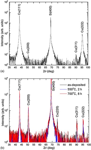
Figure 1 shows typical θ–2θ XRD results obtained from Cu/Si(100) and Cu/CrN/Si(100) specimens. Excluding the Si(400) substrate reflection, all peaks are indexed to a face-center cubic (fcc) structure with a lattice parameter of 3.614 Å, close to the bulk Cu lattice parameter of 3.615 Å. Figure 1(a) shows that Cu films deposited directly onto ICP-etched Si(100) substrates exhibit almost complete alignment of Cu〈111〉 with the Si[100] growth direction. Additional ω rocking curve measurements show that the Cu〈111〉 mosaic spread ranges from ~2° to ~4° and increases as the Cu film thickness h decreases. Separate Cu〈111〉 pole figure measurements show random in-plane orientation, consistent with these Cu films having a random fiber texture with Cu〈111〉//Si[100]. Figure 1(b) shows that Cu films deposited onto the thin CrN buffer layer possess significantly different textures as compared with those deposited directly onto ICP-etched Si(100). In this case, major crystallographic directions of Cu〈100〉, Cu〈110〉, and Cu〈111〉 are all present along the Si[001] growth direction, suggesting a much more random crystallographic orientation distribution. Data in Fig. 1(b) further show that extended annealing at 550 and 700 °C, up to 8 h, does not appear to further change the Cu orientation distribution in a significant way. Due to the presence of the CrN buffer layer, no evidence of extraneous phase formation involving Cu is observed from XRD after extended annealing. Diffraction results obtained from CrN/Cu/CrN/Si(100) specimens, in which both the CrN buffer layer and top layer are ~50 nm in thickness, are similar to those shown in Fig. 1(b).
θ–2θ XRD patterns from as-deposited and annealed Cu films: (a) from an as-deposited Cu/Si(100) specimen; (b) from a Cu/CrN/Si(100) specimen in the as-deposited state and after annealing at 550 and 700 °C.

Microstructural characteristics of as-deposited and annealed Cu films are illustrated by the TEM images shown in Fig. 2. Figure 2(a) shows a typical cross-sectional bright-field (BF) image from one as-deposited CrN/Cu/Si(100) specimen, with the CrN top layer not shown. The Cu layer consists of a mixture of near equi-axed grains and columnar grains with large height-to-width ratios. Typical columnar Cu grains are ~60 nm in width, with multiple internal twin lamella of ~10 nm in thickness. Similar Cu grain structures were observed from as-deposited CrN/Cu/CrN/Si(100) specimens. Figure 2(b) shows a typical cross-sectional BF image from one CrN/Cu/CrN/Si(100) specimen, annealed at 550 °C for 4 h. The thickness of the CrN buffer layer is ~55 nm, and only a portion of the top CrN layer is shown. The CrN/Cu and Cu/CrN interfaces appear clean, with no evidence of reaction with Cu due to annealing. The Cu layer again consists of a mixture of near equi-axed and columnar grains. Large columnar Cu grains are over 200 nm in width, with internal twin lamella of >25 nm in thickness. In addition to such evidence of grain growth, the annealing appears to increase the inhomogeneity of the Cu grains: some Cu columns are ~400 nm in height and occupy a substantial fraction of the Cu layer thickness, while other Cu grains remain significantly smaller and more equi-axed in morphology. Similar microstructural characteristics are observed for CrN/Cu/CrN/Si(100) specimens annealed at 550 °C for 12 h, in terms of increased Cu column widths, increased twin lamella thickness, and increased Cu grain inhomogeneity.
Typical TEM images of Cu films: (a) BF of an as-deposited CrN/Cu/Si(100) specimen; (b) BF of a CrN/Cu/CrN/Si(100) specimen annealed at 550 °C for 4 h. Both images were taken in the Si〈110〉 zone axis orientation, with interfaces parallel to the electron beam. Dashed lines point to interfaces and various boundaries between Cu grains.

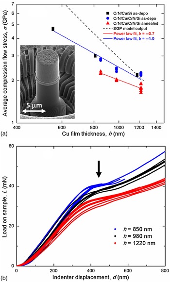
Micro-pillars with D ~ 5 µm were fabricated out of CrN/Cu/Si(100) specimens in the as-deposited state, and out of CrN/Cu/CrN/Si(100) specimens in the as-deposited state as well as after annealing at 550 °C for 4 h. Figure 3(a) summarizes the results of axial compression testing on pillars with their axes perpendicular to the confined Cu layers (90° oriented interfaces). As shown in Fig. 3(b) and reported previously,[ Reference Mu, Hutchinson and Meng 10 ] an intermediate load plateau is observed in all raw load versus indenter displacement, L–d, curves, the appearance of which marks the initiation of plastic deformation of the confined Cu layer. The inset in Fig. 3(a) shows the typical morphology of plastic deformation of Cu: starting at the plateau load, the Cu layer is being squeezed out at the perimeter of the layer. The average compression flow stress is evaluated from the intermediate plateau load, σ = L/(πD 2/4). Values of σ measured from CrN/Cu/Si(100) pillars in the as-deposited state are in good agreement with those measured from CrN/Cu/CrN/Si(100) pillars in the as-deposited state. That is, the two sets of σ values are consistent with each other in magnitude and exhibit one consistent dependence on the Cu layer thickness h. Figure 3(a) shows that this σ−h dependence, combining these two data sets obtained from Cu films in the as-deposited states, appears to follow a power-law relationship, σ = ahb , with a fitted power-law exponent of b ~ −1.0. One should note that the shear test for the films oriented at 45° has essentially no dependence on the pillar diameter whether gradients come into play or in the limit of conventional plasticity. By contrast, the normal compression test involves a fairly strong dependence on the ratio of film thickness to pillar diameter even in conventional plasticity. Thus, for the normal compression test, the relationship σ = ahb reflects both test geometry and material size dependence. It is also important to note that the stress state in the film in the normal compression test is not uniaxial compression—it is a superposition of uniaxial compression, hydrostatic pressure, and shear which vary radially from the center of the specimen outward to the edge. For material to be extruded, given the film is bonded to the substrates, the sign of the shear stress must be different in the upper half of the film from the lower half. The most basic SGP model has been used to compute the dependence on the film thickness in Fig. 3(a).[ Reference Mu, Hutchinson and Meng 10 ] The model imposes zero plastic strain at the film/substrate interfaces thereby modeling blockage of dislocations as they approach the substrate interfaces. The ring of extruded material at the outer rim of the film is not accounted for in the numerical model simulation. A simple estimate of the effect suggests that it should have a small influence on the load in the normal compression test.
Axial compression testing on pillars with 90° oriented interfaces: (a) average compression flow stress measured through axial compression on pillars with 90° oriented interfaces. The inset shows a typical morphology for deformation of confined Cu layers in normal compression; (b) raw L–d curves obtained from CrN/Cu/CrN/Si(100) pillars annealed at 550 °C for 4 h. The arrow indicates the approximate location of the intermediate load plateau. The dashed line in (a) represents the SGP model output.

Data shown in Fig. 3 indicate that changes in the orientation distribution of Cu grains in as-deposited Cu films, due to the absence or presence of the CrN buffer layer, do not appear to significantly influence the confined plastic flow of Cu in the normal compression geometry. The annealing at 550 °C for 4 h, however, brings significant changes to measured σ values. At the same Cu layer thickness, annealing led to a ~20% decrease in σ. Furthermore, the annealing appears to alter the dependence of σ on h: while the σ−h dependence continues to follow a power-law relationship, the fitted power-law exponent is now b ~ −0.7, although this difference is made less certain by the large scatter in the original data points and therefore increased uncertainty in the fitted b value.
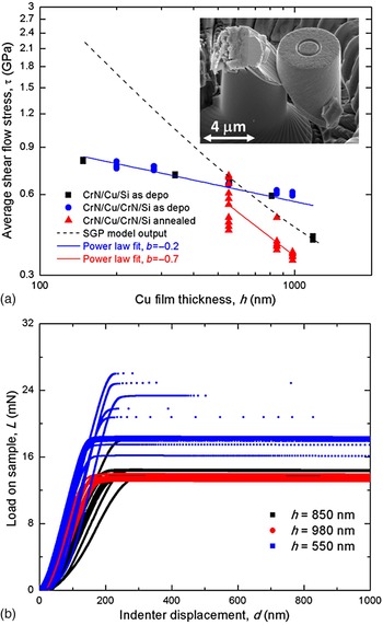
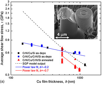
Figure 4 summarizes the results of axial compression testing on pillars with the confined Cu layers oriented at 45° with respect to the pillar axes (45° oriented interfaces). Again, micro-pillars with D ~ 5 µm were fabricated out of CrN/Cu/Si(100) specimens in the as-deposited state, and out of CrN/Cu/CrN/Si(100) specimens in the as-deposited state as well as after annealing at 550 °C for 4 h. Figure 4(a) summarizes the testing results. As reported previously, an extended load plateau, shown in Fig. 4(b), is observed after an initial steep rise in load, the appearance of which is linked to shear plastic deformation of the confined Cu layer.[ Reference Mu, Hutchinson and Meng 10 , Reference Mu, Chen and Meng 11 ] This extended load plateau is followed by an eventual large indenter displacement excursion, which signifies a catastrophic shear failure in the confined Cu layer. The inset in Fig. 4(a) shows the typical morphology of final pillar failure in shear.[ Reference Mu, Hutchinson and Meng 10 , Reference Mu, Chen and Meng 11 ] The average shear flow stress of the confined Cu film is evaluated from the plateau load, τ = L/(πD 2/4)/2. An attractive feature of the shear test is that the layer experiences this shear stress independent of the pillar diameter, apart from a very small deviation at the free edge of the film. Again, pillars with 45° oriented interfaces fabricated from CrN/Cu/Si(100) and CrN/Cu/CrN/Si(100) specimens in the as-deposited state are in good agreement. As shown in Fig. 4(a), the observed τ−h dependence for as-deposited specimens appears to follow a single power-law relationship, τ = ahb , with a fitted power-law exponent of b ~ −0.2. The output from the most basic SGP model is again included in Fig. 4, assuming that the flow stress dependence on film thickness is due entirely to the constraint imposed on plastic flow at the film/substrate interfaces.[ Reference Mu, Hutchinson and Meng 10 ]
Axial compression testing on pillars with 45° oriented interfaces: (a) average shear flow stress measured through axial compression on pillars with 45° oriented interfaces. The inset shows a typical morphology for shear plastic deformation of confined Cu layers; (b) raw L–d curves obtained from CrN/Cu/CrN/Si(100) pillars annealed at 550 °C for 4 h. Each curve in (b) represents a separate experiment on an independently fabricated pillar. The dashed line in (a) represents the SGP model output.

Thus, data shown in Fig. 4(a) again indicate that changes in the orientation distribution of Cu grains in as-deposited Cu films do not appear to significantly influence the overall flow stress of Cu in the confined shear geometry. In contrast, the annealing at 550 °C for 4 h brings much more significant changes to measured τ values. At the Cu layer thickness h = 980 nm, annealing brings an over 40% decrease in τ. Furthermore, τ values measured from annealed specimens show a much larger scatter as compared with those obtained from as-deposited specimens. As is evident from Fig. 4(b), the scatter in the plateau load values increases with decreasing h. In addition, load plateaus at h values of 980 and 850 nm extend over 800 nm in indenter displacement d. As h decreases to 550 nm, some load plateaus still extend over 800 nm in d, while others are much shorter in extent, 100 nm or less. While we do not understand detailed mechanism(s) determining the extent of the load plateau, a clear load plateau exists in each measured raw L–d curve to indicate the occurrence of plastic deformation and to allow a determination of τ. Data shown in Fig. 4(a) suggest that the annealing alters the power-law dependence of τ on h. Fitting all data points from annealed specimens, the power-law exponent b changes from −0.2 for as-deposited specimens to −0.7 after annealing. Recognizing the large scatter existing in the original data points, especially at h = 550 nm, forcing power-law fits to go through the low and high extremes of data points at 550 nm would yield respectively b values of −0.3 and −1.1. Notwithstanding this large data scatter, also recognizing that the fitted b value is made more uncertain by the fact that only three Cu layer thicknesses were used, annealing appears to increase the magnitude of b, bringing it closer to that predicted by the SGP model.
While it is impractical to characterize through TEM detailed differences in microstructure of confined Cu layers in each individual pillar in a statistically significant way, TEM studies, exemplified by data shown in Fig. 2, do indicate general differences in the microstructural characteristics of Cu films in the as-deposited and annealed states. In particular, we attribute the observed increase in scatter of measured τ values after annealing at 550 °C to increase in Cu grain inhomogeneity after annealing. Depending on whether axial compression testing is done on a particular pillar in which the Cu microstructure after annealing is either insufficiently different or significantly altered from that in the as-deposited state, measured flow stress values would show either much less differentiation or a significant change from that in the as-deposited state. In the current experiments, structural changes within the CrN buffer layer and top layer due to annealing at 550 °C are expected to be minimal due to the refractory nature of CrN, and this indeed is what is observed. As Fig. 2 shows, annealing induces significant growth of some Cu grains, while others remain in sizes similar to those in the as-deposited state. The larger Cu columnar grains grow to 400–500 nm in height after annealing, and approach the total thickness of the Cu interlayer as h decreases to 550 nm. As the scale of inhomogeneity in Cu microstructure approaches the Cu layer thickness, a consequent increase in scatter of τ values measured from different pillars is expected. We likewise attribute the observed consistency in and reduced scatter of flow stress values measured from as-deposited specimens to the much smaller Cu grain size and much more homogeneous microstructural characteristics of Cu in the as-deposited state: multiple pillars fabricated from the same specimen would encompass Cu layers with much more consistent microstructural characteristics and thus more consistent overall flow stress values.
Microstructural inhomogeneity issue notwithstanding, the present experimental results suggest an interplay between the imposed deformation geometry and the microstructure of the plastically deforming layer in determining the overall flow stress of the confined Cu film and its dependence on film thickness. Qualitatively, the presently observed decrease in flow stress, in both confined compression and confined shear, as the Cu grain size increases due to annealing is expected, and is consistent with normal Hall–Petch behavior of decreasing strength at increasing grain size.[ Reference Hirth and Lothe 14 ] Trends from the most basic SGP model[ Reference Mu, Hutchinson and Meng 10 ] under the assumption that the flow stress dependence on film thickness is due entirely to the constraint imposed on plastic flow at the film/substrate interfaces have been included in Figs. 3 and 4. These trends significantly overestimate the effect of film thickness on its overall flow stress. This is true for all the SGP theories that we are aware of that are based entirely on effects due to interface constraint and which do not account for specific details of the film microstructure. The shear test data are most definitive in this respect because the influence of pillar diameter in this test is small. In our tests, it seems highly likely that the measured flow stress dependence on film thickness derives from some combination of microstructural features, such as grain size and shape, and interface constraint. The combined data set for both normal compression in Fig. 3 and shear in Fig. 4 for the same sets of films constitutes a standing challenge for establishing the fidelity of SGP formulations. This is particularly so for the shear data in Fig. 4 because, as noted earlier, constrained shear of thin layers is the canonical problem posed and analyzed in most papers on SGP formulations due to its physical significance and analytical simplicity. It is hoped that the present data set would serve to stimulate further discussions in this direction.
Acknowledgment
Partial project supports from NSF OIA-1541079 and LA BoR LEQSF(2013-16)-RD-B-01 are gratefully acknowledged.