I. INTRODUCTION
With the deterioration of environment and depletion of conventional resource, solar energy has attracted substantial commercial and scientific interest because it is abundant, safe, renewable, and clean. Reference Yuan, Xiao, Yang and Huang1–Reference Wang, Wei, Liu and Gu3 Solar cells, as the most effective way of the solar application technology, can convert light into electricity. In recent years, crystalline silicon accounts for 90% of industrial solar cell applications, but the high preparation cost and environment pollution limit its economic feasibility. Reference Lu, Bi, Liu, Yang and Xiao4 Polymer solar cells with low cost, large area, light weight, and flexibility have attracted enormous research interest in recent years. Reference Dou, You, Yang, Chen, He, Murase, Moriarty, Emery, Li and Yang5,Reference Ibrahem, Wei, Tsai, Ho, Shyne and Chu6 However, the power conversion efficiency (PCE) for polymer solar cells is still low to meet the requirement of actual application. So, it is essential to search for new materials for high PCE of polymer solar cells. Recently, many carbon nanomaterials are widely used for polymer solar cells owing to their high conductivity, excellent thermostability, high corrosion resistance, and excellent electrocatalytic activity, such as two-dimensional graphene, one-dimensional carbon nanotube, and zero-dimensional fullerene. Today, the power conversion of polymer solar cells based on the fullerene has exceeded 10%, Reference You, Dou, Yoshimura, Kato, Ohya, Moriarty, Emery, Chen, Gao, Li and Yang7,Reference You, Chen, Hong, Yoshimura, Ohya, Xu, Ye, Gao, Li and Yang8 but the poor light absorption in the visible range, high cost of their preparation, and complex production processes of fullerene limit their economic applications.
The ideal carbon nanospheres (CNSs) are fullerene-like spherically structured carbon materials with large diameter. The unique structures of CNSs offer their stable chemical properties, excellent thermostability, low density, and good electroconductivity. Reference Deshmukh, Mhlanga and Coville9,Reference Jin, Gao, Hsu, Zhu, Huczko, Bystrzejewski, Roe, Lee, Acquah, Kroto and Walton10 The lower preparation cost and simper production processes with respect to C60 make CNS a probably more feasible electron acceptor material and electron transport material. The common synthesis methods of CNSs are chemical vapor deposition (CVD), hydrothermal, and template methods. Reference Liu, Shao, Tang, Chen, Liu and Qian11–Reference Yang, Liu, Zhan, Guo and Xu13 However, CNSs synthesized by CVD (CCNSs) exist poor chemical activity, resulting in a poor solubility in common solvents. The template method needs complex process. The hydrothermal method has some advantages over the other two methods. First, the raw material used in the method is cheap and easily available, thus reducing the production cost considerably. Second, the method is a simple process and mild reaction conditions, and is applicable to industrial production. Third, the process of preparation has hardly rubbish and pollution, which is of great advantage for environmental protection. Finally, CNSs with special functional groups and morphology are synthesized by using one-step method. Reference Yang14
The present work indicates that CNSs would be suitable to be used as the receptor materials in polymer solar cells. The polymer solar cells based on CCNSs have made some progress. Reference Yang, Song, Li, Liu and Xu15–Reference Yan, Hao, Yang, Yang, Liu and Xu19 Compared with CCNSs, hydrothermally synthesized CNSs have various functional groups on their surface, more porous structures, higher specific surface areas, more uniform particles, and better dispersibility in solvents. What's more, the porous structures of porous carbon nanospheres (PCNSs) increase the contact area between poly(3-hexylthiophene) (P3HT) and PCNSs, which makes it possible to form an interpenetrating network comprising of P3HT and PCNSs, resulting in good photovoltaic performance of polymer solar cells. As a result, we applied the PCNSs to form the composite films of polymer solar cells for obtaining a novel and low-cost polymer cell in this study. PCNSs were synthesized by a hydrothermal method, and then P3HT:PCNS composite films were prepared by a spin-coating method with PCNS and P3HT mixtures in a chlorobenzene solution. The effects of mixture ratio, revolving speed, and suspension concentration during spin coating were investigated. The composite films were annealed at different temperatures for further optimizing their optical performance. This study would lay an experimental and theoretical foundation for the design of a novel and low-cost polymer cell based on PCNSs.
II. EXPERIMENTAL
A. Preparation of PCNSs
In a typical experiment, 60 mL of glucose aqueous solution with different concentrations (0.1, 0.2, and 0.3 M) was added to a 100 mL Teflon liner. After being ultrasonicated for 20 min, the Teflon liner was put into an autoclave, then heated to 180 °C, and kept at this temperature for 12 h. After that, the Teflon was cooled to room temperature. The resulting salmon precipitate was washed with pure alcohol and distilled water several times until the solution became clear, and then dried at 50 °C in a vacuum oven for 24 h. At last, the sample was annealed at 600 °C for 30 min in a tube furnace with nitrogen as the shielding gas to give the sample of PCNSs.
B. Synthesis of PCNS:P3HT composite films
Firstly, seven kinds of solutions were prepared according to the needs of experiments as follows:
Solution A: m (P3HT):m (PCNSs):V(CB) = 10 mg:2.5 mg:1 mL (P3HT:PCNSs = 4:1);
Solution B: m (P3HT):m (PCNSs):V(CB) = 10 mg:5 mg:1 mL (P3HT:PCNSs = 2:1);
Solution C: m (P3HT):m (PCNSs):V(CB) = 10 mg:10 mg:1 mL (P3HT:PCNSs = 1:1);
Solution D: m (P3HT):V(CB) = 10 mg:1 mL.
Solution E: m (P3HT):m (PCNSs):V(CB) = 10 mg:5 mg:1 mL;
Solution F: m (P3HT):m (PCNSs):V(CB) = 20 mg:10 mg:1 mL;
Solution G: m (P3HT):m (PCNSs):V(CB) = 30 mg:15 mg:1 mL;
The solutions were stirred for 12 h at 50 °C inside a glove box. Then, the glass substrates were cleaned repeatedly with detergent, de-ionized water, acetone, and iso-propanol sequentially, followed by oxygen plasma treatment for 30 min. Next, a poly(3,4-ethylenedioxythiophene):poly(styrene sulfonate) (PEDOT:PSS) layer was spin coated on the glass substrates at a spin rate of 3000 rpm for 1 min followed by annealing for 10 min at 120 °C. Then, the mixed solutions of PCNSs and P3HT were spin coated on the PEDOT:PASS layer for a spin-coating time of 1 min at different speeds.
C. Characterizations of PCNSs and P3HT:PCNS composite films and device
Cyclic voltammetry (CV) analysis, which was used to obtain the electronic structure of PCNSs, was conducted on a CS350 electrochemical workstation with a Pt disk, Pt wire, and calomel electrode as the working electrode, counter electrode, and reference electrode, respectively, in anhydrous N,N-dimethylformamide (DMF) with tetrabutylammonium perchlorate (TBAP, 0.1 M) as a supporting electrolyte. The JSM-6700F field emission scanning electron microscope (FESEM; JEOL, Tokyo, Japan) and SPI3800N atomic force microscope (AFM; Seiko Instruments Inc., Chiba, Japan) were utilized to characterize the morphology of PCNSs and P3HT:PCNS films. The pore size distribution of PCNSs was measured by a Brunauer–Emmett–Teller N2 absorption apparatus (Quantachrome). The structures of PCNSs and P3HT:PCNS films were characterized by the Tenror 27 Fourier transformation infrared spectrometer (FTIR; Tianjin Keqi High and New Technology Corporation, Tianjin, China) and D8 Advance x-ray diffractometer (XRD). The U-3900 ultraviolet–visible spectrophotometer (UV–Vis, Hitachi, Tokyo, Japan) and Fluoromax-4 photoluminescence (PL) spectrometer were used to characterize the optical property of the composite.
III. RESULTS AND DISCUSSION
A. Characterization of PCNSs
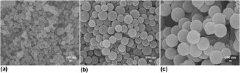
PCNSs were prepared by a hydrothermal method using glucose as a carbon source at 180 °C for 12 h at different concentrations, as shown in Fig. 1. As can be seen from the FESEM images of PCNSs, the particle sizes of PCNSs increase with increasing glucose concentration. When the concentration of a glucose solution is 0.1 mol/L, the size of PCNSs is about 100 nm, while it increases to 360 and 500 nm when the concentrations of the glucose solution are 0.2 and 0.3 mol/L, respectively. This may be because the lager concentration of the glucose solution could provide more carbon source for PCNS synthesis.
FESEM images of PCNSs by a hydrothermal method using glucose as a carbon source at 180 °C for 12 h at the concentration of (a) 0.1, (b) 0.2, and (c) 0.3 mol/L.

Our previous work has revealed that CCNSs can be used as the receptor materials in polymer solar cells, but it is too large to make a small thickness active layer, Reference Yang, Song, Li, Liu and Xu16,Reference Li, Yan, Yang, Liu and Xu17 so as to match the exciton diffusion length. Reference Dang, Hirsch, Wantz and Wuest2 So in this work, PCNSs with smallest particle size (100 nm) were selected as the receptor materials. To further study the structure of PCNSs, the surface morphology and functional groups of CCNSs and PCNSs were characterized by FESEM and FTIR for comparison. Figure S1 displays the FESEM images of as-synthesized CCNSs [Fig. S1(a)] and PCNSs [Fig. S1(b)]. It can be seen that CCNSs exist in an aggregated state because of intensive van der Waals attractive force and have nonpolar nature and inert surface, which results in a poor dispersibility in common solvents, inducing poor optical properties of the composite. Reference Yan, Li, Yang, Liu, Chen and Xu18 As can be seen from the insets, the surfaces of PCNSs [Fig. S1(b)] are rougher than those of CCNSs [Fig. S1(a)] and PCNSs have porous structures, Reference Zhao, Yang, Liu and Xu20 which make it possible for P3HT and PCNSs to form an interpenetrating network, resulting in good photovoltaic performance. The pore size distribution of PCNSs was determined by the Barrett–Joyner–Halen method using the desorption isotherm, as shown in Fig. S1(c). The pore diameters of the PCNSs are narrowly distributed with an average value of 0.614 nm.
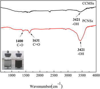
FTIR measurements were carried out to probe the surface functional groups of as-prepared CCNSs and PCNSs. As shown in Fig. 2, the CCNSs only show a weak absorption at 3421 cm−1, which is attributed to the presence of –OH. The CCNSs possess a paucity of functional group, resulting in the poor solubility in common solvents. While the PCNSs show the stronger bands of –OH (O–H stretching vibrations) at 3421 cm−1 and C=O (carboxylic acid and carbonyl moieties) at 1631 cm−1, along with the weak peak at 1400 cm−1 arising from the C–O stretching vibrations. The results show that the as-prepared PCNSs are rich in hydroxyl, carbonyl, and carboxylic groups on the surfaces. The presence of O-rich groups makes PCNSs to better disperse in aqueous medium and some common organic solvents, which facilitates the applications in nonaqueous phase and organic devices. The dispersion images of CNSs in chlorobenzene (inset of Fig. 2) show that PCNSs exhibit better dispersion than CCNSs, confirming that the presence of O-rich groups makes PCNSs to better disperse in chlorobenzene, which is in accordance with the FTIR analysis.
FTIR spectra of CCNSs and PCNSs. Inset: dispersion images of CNSs in chlorobenzene, (a) CCNSs and (b) PCNSs.

Given the low crystallization of as-synthesized PCNSs prepared by a hydrothermal method, a high temperature (800 °C) annealing treatment of PCNSs was carried out for comparison. Figure S2 displays the FTIR spectra of as-prepared PCNSs and PCNSs after heat-treatment. The result shows that after heat-treatment, PCNSs show a weak band of –OH at 3421 cm−1 and the absorption bands of C=O and C–O are weakened obviously, indicating the decomposition and release of the O-rich groups on the surface of PCNSs during heat-treatment, which might be unfavorable for the dispersion of PCNSs in common organic solvents. The dispersion images of as-prepared PCNSs and PCNSs with heat-treatment in chlorobenzene (inset of Fig. S2) also show that, PCNSs, after heat treatment, show a poor dispersion, illustrating the negative effect of heat-treatment on film formation. Besides, the crystallinity of PCNSs has a great influence on the photoproperties of the composite films. High crystallinity should be conductive to improve the photoproperties of the composite films. As the formation of good film is the foundation of good photoproperties of the composite films, a compromise could be reached to maximize the crystallinity of PCNSs under the precondition of ensuring good dispersion in common organic solvents. Though as-synthesized PCNSs were chosen for follow up investigations in the present study, the ideal condition would be a combination of both good dispersibility in solvents and high crystallinity of PCNSs, as will be discussed in our ongoing researches.
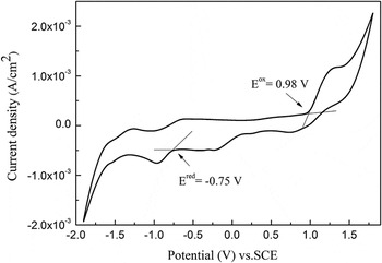
To demonstrate the potential application of the PCNSs in photovoltaic cells, we carried out CV measurement of PCNSs for determining their band gap energies, as shown in Fig. 3. The CV of PCNSs reveals well-defined oxidation and reduction peaks. As can be seen from the CV curve, the onset oxidation potential
 $\left( {E_0^{{\rm{ox}}}} \right)$
and reduction potential
 $\left( {E_0^{{\rm{red}}}} \right)$
of PCNSs are 0.98 and −0.75 V, respectively. From
 $E_0^{{\rm{ox}}}$
and
 $E_0^{{\rm{red}}}$
, the highest occupied and lowest unoccupied molecular orbitals (HOMO and LUMO, respectively) energy levels as well as the energy gaps (E
g) can be calculated, according to Eqs. (1) and (2). Therefore, HOMO is −5.72 eV and LUMO is −3.99 eV below the vacuum energy level. E
g is calculated to be 1.73 eV by E
g = E
LUMO − E
HOMO.
 $${\rm{HOMO}} = - \left( {{{\rm{e}}^{E_0^{{\rm{ox}}}}} + 4.74} \right)\;\left( {{\rm{eV}}} \right)\quad ,$$
 $${\rm{LUMO}} = - \left( {{{\rm{e}}^{E_0^{{\rm{red}}}}} + 4.74} \right)\;\left( {{\rm{eV}}} \right)\quad ,$$
 $${V_{{\rm{OC}}}} = {{\rm{e}}^{ - 1}} \times \left( {\left| {{\rm{HOM}}{{\rm{O}}^{{\rm{donor}}}}} \right| - \left| {{\rm{LUM}}{{\rm{O}}^{{\rm{acceptor}}}}} \right| - 0.3\;{\rm{eV}}} \right)\quad .$$
CV curves of PCNSs in 0.1 M TBAP, at a scan rate of 50 mV/s.

Free holes and electrons can not be created directly in composite films when light is absorbed because the excitons have a large binding energy (0.3 eV), Reference Subbiah, Amb, Irfan, Gao, Reynolds and So21 so the energy gaps of electron donors and electron acceptors △E 1 and △E 3 (△E 1 = DLUMO − ALUMO, △E 3 = DHOMO − AHOMO, D refers to electron donors, A refers to electron acceptors) should be greater than the exciton binding energy. The HOMO and LUMO of P3HT are −5.0 and −3.0 eV, Reference Subbiah, Amb, Irfan, Gao, Reynolds and So21 respectively. As a result, △E 1 and △E 3 of the active layer based on P3HT and PCNSs are 0.72 and 0.99 eV, greater than the exciton binding energy. Therefore, PCNSs would be suitable to be used as the receptor materials of polymer solar cells. For donor–acceptor bulk heterojunction solar cells, the V oc is mainly determined by the difference in the acceptor's LUMO and the donor's HOMO. Reference Li, Hu, Zhao, Shi, Deng, Hou and Qu22 In our P3HT:PCNS films, the HOMO level for P3HT is −5.0 eV, the LUMO of PCNSs is estimated to be −3.99 eV by electrochemical methods; thus, the V oc of the P3HT:PCNS-based device is determined to be around 0.7 V, according to Eq. (3).
B. Characterization of P3HT:PCNS composite films
As mentioned above, PCNSs, a fullerene-like spherical structure carbon material with rough surface and porous structure for a large interface, should have potential for the electron-acceptors in photovoltaic devices. Therefore, we explored the optical properties of as-fabricated P3HT:PCNS composite films. The performance of photovoltaic devices depends strongly on the mixture ratio of blends with donor and acceptor, revolving speed, and suspension concentration. Besides, thermal treatment has been proven to be successful in controlling the nanomorphology of active layer, so the influence of mixture ratio, spin-coating speed, suspension concentration, and annealing on the optical properties of P3HT:PCNS films was investigated in this study.
1. Influence of P3HT:PCNS ratio on the blends
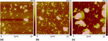
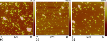
To investigate the influence of mixture ratio on the morphology of P3HT:PCNS films, four kinds of solutions (A, B, C, and D) mentioned above were spin coated on the PEDOT:PASS-coated substrates at a spin rate of 1000 rpm for 1 min and characterized by AFM. The AFM images of the composite films prepared under different ratios (P3HT:PCNSs of 4:1, 2:1, 1:1, w/w) are shown in Fig. 4. When the P3HT:PCNS ratio is 4:1 [Fig. 4(a)], the distribution of PCNSs in P3HT is sparse because of the small quantity of PCNSs, which is not favorable for the interface charge delivery between the donor and acceptor. As the PCNS amount increases, the density of films is improved. When the PCNS:P3HT ratio is 2:1 [Fig. 4(b)], PCNSs have a good dispersion in P3HT, thus an interpenetrating network structure in the film is formed. While when the PCNS:P3HT ratio is 1:1 [Fig. 4(c)], PCNSs appear a large area of aggregation, resulting in the decrease of the contact area between P3HT and PCNSs, which is not favorable for the enhancement of efficiency.
AFM images of P3HT:PCNS composite films prepared under different ratios of P3HT to PCNSs, (a) 4:1, (b) 2:1, and (c) 1:1.

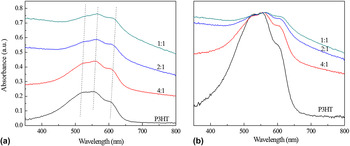
To study the optical properties of P3HT:PCNS composite films, the P3HT:PCNS mixture solutions were spin coated on quartz and characterized by UV–Vis and PL. UV–Vis spectra of P3HT:PCNS composite films with different PCNS:P3HT ratios are shown in Fig. 5. The absorption band of P3HT is in the range of 350–800 nm. Three shoulder peaks of pure P3HT film are observed at 516, 554, and 606 nm attributable to the π–π* transition, indicating good order of P3HT. Reference Thomas, Worfolk, Rider, Taschuk, Buriak and Brett23 In comparison with pure P3HT, the introduction of PCNSs causes a red-shift for the absorption spectra and the amount of red-shift increases with the proportion of PCNSs. The red-shift is in favor of increasing overlap between the absorption of P3HT:PCNS films and the solar spectra, resulting in better performance of polymer solar cells. These results indicate that there exists a strong interaction between P3HT and PCNSs, which probably increases the electron delocalization along the polymer chain, thus leading to the red-shift of the optical absorption peak. Reference Arranz-Andres and Blau24 Meanwhile, as the PCNS amount increases, the absorption intensity of P3HT:PCNS films is enhanced [as shown in Fig. 5(a)], and the absorption peak is broadened [as shown in Fig. 5(b)]. This should be caused by the absorption of PCNSs in the composite films. Besides, as can be seen from the UV–Vis spectra, when the PCNS:P3HT ratio is 2:1 and 1:1, the absorption intensity of P3HT:PCNS films is stronger.
(a) UV–Vis spectra of P3HT:PCNS composite films prepared under different ratios of P3HT to PCNSs and (b) normalized curve of the left UV–Vis spectra of P3HT:PCNSs.

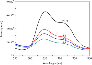
It is generally known that PL spectra in conjugated thiophenes arise from radiative recombination of polaron–exciton pairs into Franck–Condon state, and the reduction of the PL intensity gives an indication of an effective photoinduced charge transfer from the donor to acceptor. Reference Xu and Holdcroft25 Thus, the PL spectra of the P3HT:PCNS composite films with different PCNS:P3HT ratios were investigated, as shown in Fig. 6.
PL spectra of P3HT:PCNS composite films prepared under different ratios of P3HT to PCNSs (excitation at 450 nm).

From Fig. 6, it can be seen that for pure P3HT film strong PL occurs between 600 and 750 nm with excitation at 450 nm, which is significantly decreased after the PCNSs are introduced, showing that efficient charge/energy transfer occurs along the P3HT:PCNS interface. These results show that the excited fluorophore in P3HT is quenched by the electronic interactions at the P3HT:PCNS interface. By comparing to the earlier work with PCBM and carbon nanotubes, Reference Al-Ibrahim, Roth, Zhokhavets, Gobsch and Sensfuss26,Reference Berson, de Bettignies, Bailly, Guillerez and Jousselme27 the efficient quenching of PL emission shows that it is very potential for PCNSs to act as an active acceptor material for polymer cells. Besides, the reduction of PL intensity with larger PCNS contents manifests that the efficiency of charge separation is improved in P3HT:PCNS composite films. When the P3HT:PCNS ratio is 2:1 and 1:1, the fluorescence quenching is more obvious, which means more efficient charge separation of the composite films as a result of the increased interfacial areas that facilitate charge separation within the bulk. In general, from the analysis of AFM, UV–Vis, and PL results, the optimum ratio of P3HT to PCNSs in P3HT:PCNS composite films is 2:1.
2. Influence of the spin-coating speed
To study the influence of spin-coating speed on the optical properties of composite films, solution B (P3HT:PCNSs = 2:1) was selected to spin coat on the PEDOT:PSS layer at different rates (1000, 2000, and 3000 rpm) for 1 min.
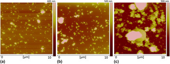
Figure 7 shows the AFM images of P3HT:PCNS composite films prepared under different spin-coating speeds. When the spinning rate is 1000 rpm [Fig. 7(a)], the obtained P3HT:PCNS composites have interstices and the PCNSs agglomerate seriously, probably because the spin-coating speed is so slow that the composites stack on the glass substrate. With the increase of spinning rate, the agglomeration of PCNSs is weakened and the as-obtained composite film becomes smooth. At the spinning rate of 2000 rpm [Fig. 7(b)], PCNSs have better dispersion and less surface defects. While, when the spinning rate increases to 3000 rpm [Fig. 7(c)], the as-obtained P3HT:PCNS composites are destroyed by the high spin-coating speed, which would do harm to film's performance. As can be seen from Fig. 7, P3HT:PCNS composite films with a spinning rate of 2000 rpm have the minimum roughness, meaning that the spinning rate of 2000 rpm is appropriate for fabricating P3HT:PCNS composite films.
AFM images of P3HT:PCNS composite films prepared under different spin-coating speeds, (a) 1000, (b) 2000, and (c) 3000 rpm.

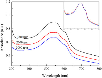
The UV–Vis spectra of P3HT:PCNS composite films prepared under different spin-coating speeds are shown in Fig. 8. The absorbance of film gradually decreases with increasing spinning rate. At a constant concentration, the film thickness should be linear with the absorbency, according to the Lambert–Beer law. Therefore, the composite film becomes thinner with the increase of spinning rate, resulting in decreased absorbance. However, from the normalized UV–Vis spectra, it can be seen that the absorption spectra of P3HT:PCNS composite films prepared under different spin-coating speeds have no significant change, indicating that different spinning rates have no obvious effect on the composition of the composite films.
UV–Vis spectra of P3HT:PCNS composite films prepared under different spin-coating speeds. Inset: normalized UV–Vis spectra of P3HT:PCNS composite films under different spin-coating speeds.

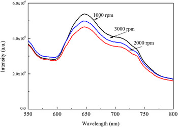
The PL spectra of P3HT:PCNS composite films prepared under different spin-coating speeds are shown in Fig. 9. The intensity of PL spectra is reduced with increasing spin-coating speed, meaning more efficient charge separation of the composite films when the spin-coating speed increases. This should be the result of the improvement in composite film quality, the weakened agglomeration of PCNSs increases the interfacial areas that facilitate charge separation within the composite films. It should be emphasized that P3HT:PCNS composite films with a spinning rate of 2000 rpm have the lowest PL intensity, meaning that the spinning rate of 2000 rpm is the optimal choice for fabricating P3HT:PCNS composite films, which is in agreement with the results of AFM observation.
PL spectra of P3HT:PCNS composite films prepared under different spin-coating speeds.

3. Influence of the suspension concentration
To investigate the influence of suspension concentration on the optical properties of P3HT:PCNS films, three kinds of solutions(E, F, and G) mentioned above were spin coated on the PEDOT:PASS-coated substrates at a spin rate of 2000 rpm for 1 min and characterized by AFM. The morphology of P3HT:PCNS composite films prepared under different suspension concentrations is illustrated in Fig. 10. As can be seen from the AFM images, when the concentration is 10 mg/mL [Fig. 10(a)], films are coarse and defective. With the increase of concentration, the defects of films are reduced. At the suspension concentration of 20 mg/mL [Fig. 10(b)], PCNSs have good dispersion and less surface defects. While when the concentration increases to 30 mg/mL [Fig. 10(c)], PCNSs aggregate seriously because of their high concentration, which is unfavorable for the charge transfer between the electron-donor and electron-acceptor materials.
AFM images of P3HT:PCNS composite films prepared under different suspension concentrations of P3HT (a) 10, (b) 20, and (c) 30 mg/mL.

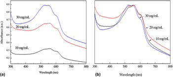
UV–Vis spectra of P3HT:PCNS composite films under different suspension concentrations were measured, as shown in Fig. 11. The absorbance of the films gradually increases along with the increase of the concentration [Fig. 11(a)]. This is because the thickness of films increases as the concentration increases. It can be seen from the normalized UV–Vis spectra [Fig. 11(b)] of P3HT:PCNS composite films that when the suspension concentration increases, the UV–Vis absorption peaks have slight blue-shift. This could be because the large concentration causes a decrease in interaction between P3HT and PCNSs, resulting in decreased electron delocalization along the polymer chain, thus leading to the blue-shift of the optical absorption peak.
(a) UV–Vis spectra of P3HT:PCNS composite films prepared under different suspension concentrations of P3HT and (b) normalized UV–Vis spectra of P3HT:PCNS composite films prepared under different suspension concentrations.

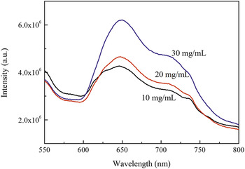
Figure 12 shows PL spectra of P3HT:PCNS composite films prepared under different suspension concentrations. The intensity of PL spectra increases with the increase of concentration. PL quenching of the composite films provides an evidence of charge transfer between P3HT and PCNSs, so the stronger intensity of PL spectra means worse charge transfer between P3HT and PCNSs. It might be the larger concentration that reduces the effective contact area of P3HT and PCNSs. As can be seen from Fig. 12, when the suspension concentration is 10 and 20 mg/mL, the intensity of PL spectra is relatively low, indicating that 10 and 20 mg/mL of concentrations are appropriate. Given the results of AFM images, 20 mg/mL is the optimum concentration for fabricating P3HT:PCNS composite films.
PL spectra of P3HT:PCNS composite films prepared under different suspension concentrations of P3HT.

From the above results, the ratio of P3HT to PCNSs of 2:1, suspension concentration of 20 mg/mL (P3HT), and spinning rate of 2000 rpm are appropriate for fabricating P3HT:PCNS composite films in favor of high performance of polymer solar cells based on PCNSs.
4. Thermal annealing of the composite films
Thermal treatment has proven to be an effective way for improving both external quantum efficiency and PCE of organic solar cells made from the blends of P3HT and PCBM. Herein, the influence of annealing on P3HT:PCNS composite films is also investigated by UV–Vis, PL, and XRD.
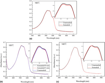
The effects of annealing on UV–Vis spectra from the P3HT:PCNS films spin coated on quartz substrates are shown in Fig. 13. These films were annealed under nitrogen atmosphere inside a glove box to avoid the influence of water and oxygen in the air. To maintain the scientific correctness of the study, we compared the films at the same location before and after annealing at different temperatures for 10 min. The absorption spectra of the films show a considerable change after annealing.
UV–Vis spectra of P3HT:PCNS composite films before and after annealing at 100 °C for 10 min, 120 °C for 10 and 15 min, and 140 °C for 10 min.

At an annealing temperature of 100 °C (Fig. 13), the absorbance intensity of the films decreases without change in the position of the absorption peaks. The decrease in the absorption strength after heat treatment may arise not only from the annealing, because the annealing time is too short to affect the composite films, but also from the oxidation of P3HT due to exposure to air during the test. The P3HT oxidation involves the radical oxidation of n-hexyl side chains and the subsequent degradation of the thiophene rings, which results in a loss of π-conjugation and bleaching of P3HT film with the low UV–Vis absorbance. Reference Endale, Sovernigo, Radivo, Zilio, Pozzato, Yohannes, Vaccari and Tormen28 However, the film heat-treated at 120 °C (Fig. 13) shows an increase in the absorption strength after heat-treatment. Since the thickness of the film is not changed, the increase in the peak absorption intensity during annealing may be attributed to the increased crystallinity of P3HT, which reduces the band gap between π and π* and improves the optical π–π* transition, resulting in increased interchain interaction among the P3HT chains. Reference Li, Shrotriya, Yao and Yang29 It can be concluded that the thermal annealing provides P3HT with energy to move and rearrange into a more ordered structure, inducing more extensive crystallization within the polymer phase. To investigate the influence of annealing time on composite films, a more five minute annealing at 120 °C was taken on the composite films. The absorption intensity further decreases. The decreased intensity of absorption may be because the prolonged annealing treatment induces aggregation of PCNSs in the films and destroys the order of P3HT. Further increasing the annealing temperature to 140 °C (Fig. 13), however, results in a decrease in the absorption intensity. From the above results, the optimum annealing temperature is 120 °C and the annealing time is 10 min.
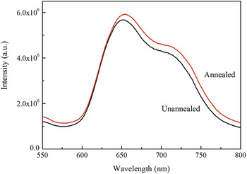
PL spectra in Fig. 14 are used to estimate the exciton quenching of P3HT:PCNS composite films before and after annealing at 120 °C for 10 min. The PL is due to the fact that the photogenerated excitons in P3HT do not take part in charge separation, while PL quenching is attributed to the interfacial charge transfer resulted from increase in interfacial area between donor and acceptor materials in active layer. Efficient PL quenching is necessary to obtain efficient organic devices, but a lager quench effect is no absolute ensure of high PCE, Reference Dang, Hirsch, Wantz and Wuest2 as the result shown by unannealed films. Compared to the untreated film, the annealed film shows enhanced fluorescence peak intensity, which may be due to the decrease in the interfacial area between P3HT and PCNSs and consequently the decrease in exciton dissociation. This illustrates that annealing activates the P3HT to move and rearrange, inducing an enhancement of phase segregation between P3HT and PCNSs. Consistent with the result of UV–Vis measurement, annealing increases the crystallization of P3HT and improves the charge carrier transport between P3HT and PCNSs. Although phase separation caused by annealing reduces exciton dissociation, the increase of optical absorption and the improved charge carrier transport after thermal annealing offset the former effect and result in an overall improvement in device performance. Reference Wang, Yang, Shieh, Yeh, Chen and Ho30
PL spectra of P3HT:PCNS composite films before and after annealing at 120 °C for 10 min.

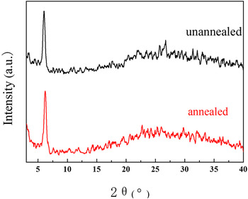
Figure 15 presents the XRD profiles of P3HT:PCNS films before and after annealing. Both films show an intense (100) diffraction peak at 6.2°, corresponding to crystallized P3HT with α-axis orientation, in which the main polymer chains are parallel and the side chains are perpendicular to substrate. Reference Liu, Liu, Li, Dong, Yao, KiddIV, Zhang, Li and Tian31 Compared with the unannealed films, the annealed P3HT:PCNS films have narrower full width at half-maximum for (100) diffraction peak, suggesting that annealing increases the crystallinity of P3HT and induces more ordered structure of P3HT. This is in good agreement with the results of UV–Vis and PL characteristics. Otherwise, both films show a weak and broad peak in the range of 20–30°, which is attributed to (002) reflection of carbon layer in PCNSs, indicating the existence of PCNSs.
XRD patterns of the P3HT:PCNS thin films before and after annealing at 120 °C for 10 min.

In summary, annealing increases the crystallinity of P3HT, leading to the increase of light absorption and enhancement of charge transport. The optimum annealing temperature and annealing time are 120 °C and 10 min, respectively.
5. Chemical structure of the composite films
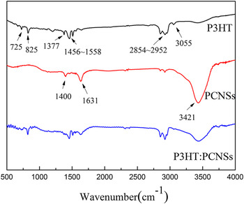
To further study the chemical structure of the P3HT:PCNS composite films, FTIR measurement of P3HT, PCNSs, and P3HT:PCNSs was conducted, as shown in Fig. 16. For P3HT, the absorption bands at 3055 and 2854–2952 cm−1 are attributed to C–H stretching vibrations in the thiophene ring, the bands at 1456–1558 cm−1 are assigned to the C=C stretching vibrations, 1377 cm−1 to CH2 stretching vibrations, 825 cm−1 to C–H bending vibrations, and 725 cm−1 to S in thiophene ring. The PCNSs show the bands of –OH stretching vibrations at 3421 cm−1 and C=O stretching vibrations at 1631 cm−1, along with the weak band at 1400 cm−1 arising from the C–O stretching vibrations. The absorption bands of P3HT:PCNSs involve all the absorption of P3HT and PCNSs, indicating the existence of P3HT and PCNSs, and the absorption band of P3HT:PCNS blends at 1631 cm−1 is weakened obviously, probably as a result of the formation of C=O…H+…S2− hydrogen bond. The hydrogen bond would make electron cloud of C=O and lone pair electrons of S transfer, leading to decreased electron cloud density. Reference Yue, Wu, Xiao, Ye, Xie, Lan, Li, Huang and Lin32 Although the absorption band and strength change a little, P3HT:PCNS blend still retains P3HT and PCNS bands, illustrating no formation of new compounds.
FTIR spectra of P3HT, PCNSs, and P3HT:PCNSs.

VII. CONCLUSION
PCNSs, with a diameter of 100 nm and porous structure, would be suitable to be used as the receptor materials of polymer solar cells because of their matchable energy level with P3HT and good solubility in organic solvent. The optical properties of the P3HT:PCNSs depend strongly on the mixture ratio of P3HT and PCNSs, revolving speed, and suspension concentration during spin coating. The optimum ratio (2:1) of the P3HT:PCNSs in our experiment will ensure a balance between efficient dissociation of excitons and effective charge transport. Appropriate revolving speed (2000 rpm) improves the quality of P3HT:PCNS films, making for increased interfacial areas that facilitate charge separation within the composite films. Proper concentration (20 mg/mL) provides more effective contact area of P3HT and PCNSs, causing a better charge transfer. Annealing increases the crystallinity of P3HT, which results in enhanced visible light absorption and increased charge transport in composite film. The optimum annealing temperature and annealing time for P3HT:PCNS composite films are 120 °C and 10 min, respectively. This study chooses PCNSs as receptor materials of polymer solar cells; it is lower cost, simpler technology, higher specific surface area, and better dispersibility in solvents, as compared with CCNSs. The disadvantage is that the crystallinity of PCNSs prepared by a hydrothermal method is relatively low to make sure high photoproperties of the composite films. The ideal condition would be a combination of both good dispersibility in solvents and high crystallinity of PCNSs, as in our ongoing researches. Otherwise, the influence of mixture ratio, spin-coating speed, suspension concentration, and annealing on the optical property of P3HT:PCNS films was investigated in this study. This lays an experimental and theoretical foundation for fabricating polymer solar cells with PCNSs. The further study is ongoing in optimization for photovoltaic properties of the solar cells based on P3HT:PCNSs.
Supplementary Material
To view supplementary material for this article, please visit http://dx.doi.org/jmr.2014.108.
ACKNOWLEDGMENTS
The authors would like to thank Suzhou Institute of Nano-Tech and Nano-Bionics, Chinese Academy of Sciences for atomic force microscope test. This work was supported by National Natural Science Foundation of China (21176169), Shanxi Provincial Key Innovative Research Team in Science and Technology (2012041011), International Science & Technology Cooperation Program of China (2012DFR50460), Research Project Supported by Shanxi Scholarship Council of China (2012-038), Postgraduate Innovation Program of Shanxi Province (20143010), and Postgraduate Innovation Foundation of Taiyuan University of Technology (S2014103).