1. Introduction
1.1. Purpose of this work
Multibody dynamics is a powerful tool for the systematic simulation, analysis, and optimization of the motion of mechanical systems and has a vast spectrum of application in several engineering areas. A multibody system is composed of three main ingredients, namely, a collection of interconnected rigid and/or flexible bodies describing large rotational and translational motions, joints that kinematically constrain the relative motion of the adjacent bodies, and force or driving elements acting upon those bodies. The Newton–Euler formulation is among the most widely utilized methodologies to model multibody robotic systems due to its simplicity and straightforward to apply in general-purpose codes, being the main approach adopted in this work. Integrating multibody dynamics formulations into the modeling and simulation of robotic systems can significantly improve the understanding of their behavior and performance, particularly in scenarios involving contacts and interactions of complex nature. This knowledge can be essential for the design, control, and optimization of robots that operate in real-world environments. Thus, the main purpose of this paper is to provide a comprehensive analysis of multibody dynamics in robotics, with particular focus on applications that involve contact-impact events. The presented approaches allow for an accurate representation of the dynamic response, contact forces, and frictional effects, providing valuable insights for the design, analysis, and optimization of robotic systems. In the sequel of this process, the key ingredients associated with kinematic and dynamic aspects in multibody systems are revisited. Then, an overview of the main normal and tangential force models is offered. Finally, two robotics systems that involve contact-impact scenarios are used to demonstrated the presented methodologies.
1.2. Multibody dynamics in robotics
In the specific domain of robotics, multibody dynamics has emerged as a vital and widely employed approach for investigating and understanding the movement and dynamic responses of robots in diverse real-world scenarios [Reference Antonya and Boboc1, Reference Li, Li, Li, Zhu and Samani2]. In fact, multibody dynamics provides an accurate representation of robotic behavior, in the measure that robotic systems typically consist of multiple interconnected bodies, linked by joints, and subjected to external forces. This is especially relevant considering the significant body displacement associated with the locomotion of robots [Reference Zhang, Zhang and Elsabbagh3, Reference You, Liu and Ma4].
Over the past few decades, the analysis of robotic systems using multibody dynamics methodologies has been a subject of extensive investigation. Grazioso et al. [Reference Grazioso, Ugenti, Galati, Mantriota and Reina5] presented and validated a new passive articulated suspension tracked robot using multibody dynamics methodologies. For this purpose, the commercial software MSC Adams was utilized to develop the multibody model, which was considered in the design and optimization of the solution obtained. The performance of the multibody model was compared and validated with experimental data, being, subsequently, utilized to examine its effectiveness in different challenging environments. Mucchi and co-workers [Reference Mucchi, Fiorati, Di Gregorio and Dalpiaz6] validated a flexible multibody model of a commercial 3R planar manipulator. This manipulator consists of five rigid bodies and 11 massless parts interconnected by nine revolute joints. Flexibility was incorporated in the base and in the joints. In this study, the flexible multibody model was utilized to study low-frequency vibrations that can be generated during particular installation conditions of industrial serial planar manipulators. Bascetta et al. [Reference Bascetta, Ferretti and Scaglioni7] developed a closed-form multibody dynamic model of flexible manipulators using the Newton–Euler formulation. In this investigation, the utilization of the Newton–Euler approach, articulated in terms of joint and elastic variables, not only enhances simulation performance but also makes the model well-suited for real-time control and active vibration damping. The multibody model was compared and validated with benchmarks from the literature obtained through the classical multibody approach. Additionally, further validation was conducted by comparing the model with experiments conducted on an experimental manipulator.
Chang and co-authors [Reference Chang, An and Ma8] modeled and developed a quadruped legged with the aim at identifying the dynamic parameters related to systems behavior. In this investigation, the Gazebo software was utilized to assess the performance of a quadruped robot with a total of 16 degrees-of-freedom. Vasileiou et al. [Reference Vasileiou, Smyrli, Drogosis and Papadopoulos9] presented a unified framework to develop a passive robot using multibody dynamics for that purpose, being the computational results compared and validated with data collected from an experimental prototype. These authors demonstrated the effectiveness of using digital twin in the design and development process of walking robots [Reference Grazioso, Ugenti, Galati, Mantriota and Reina5, Reference Safartoobi, Dardel and Daniali10]. In turn, Kim et al. [Reference Kim, Moon, Bae and Park11] proposed a method to simulate multibody robotic systems driven by DC motors, based on the Newton–Euler method, to account for the electromechanical coupling effects, which allows a more realistic and reliable prediction of the dynamic responses of such systems. The proposed model was utilized in the analysis of two robotic systems equipped with DC motors, namely an industrial robot and a flexible satellite antenna. Ingrosso et al. [Reference Ingrosso, De Palma, Avanzini and Indiveri12] developed a rigid multibody model of an underwater multi-hull vehicle to compute the lumped parameter hydrodynamic derivative matrices using the multibody approach.
Robotic technologies are also utilized in specific tasks that are difficult, repetitive, or unsafe for humans [Reference Coelho, Ribeiro, Dias, Lopes and Flores13–Reference Wadi and Mukhopadhyay15]. In this context, Kim et al. [Reference Kim, Yang and Abdel-Malek16] adopted the Lagrange formulation and introduced a method for planning load-effective dynamic motions for redundant systems. The authors demonstrated the applicability of the proposed method in pulling tasks using a highly articulated 30 degrees-of-freedom human model of the torso and arms. Zhang and Zhang [Reference Zhang and Zhang17] designed and developed a lower limb exoskeleton robots’ dynamics parameters identification based on improved beetle swarm optimization algorithm, in which a beetle swarm optimization methodology was designed and utilized to identify the dynamics parameters of the robot system. The proposed approach was developed with basis on the beetle antennae search algorithm and particle swarm optimization. Experimental investigation carried out on an exoskeleton model was used to demonstrate the accuracy and effectiveness of the proposed solution. More recently, Gonçalves et al. [Reference Gonçalves, Ribeiro, Ribeiro, Lopes and Flores18, Reference Gonçalves, Ribeiro, Ribeiro, Lopes and Flores19] developed a human-like mobile domestic robot, called CHARMIE, to improve the healthcare and quality of life of elderly people by performing household chores. The multibody model of the CHARMIE robot has been developed utilizing the well-established Newton–Euler formulation and it is composed of 40 rigid bodies, interconnected by 34 revolute joints, ten prismatic joints, and three rigid joints.
Nature-inspired robots, which can be helpful in hazardous or confined environments, such as ruins and rubbles of collapsed buildings, nuclear power plants, pipelines, or surgical procedures, have also been developed within the framework of multibody dynamics [Reference Transeth, Pettersen and Liljebäck20]. Vossoughi et al. [Reference Vossoughi, Pendar, Heidari and Mohammadi21] proposed a new planar structure for a n-link snake-like robot to obtain passive motion by using springs in series with angular displacement actuators. The Gibbs–Appell formulation [Reference Mirtaheri and Zohoor22] was used to develop the dynamic equations of motion in a horizontal plane. This approach is quite interesting, not only because it allows permits the simplification in the dynamic equations but also it results in a very efficient solution in terms of the computational effort. The obtained results demonstrate that with the appropriate selection of initial conditions, joint angles operate in a limit cycle, allowing the robot to move steadily along a passive trajectory. Talaeizadeh et al. [Reference Talaeizadeh, Forootan, Zabihi and Pishkenari23] also considered a snake-like robot model to compare the performance of a variant of the Kane’s formulation with six different techniques based on the Lagrange’s formulation. In order to assess the effectiveness of the mentioned methods, a snake-like robot was utilized, and several aspects, such as the number of the most time-consuming computational operations, constraint error, energy error, and CPU time allocated to each method were investigated. Saunders et al. [Reference Saunders, Golden, White and Rife24] investigated the possibility of obtaining accurate optimal gait patterns for soft-body robots using a lumped dynamic model. These authors used a caterpillar-like soft robot to validate the approach. The problem of modeling and studying soft robots based on caterpillar locomotion was also object of investigation by Zou et al. [Reference Zou, Lin, Ji and Yang25], who developed a new robot capable of moving at 18.5 m/h. The modular structure of this robot is crucial to ensure a good ability to cope with the challenges of different environments and tasks. More recently, Jia and co-authors [Reference Jia, Cheng, Ye, Xie and Wu26] proposed a new amphibious soft-rigid wheeled crawling robot that is composed by a soft-rigid body actuated by two soft pneumatic actuators, four wheels, and four annular soft bladders as brakes. The solution developed and built was very good in terms of locomotion performance in amphibious environment.
The modeling of the contact-impact phenomenon is one of the most important issues in the analysis of robotic systems. Many authors have recognized the critical role that the selection of the contact force model plays in the modeling and analysis of dynamical systems, and numerous normal and tangential contact force models have been extensively documented in the literature [Reference Banerjee, Chanda and Das27–Reference Vukobratović and Potkonjak33]. Contact conditions introduce complexities in the system that are effectively addressed through multibody dynamics simulations. These simulations allow researchers and engineers to study how robots respond to different terrains, forces, and environmental conditions. Two main steps must be considered in a contact problem in multibody dynamics, namely (i) the definition of the geometric properties of the surfaces in contact, together with the development of a methodology to access whether contact is occurring, and (ii) the calculation of the contact forces resulting from the collision. The modeling of contact-impact events strongly depends on multiple factors, such as the geometry of the contacting surfaces, the local physical properties, and the numerical representation of the interaction between the contacting bodies [Reference Saraiva, Rodrigues da Silva, Marques, Tavares da Silva and Flores34, Reference Vukobratovic, Potkonjak and Matijevic35]. In robotics, three main types of contact-impact phenomena can be considered, namely, the contacts than can take place between the robot’s feet and the ground, the contacts arising from joint’s clearance, and the interaction between the robot and the surrounding environment. This last issue is particularly relevant for applications in which robots are required to navigate through dynamic, unstructured, and uneven environments [Reference Loganathan and Ahmad36–Reference Mehdian and Rahnejat39].
Multibody dynamics methodologies have also been applied in the process of modeling and studying several robotic systems to deal with the contact-impact phenomenon. Varedi-Koulaei et al. [Reference Varedi-Koulaei, Daniali and Farajtabar40] studied the dynamic behavior of a 3RRR planar parallel manipulator consisting of an equilateral triangular platform connected to the base by three legs, each of them composed of two bodies and three revolute clearance joints. Regularized models, for both normal and tangential forces, were considered to compute the intra-joint contact-impact forces developed at the clearance joints. In particular, the classical Hertz contact approach, incorporated with a dissipative term, was utilized to determine the normal contact forces. In turn, a Coulomb’s friction force model was used to evaluate the tangential forces due the friction effect. Guo and co-authors [Reference Guo, Cheng, Wang and Li41] analyzed the dynamic response of a rigid-flexible multibody approach together with joint clearance in a 5-DOF polishing robot. In this work, the authors provided the theoretical background to improve the motion accuracy and dynamic performance of this type of hybrid polishing robot. In turn, Tian et al. [Reference Tian, Lv, Sun, Zhao, Jiang, Han, Gu and Cheng42] developed an adaptive impedance control method for the pneumatic servo-polishing system of the robot to ensure a constant contact force control problem between the end tool of a 5 degrees of freedom hybrid optical mirror processing robot and a workpiece. The computational and experimental results demonstrated the effectiveness of the presented approach, both in terms of accuracy and adaptability. Zahedi et al. [Reference Zahedi, Shafei and Shamsi43] proposed a direct and simple formulation to derive the multibody equations of motion for constrained robotic mechanisms with multiple closed loops, which was verified with an experimental study. Farhat et al. [Reference Farhat, Mata, Page and Díaz-Rodríguez44] presented a switch algorithm to solve the discontinuity problem associated with the Coulomb’s friction force model, which results in stiff differential equations in the simulation process. The proposed algorithm was utilized to study a simple one degree-of-freedom oscillator, and a three degrees-of-freedom RPS parallel manipulator. Ahmadizadeh et al. [Reference Ahmadizadeh, Shafei and Fooladi45] modeled the contact-impact phenomenon in a multibody system composed of four rigid links connected by revolute joints. Different normal contact force models have been evaluated in the dynamic response of the multibody system. These authors demonstrated that the system response includes both non-impact and impact scenarios, which eventually affect the computational resolution of the equations of motion due to the very short collisions.
The contact interaction between robot’s feet and ground is a ubiquitous scenario in humanoid robots and legged locomotion systems. Understanding how feet make contact with and respond to diverse surfaces is essential for activities like walking, running, or maintaining stability [Reference Schiehlen46, Reference Taheri and Mozayani47]. Mahapatra et al. [Reference Mahapatra, Roy and Pratihar48] studied the contact events between the ground and the feet of a hexapod robot in different types of terrain to improve the gait energy consumption. In this work, the authors used regularized forces models to evaluate the normal and friction forces developed during the collision events. He and Ren [Reference He and Ren49] proposed a numerical framework of the limit cycle walking based on multibody dynamics methodologies, focusing specifically on the interaction between the feet and the ground. These authors used a planar model composed of five rigid bodies, namely, two legs, two feet and the torso, connected by revolute joints. Geometrically, the ground was considered to be a planar surface, and the feet were considered as spheres or a series of points. Liu et al. [Reference Liu, Gao, Rao, Ding and Liu50] modeled and studied the dynamics of passive biped robot in terms of gait bifurcation, intermittency and crisis, which allows for designing controllers with less stringent torque requirements on biped walking robots. Tang and co-authors [Reference Tang, Zhang and Zhang51] proposed a new method to deal with earth-contact mechanism’s performance map based on the digital terrain map, which helps the control system and operator to make the optimal control decision. The main benefits of the presented approach were examined with experiments.
The concept of contact joint was introduced by Hu and Guo [Reference Hu and Guo52] to model the foot–environment contact in challenging environments where the terrain may be composed of uneven and slippery surfaces. The authors validated their approach using a hexapod robot, with each leg consisting of a 2-UPS/UP parallel mechanism and a flat foot connected by a spherical joint. The proposed concept of a contact joint characterized the permissible foot motion, taking into account the geometric interactions between the foot and the environment. Tang et al. [Reference Tang, Li, Zhang, Zhang and Yu53] presented a new knee exoskeleton with remote-center-of-motion mechanism with the purpose to improve the kinematic synergy between the exoskeleton and the human body. The authors proved the accuracy and applicability of their solution with data obtained from an experimental apparatus, being suggested the new design guidelines can be considered to better investigate exoskeleton robots for biomechanics human gait performance. David and Bruneau [Reference David and Bruneau54] presented a method, named sequential method of analytical potential, to generate dynamic walking gaits for bipedal robots. In this investigation, the authors used the Lagrange’s formulation to develop a multibody model of the bipedal robot Rabbit and considered a single-point contact at the leg. The proposed approach had the advantage to be a unified framework, encompassing both the dynamics in the operational space and the system’s instantaneous capabilities and limits, enabling a comprehensive understanding of the system’s dynamic performance in the operational space [Reference Kherici and Mohamed Ben Ali55].
2. Multibody formulations for robotics
2.1. Kinematic aspects of constraints in multibody systems
With the aim of formulating the equations of motion that govern the dynamic response of robotic systems, it is first necessary to elaborate on the key aspects related to their kinematic structures. By and large, the two main spatial joints utilized to model robotic systems are the spherical and revolute joints, which are briefly described in the following paragraphs. For a more in-depth exploration of multibody systems formulations, interested readers are directed to the work authored by Nikravesh [Reference Nikravesh56].
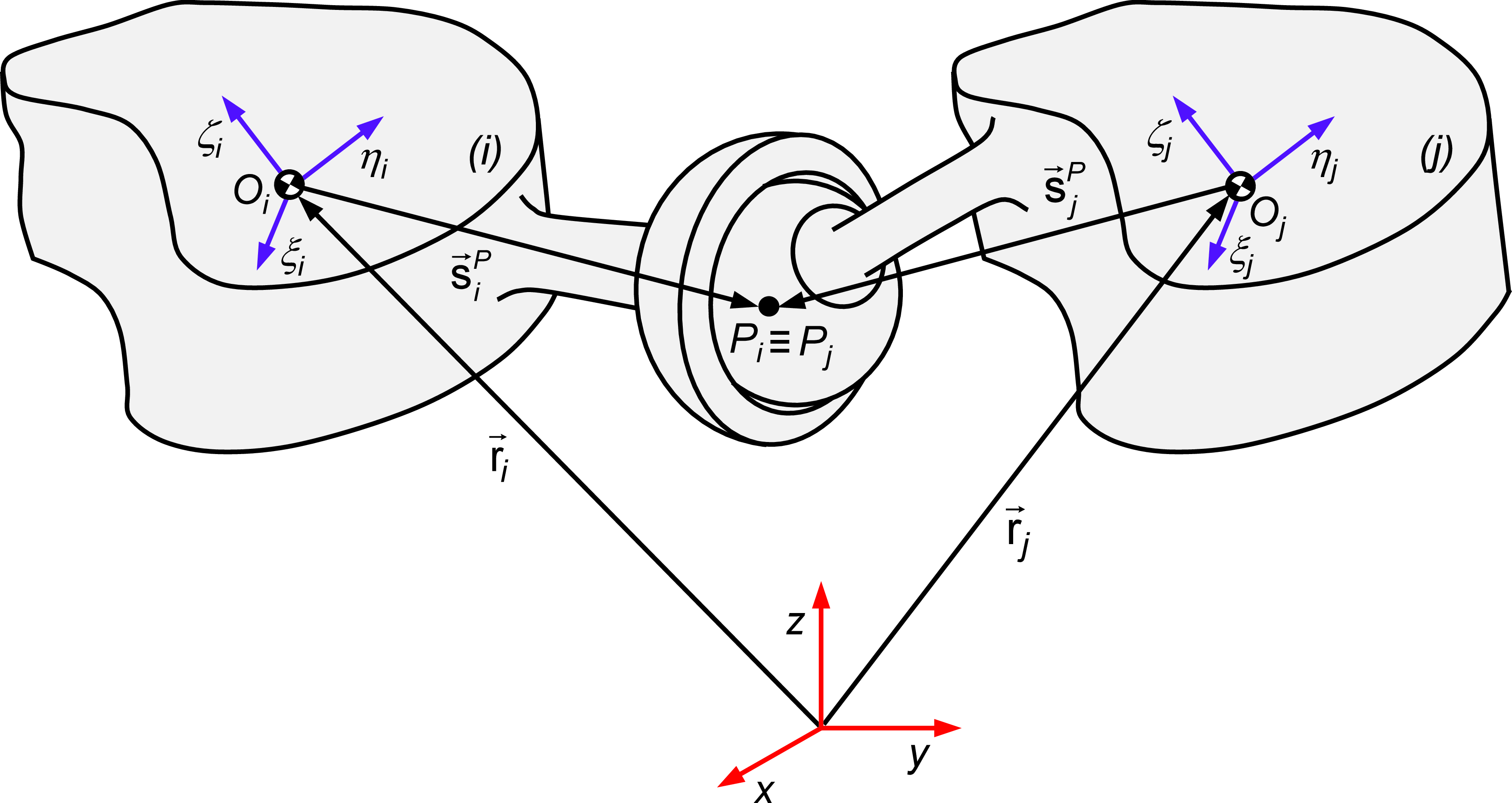
Representation of a spherical joint linking two generic bodies i and j.

Fig. 1 illustrates a typical spherical joint, commonly referred to as a ball-and-socket joint. This particular kinematic pair restricts the relative translations between the two adjacent bodies, denoted as i and j, while allowing for three relative rotations. Thus, the center of the spherical joint has constant coordinates with respect to any of the local coordinate systems of the connected bodies. In other words, a spherical joint establishes that the point P i on body i shares the same position as the point P j on body j. The kinematic constraints associated with a spherical joint can be written as [Reference Nikravesh56–Reference Rodrigues da Silva, Marques, Tavares da Silva and Flores58]
 \begin{equation} \boldsymbol{\Phi }^{\left(s,3\right)}\equiv \textbf{r}_{j}^{P}-\textbf{r}_{i}^{P}=\textbf{r}_{j}+\textbf{s}_{j}^{P}-\textbf{r}_{i}-\textbf{s}_{i}^{P}=\textbf{0} \end{equation}
in which, r and s denote the position vectors with respect to the global coordinate system xyz. The three scalar constraint equations implied by Eq. (1) restrict the relative position of points P i and P j . Thus, there are three degrees of freedom between two bodies connected by a spherical joint. The contributions to the Jacobian matrix (J) of the constraints and to the right-hand side (γ) of the acceleration constraint equations can be derived conventionally, leading to the following expressions [Reference Nikravesh56],
 \begin{equation} \textbf{D}_{\left(3\times 12\right)}^{\left(s,3\right)}=\left[\begin{array}{l@{\quad}l@{\quad}l@{\quad}l} -\textbf{I} & \tilde{\textbf{s}}_{i}^{P} & \textbf{I} & -\tilde{\textbf{s}}_{j}^{P} \end{array}\right] \end{equation}
 \begin{equation} \unicode{x1D6C4}^{\left(s,3\right)}=-\tilde{\dot{\textbf{s}}}_{i}^{P}\unicode{x1D6DA}_{i}+\tilde{\dot{\textbf{s}}}_{j}^{P}\unicode{x1D6DA}_{j} \end{equation}
where I is the 3 × 3 identity matrix, (∼) represents the skew-symmetric vector, (·) is the first derivative with respect to time, and
 $\unicode{x1D6DA}$
denotes the angular velocity vector [Reference Rodrigues da Silva, Marques, Tavares da Silva and Flores58].
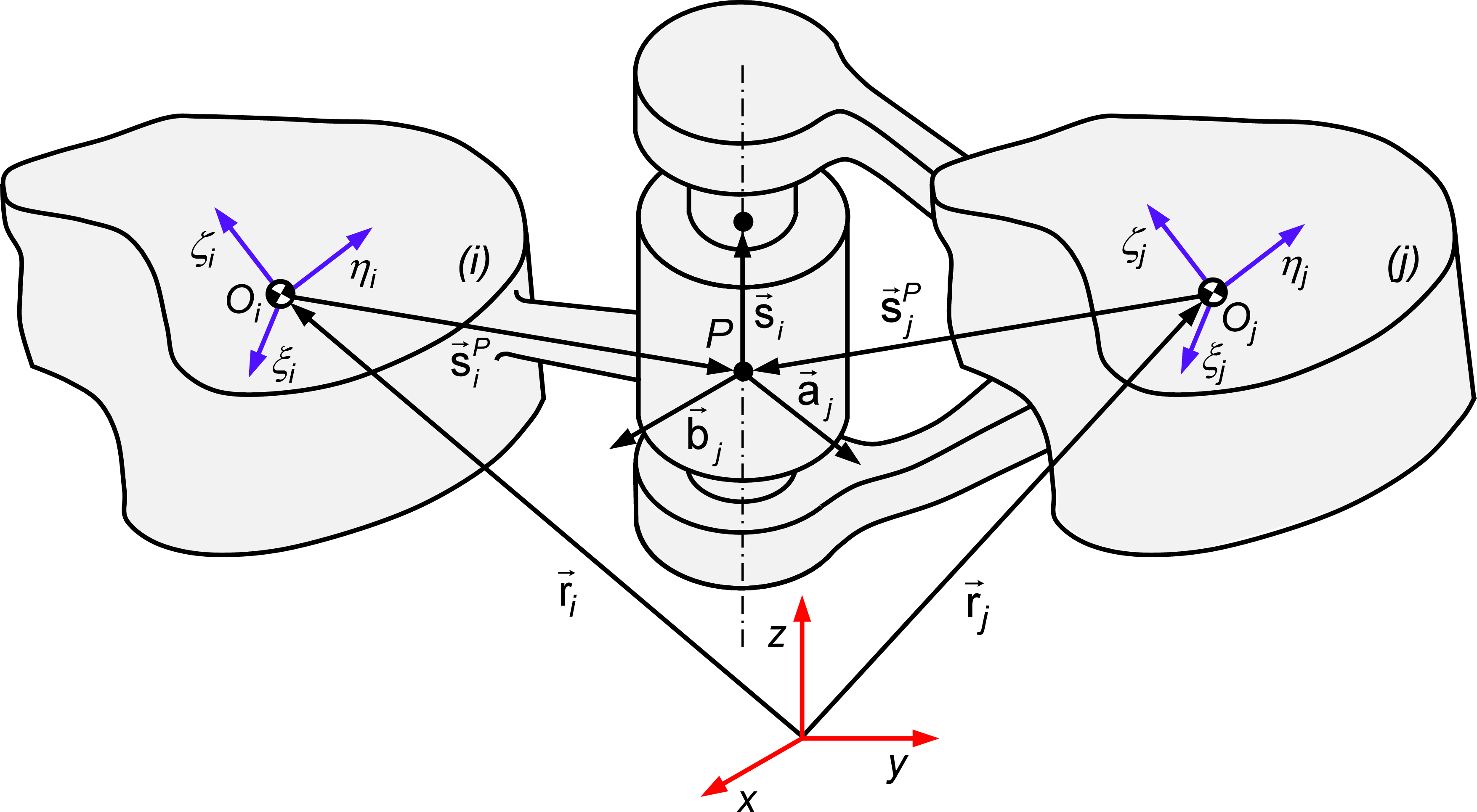
Representation of a revolute joint linking two generic bodies i and j.

A typical revolute joint, linking two generic bodies i and j, consists of a journal and a bearing. It allows a relative rotation about a common axis while preventing relative translation along this axis. Thus, Eq. (1) is imposed on an arbitrary point p located on the joint axis. Let us consider two vectors a j and b j on body j perpendicular to each other and perpendicular to the joint axis, as illustrated in the representation of Fig. 2. It is clear that these two vectors must remain perpendicular to vector s i defined along the joint axis. Therefore, five constraint equations for a revolute joint can be expressed as [Reference Nikravesh56]
 \begin{equation} \boldsymbol{\Phi }^{\left(r,5\right)}\equiv \left\{\begin{array}{c} \boldsymbol{\Phi }^{\left(s,3\right)}\equiv \textbf{r}_{j}+\textbf{s}_{j}^{P}-\textbf{r}_{i}-\textbf{s}_{i}^{P}=\textbf{0}\\[5pt] \mathit{\Phi }^{\left(n1,1\right)}\equiv \textbf{s}_{i}^{\textrm{T}}\textbf{a}_{j}=0\\[5pt] \mathit{\Phi }^{\left(n1,1\right)}\equiv \textbf{s}_{i}^{\textrm{T}}\textbf{b}_{j}=0 \end{array}\right. \end{equation}
In turn, the contributions to the Jacobian matrix, J, of the constraints and to the right-hand side, γ, of the acceleration constraint equations related to a revolute joint can be formulated as [Reference Nikravesh56]
 \begin{equation} \textbf{D}_{\left(5\times 12\right)}^{\left(r,5\right)}=\left[\begin{array}{c@{\quad}c@{\quad}c@{\quad}c} -\textbf{I} & \tilde{\textbf{s}}_{i}^{P} & \textbf{I} & -\tilde{\textbf{s}}_{j}^{P}\\[5pt] \textbf{0} & -\textbf{a}_{j}^{\textrm{T}}\tilde{\textbf{s}}_{i} & \textbf{0} & -\textbf{s}_{i}^{\textrm{T}}\tilde{\textbf{a}}_{j}\\[5pt] \textbf{0} & -\textbf{b}_{j}^{\textrm{T}}\tilde{\textbf{s}}_{i} & \textbf{0} & -\textbf{s}_{i}^{\textrm{T}}\tilde{\textbf{b}}_{j} \end{array}\right] \end{equation}
 \begin{equation} \unicode{x1D6C4}^{\left(r,5\right)}=\left\{\begin{array}{c} -\tilde{\dot{\textbf{s}}}_{i}^{P}\unicode{x1D6DA}_{i}+\tilde{\dot{\textbf{s}}}_{j}^{P}\unicode{x1D6DA}_{j}\\[5pt] -\textbf{s}_{i}^{\textrm{T}}\tilde{\unicode{x1D6DA}}_{j}\dot{\textbf{a}}_{j}-\textbf{a}_{j}^{\textrm{T}}\tilde{\unicode{x1D6DA}}_{i}\dot{\textbf{s}}_{i}-2\dot{\textbf{a}}_{j}^{\textrm{T}}\dot{\textbf{s}}_{i}\\[5pt] -\textbf{s}_{i}^{\textrm{T}}\tilde{\unicode{x1D6DA}}_{j}\dot{\textbf{b}}_{j}-\textbf{b}_{j}^{\textrm{T}}\tilde{\unicode{x1D6DA}}_{i}\dot{\textbf{s}}_{i}-2\dot{\textbf{b}}_{j}^{\textrm{T}}\dot{\textbf{s}}_{i} \end{array}\right. \end{equation}
The kinematic constraint equations for a generic multibody system can be represented as [Reference Flores59]
 \begin{equation} \boldsymbol{\Phi }\equiv \boldsymbol{\Phi }\left(\textbf{q}\right)=\textbf{0} \end{equation}
where q is the vector of body coordinates, and Φ is a function that describes the kinematic constraints.
The first time derivative of Eq. (7) yields the velocity constraints that provide relations between the velocity variables of a system. The velocity constraints can be expressed as
 \begin{equation} \dot{\boldsymbol{\Phi }}\equiv \textbf{Dv}=\textbf{0} \end{equation}
in which D denotes the Jacobian matrix and v contains the velocity terms. For driving elements, the corresponding velocity constraint equations can be written in the form [Reference Nikravesh56]
 \begin{equation} \dot{\boldsymbol{\Phi }}\equiv \textbf{Dv}=\unicode{x1D6D6} \end{equation}
where the right-hand side contains the partial derivates of Φ with respect to time,
 $\partial$
Φ/
 $\partial$
t. The constraints at the velocity level are formulated as linear algebraic equations
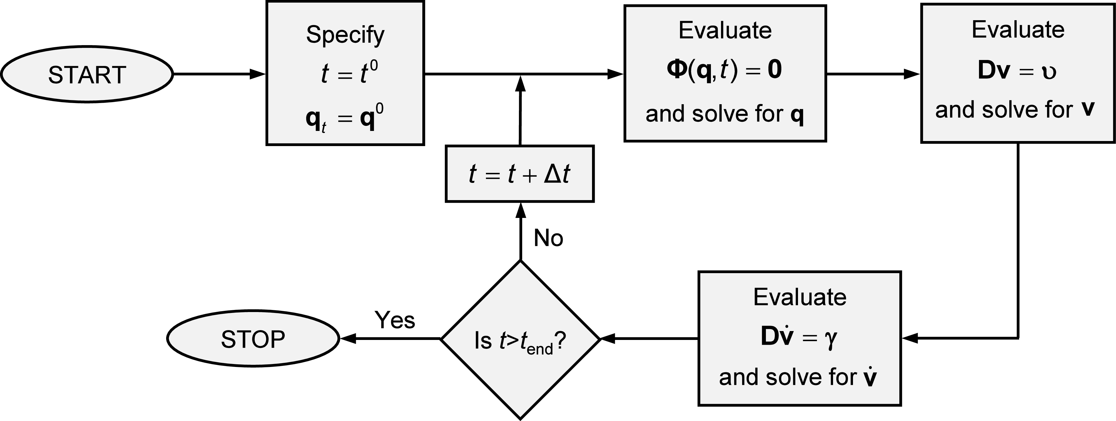
Flowchart of computational procedure for kinematic analysis of multibody systems.

The second time derivative of Eq. (7) results in
 \begin{equation} \ddot{\boldsymbol{\Phi }}\equiv \textbf{D}\dot{\textbf{v}}+\dot{\textbf{D}}\textbf{v}=\textbf{0} \end{equation}
in which
 $\dot{\textbf{v}}$
represents the acceleration terms, and the term
 $-\dot{\textbf{D}}\textbf{v}$
is the right-hand side of the kinematic acceleration equations. By defining
 $\unicode{x1D6C4}=-\dot{\textbf{D}}\textbf{v}$
, then, Eq. (9) can be rewritten
 \begin{equation} \textbf{D}\dot{\textbf{v}}=\unicode{x1D6C4} \end{equation}
In should be noticed that the terms involved in Eqs. (7) through (11) appear in a general form, that is, they do not reflect the type of coordinates considered. The constraint equations represented by Eq. (7) are nonlinear in terms of q and can be solved by employing the Newton–Raphson method. Equations (8) and (11) are linear in terms of
 $\textbf{v}$
and
 $\dot{\textbf{v}}$
, respectively, and can be solved by any standard method commonly employed for solving systems of linear equations. The kinematic analysis of a multibody systems can be carried out by solving Eqs. (7)-(11) together with the necessary driver constraints [Reference Nikravesh56]. Thus, the necessary steps to perform this type of analysis, sketched in Fig. 3, are summarized as
-
1. Specify initial conditions for positions q 0 and initialize the time t 0.
-
2. Compute the position constraint equations (7) and solve them for positions, q.
-
3. Compute the velocity constraint equations (9) and solve them for velocities, v.
-
4. Compute the acceleration constraint equations (11) and solve them for accelerations,
 $\dot{\textbf{v}}$
.
-
5. Increment the time. If the time is smaller than final time, go to step 2), otherwise stop the kinematic analysis.

2.2. Equations of motion for constrained multibody systems
The translational equations of motion for an unconstrained rigid body can be expressed as [Reference Nikravesh56]
 \begin{equation} m\ddot{\textbf{r}}=\textbf{f} \end{equation}
where m denotes the mass of the body,
 $\ddot{\textbf{r}}$
is the acceleration of the center of mass, and f represents the sum of all forces acting on the body. Nikravesh [Reference Nikravesh56] demonstrated that the rotational equations of motion for a rigid body can be expressed in the form
 \begin{equation} \textbf{J}\dot{\unicode{x1D6DA}}+\tilde{\unicode{x1D6DA}}\textbf{J}\unicode{x1D6DA}=\textbf{n} \end{equation}
in which J is the global inertia tensor,
 $\dot{\unicode{x1D6DA}}$
denotes the global angular accelerations,
 $\unicode{x1D6DA}$
is the global angular velocities, and n denotes the sum of all moments acting on the body. Thus, the translational and rotational equations of motion, commonly referred to as the Newton–Euler equations of motion, for an unconstrained body can be obtained by combining Eq. (12) and Eq. (13), which in the matrix form are written as [Reference Nikravesh56]
 \begin{equation} \left[\begin{array}{c@{\quad}c} m\textbf{I} & \textbf{0}\\[3pt] \textbf{0} & \textbf{J} \end{array}\right]\left\{\begin{array}{c} \ddot{\textbf{r}}\\[3pt] \dot{\unicode{x1D6DA}} \end{array}\right\}=\left\{\begin{array}{c} \textbf{f}\\[3pt] \textbf{n}-\tilde{\unicode{x1D6DA}}\textbf{J}\unicode{x1D6DA} \end{array}\right\} \end{equation}
The equations of motion can also be derived and expressed in terms of local components, namely the rotational equations of motion. However, the form how the equations of motion are presented here is consistent with the kinematic constraints offered in the previous sections. Hence, in a compact form, Eq. (14) can be expressed as
 \begin{equation} \textbf{M}_{i}\dot{\textbf{v}}_{i}=\textbf{g}_{i} \end{equation}
where
 \begin{equation} \textbf{M}_{i}=\left[\begin{array}{c@{\quad}c} m_{i}\textbf{I} & \textbf{0}\\[3pt] \textbf{0} & \textbf{J}_{i} \end{array}\right], \dot{\textbf{v}}_{i}=\left\{\begin{array}{c} \ddot{\textbf{r}}_{i}\\[3pt] \dot{\unicode{x1D6DA}}_{i} \end{array}\right\}, \textbf{g}_{i}=\left\{\begin{array}{c} \textbf{f}_{i}\\[3pt] \textbf{n}_{i}-\tilde{\unicode{x1D6DA}}_{i}\textbf{J}_{i}\unicode{x1D6DA}_{i} \end{array}\right\} \end{equation}
Hence, the Newton–Euler equations of motion of a multibody system composed by n b unconstrained bodies are written as [Reference Nikravesh56]
 \begin{equation} \textbf{M}\dot{\textbf{v}}=\textbf{g} \end{equation}
For a multibody constrained system, the Newton–Euler equations of motion are written as
 \begin{equation} \textbf{M}\dot{\textbf{v}}=\textbf{g}+\textbf{g}^{\left(c\right)} \end{equation}
where g (c) denotes the vector of reaction forces that can be expressed in terms of the Jacobian matrix and Lagrange multipliers as [Reference Marques, Roupa, Silva, Flores and Lankarani60],
 \begin{equation} \textbf{g}^{\left(c\right)}=\textbf{D}^{\textrm{T}}\unicode{x1D6CC} \end{equation}
Finally, the equations of motion for a constrained multibody system can be written in its general form as
 \begin{equation} \textbf{M}\dot{\textbf{v}}-\textbf{D}^{\textrm{T}}\unicode{x1D6CC}=\textbf{g} \end{equation}
In dynamic analysis, a unique solution is obtained when the algebraic constraint equations at the acceleration level are considered simultaneously with the differential equations of motion. Therefore, the second time derivative of the constraint equations are considered here and written as [Reference Nikravesh56]
 \begin{equation} \textbf{D}\dot{\textbf{v}}=\unicode{x1D6C4} \end{equation}
Equation (21) can be appended to Eq. (20), resulting in a system of differential-algebraic equations (DAE) This system of equations is solved for accelerations vector,
 $\dot{\textbf{v}}$
, and Lagrange multipliers, λ. Then, in each integration time step, the accelerations vector,
 $\dot{\textbf{v}}$
, together with velocities vector, v, is integrated in order to obtain the system velocities and positions for the next time step. This procedure is repeated until the final analysis time is reached. A set of initial conditions for positions and velocities is required to start the dynamic simulation. Often, the initial conditions are based on the results of kinematic analysis of the mechanical systems. The subsequent initial conditions for each time step in the simulation are obtained in the usual manner from the final conditions of the previous time step [Reference Nikravesh61]. Thus, Eqs. (20) and (21) can be rewritten in the matrix form as
 \begin{equation} \left[\begin{array}{c@{\quad}c} \textbf{M} & \textbf{D}^{\textrm{T}}\\ \textbf{D} & \textbf{0} \end{array}\right]\left\{\begin{array}{c} \dot{\textbf{v}}\\ \unicode{x1D6CC} \end{array}\right\}=\left\{\begin{array}{c} \textbf{g}\\ \unicode{x1D6C4} \end{array}\right\} \end{equation}
The linear system of equations (22) can be solved by using any method suitable for the solution of linear algebraic equations. The existence of null elements in the main diagonal of the matrix and the possibility of ill-conditioned matrices suggest that methods using partial or full pivoting are preferred [Reference Neto and Ambrósio62]. However, none of these formulations are effective in handling redundant constraints. For this purpose, Eq. (20) is rearranged to put the accelerations vector in evidence, yielding [Reference Marques, Souto and Flores63]
 \begin{equation} \dot{\textbf{v}}=\textbf{M}^{-1}\left(\textbf{g}+\textbf{D}^{\textrm{T}}\unicode{x1D6CC}\right) \end{equation}
In this process, it is assumed that the multibody system under analysis does not include any body with null mass or inertia, ensuring the existence of the inverse of the mass matrix M. Thus, introducing Eq. (23) into Eq. (21) and after basic mathematical manipulation results in
 \begin{equation} \unicode{x1D6CC}=\left[\textbf{D}\textbf{M}^{-1}\textbf{D}^{\textrm{T}}\right]^{-1}\left(\unicode{x1D6C4}-\textbf{D}\textbf{M}^{-1}\textbf{g}\right) \end{equation}
Substituting now Eq. (24) into Eq. (23) yields
 \begin{equation} \dot{\textbf{v}}=\textbf{M}^{-1}\textbf{g}+\textbf{M}^{-1}\textbf{D}^{\textrm{T}}\left\{\left[\textbf{D}\textbf{M}^{-1}\textbf{D}^{\textrm{T}}\right]^{-1}\left(\unicode{x1D6C4}-\textbf{D}\textbf{M}^{-1}\textbf{g}\right)\right\} \end{equation}
Equation (25) can be solved for
 $\dot{\textbf{v}}$
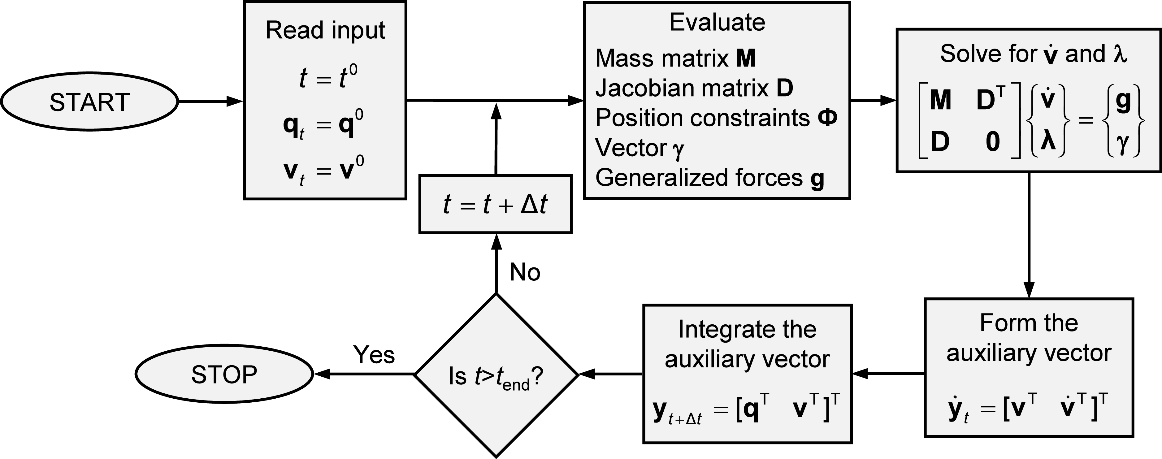
and, subsequently, the velocities and positions can be obtained through the integration process in a manner similar to the description provided above. This method for solving the dynamic equations of motion is commonly referred to as the standard Lagrange multipliers method [Reference Nikravesh64]. Fig. 4 shows a flowchart depicting the algorithm for the standard solution of the equations of motion. At t=t
0, the initial conditions on q
0 and v
0 are required to start the integration process. These values cannot be specified arbitrarily, but must satisfy the constraint equations defined by Eqs. (7) and (8). The algorithm presented in Fig. 4 can be summarized by the following steps:
-
1. Start at instant of time t 0 with given initial conditions for positions q 0 and velocities v 0.
-
2. Assemble the global mass matrix M, evaluate the Jacobian matrix D, construct the constraint equations Φ, determine the right-hand side of the accelerations γ, and calculate the force vector g.
-
3. Solve the linear set of the equations of motion (23) for a constrained multibody system in order to obtain the accelerations
$\dot{\textbf{v}}$
at instant t and the Lagrange multipliers λ. -
4. Assemble the vector
$\dot{\textbf{y}}_{t}$
containing the generalized velocities v and accelerations
$\dot{\textbf{v}}$
for instant t. -
5. Integrate numerically the v and
$\dot{\textbf{v}}$
vectors for time step t+Δt and obtain the new positions and velocities. -
6. Update the time variable, go to step 2) and proceed with the process for a new time step, until the final time of analysis is reached.


Flowchart of computational procedure for dynamic analysis of multibody systems.

The system of equations of motion (22) does not explicitly incorporate the position and velocity equations associated with the kinematic constraints, that is, Eqs. (7) and (8). Consequently, for moderate or long-time simulations, the original constraint equations may be violated due to the integration process and/or inaccurate initial conditions. Therefore, it is essential to implement methods capable of either eliminating errors in the position or velocity equations or, at a minimum, keeping such errors under control. In order to keep the constraint violations under control, the Baumgarte stabilization method is considered here [Reference Baumgarte65–Reference Khoshnazar, Dastranj, Azimi, Aghdam and Flores69]. This method permits constraints to be marginally violated before corrective actions are taken, in order to force the violation to vanish.
The objective of Baumgarte stabilization method is to replace the differential Eq. (10) by the following formulation [Reference Baumgarte65]
 \begin{equation} \ddot{\boldsymbol{\Phi }}+2\alpha \dot{\boldsymbol{\Phi }}+\beta ^{2}\boldsymbol{\Phi }=\textbf{0} \end{equation}
Equation (26) represents a differential equation for a closed-loop system in terms of kinematic constraint equations, in which the terms
 $2\alpha \dot{\boldsymbol{\Phi }}$
and
 $\beta ^{2}\boldsymbol{\Phi }$
play the role of control terms. The principle of the method is based on the damping of acceleration of constraint violation by providing feedback on the position and velocity of constraint violations [Reference Marques, Souto and Flores63], which shows open-loop and closed-loop control systems. In the open-loop systems,
 $\boldsymbol{\Phi }$
and
 $\dot{\boldsymbol{\Phi }}$
do not converge to zero if any perturbation occurs and, therefore, the system is unstable. Thus, using the Baumgarte approach, the equations of motion for a system subjected to constraints are stated in the following form
 \begin{equation} \left[\begin{array}{c@{\quad}c} \textbf{M} & \textbf{D}^{\textrm{T}}\\[4pt] \textbf{D} & \textbf{0} \end{array}\right]\left\{\begin{array}{c} \dot{\textbf{v}}\\[4pt] \unicode{x1D6CC} \end{array}\right\}=\left\{\begin{array}{c} \textbf{g}\\[4pt] \unicode{x1D6C4}-2\alpha \dot{\boldsymbol{\Phi }}-\beta ^{2}\boldsymbol{\Phi } \end{array}\right\} \end{equation}
If α and β are chosen as positive constants, the stability of the general solution of Eq. (27) is guaranteed. Baumgarte [Reference Baumgarte65] highlighted that the suitable choice of the parameters α and β is performed by numerical experiments. Hence, the Baumgarte method introduces some ambiguity in determining optimal feedback gains. The values of the parameters appear to be purely empirical, lacking a reliable method for selecting the coefficients α and β. The improper choice of these coefficients can lead to unacceptable results in the dynamic analysis of the multibody systems [Reference Flores and Nikravesh70]. The coordinate partitioning method [Reference Wehage and Haug71], the penalty approach [Reference de Jalón and Bayo72], and the augmented Lagrangian formulation [Reference Bayo and Ledesma73] are alternative methods for addressing the violation of constraints.
3. Contact interactions formulation
3.1. Contact kinematics
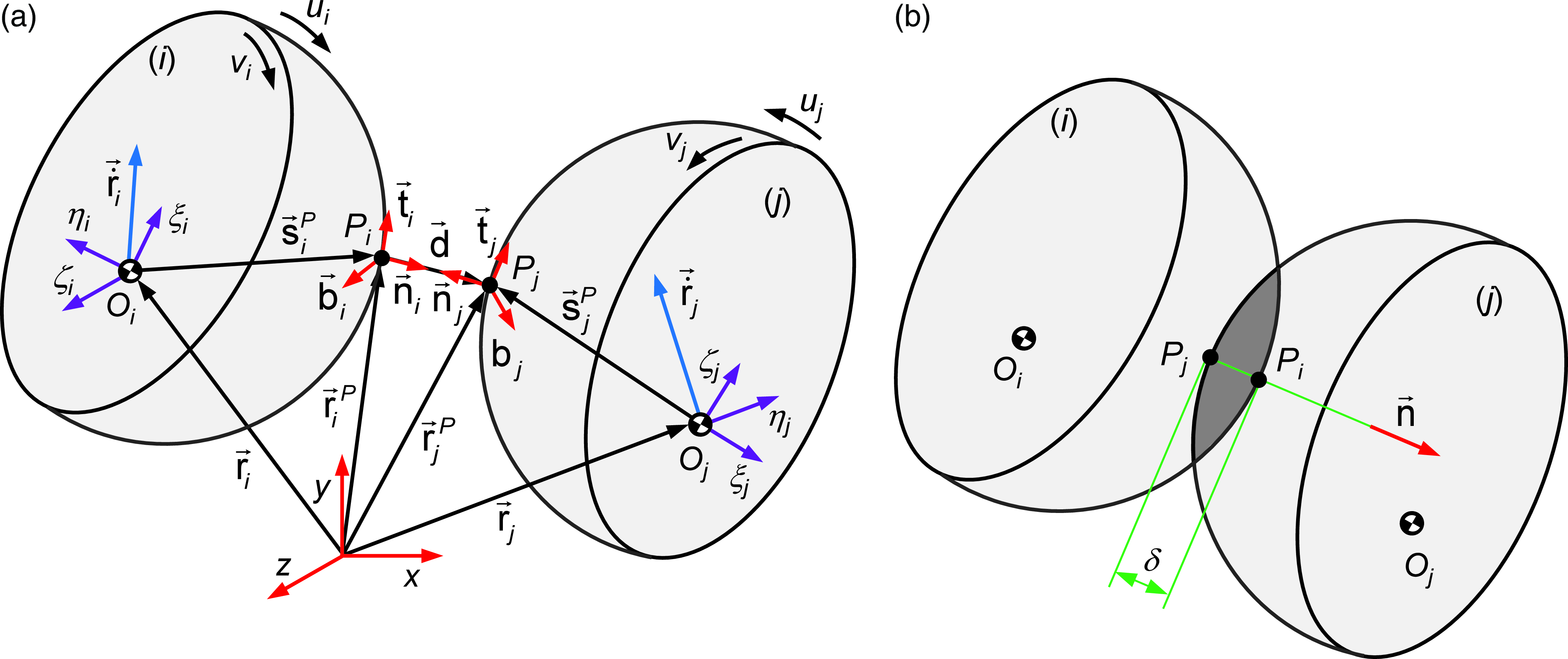
Contact kinematics deals with the determination of potential contact points, contact detection, and relative contact velocity [Reference Glocker74–Reference Flores, Ambrósio and Lankarani76]. In general, this information must be available in order to allow the evaluation of the contact forces developed during contact events. In order to better understand how these ingredients are computed in multibody dynamics, Let consider the scenario involving two rigid bodies that can potentially collide with each other, as illustrated in Fig. 5. In the situation depicted in Fig. 5a, two convex bodies i and j are in the state of separation and moving with absolute velocities
 $\dot{\textbf{r}}_{i}$
and
 $\dot{\textbf{r}}_{j}$
, respectively.
(a) Two bodies in the state of separation; (b) Two bodies in the state of contact.

The possible motion of each body within a multibody system can be quantified by assessing the distance and relative velocity of the potential contact points. Positive values of that distance represent a separation, while negative values denote relative pseudo-penetration, or indentation, of the colliding bodies. These two distinct situations are represented in Fig. 5a and 5b, respectively. The change in sign of the normal distance indicates a transition from separation to contact, or vice versa [Reference Flores and Ambrósio77]. In turn, positive values of the relative normal velocity between the potential contact points, that is, the penetration or deformation velocity, indicate that the bodies are approaching, which corresponds to the compression phase, while negative values denote that the bodies are separating, that corresponds to the restitution phase. [Reference Lankarani and Nikravesh78] The fundamental kinematic vectors of interest when modeling and analyzing contact events in the context of multibody dynamics are depicted in Fig. 5 [Reference Askari, Flores, Dabirrahmani and Appleyard79–Reference Pfeiffer81].
With regard to Fig. 5, the vector that connects the two potential contact points, P i and P j , is a gap function that can be written in the form [Reference Nikravesh56]
 \begin{equation} \textbf{d}=\textbf{r}_{j}^{P}-\textbf{r}_{i}^{P} \end{equation}
where vectors
 $\textbf{r}_{i}^{P}$
and
 $\textbf{r}_{j}^{P}$
are expressed in terms of global coordinates
 \begin{equation} \textbf{r}_{k}^{P}=\textbf{r}_{k}+\textbf{A}_{k}{\textbf{s}^{\prime}}_{k}^{P}\quad (k = i,j) \end{equation}
in which r
i
and r
j
represent the global position vectors of the bodies i and j, while
 ${\textbf{s}^{\prime}}_{i}^{P}$
and
 ${\textbf{s}^{\prime}}_{j}^{P}$
denote the local components of the potential contact points with respect to local coordinates systems. In turn, A
i
and A
j
are the rotational transformation matrices of the bodies i and j, respectively [Reference Nikravesh56].
The normal vector to the plane of contact of two surfaces, as represented in Fig. 5, can be expressed as
 \begin{equation} \textbf{n}=\frac{\textbf{d}}{d} \end{equation}
For a generic regular parametric surface defined by u-v mapping, the trihedral (t, b, n) at point s(u, v) of the surfaces is obtained using the following formulation [Reference Glocker74]
 \begin{equation} \textbf{t}=\frac{\partial \textbf{s}}{\partial u},\quad \textbf{b}=\frac{\partial \textbf{s}}{\partial v},\quad \textbf{n}=\frac{\textbf{t}\times \textbf{b}}{\left| \textbf{t}\times \textbf{b}\right| } \end{equation}
in which (u, v) are arranged such that the vector n becomes the outward normal, as in Fig. 5 [Reference Lopes, Silva, Ambrósio and Flores82–Reference Marques, Magalhães, Liu, Pombo, Flores, Ambrósio, Piotrowski and Bruni84].
The magnitude of the distance vector d, which represents a gap or penetration, can be evaluated as
 \begin{equation} d=\delta =\textbf{d}^{\textrm{T}}\textbf{n} \end{equation}
while fulfilling the conditions that the distance vector is aligned with the normal vectors of the contacting surfaces, yielding [Reference Machado, Flores and Ambrósio83]
 \begin{equation} \textbf{d}\times \textbf{n}_{i}=\textbf{0}\Leftrightarrow \left\{\begin{array}{c} \textbf{d}^{\textrm{T}}\textbf{t}_{i}=0\\[5pt] \textbf{d}^{\textrm{T}}\textbf{b}_{i}=0 \end{array}\right.,\quad\quad \textbf{d}\times \textbf{n}_{j}=\textbf{0}\Leftrightarrow \left\{\begin{array}{c} \textbf{d}^{\textrm{T}}\textbf{t}_{j}=0\\[5pt] \textbf{d}^{\textrm{T}}\textbf{b}_{j}=0 \end{array}\right. \end{equation}
where t k and b k (k=i, j) represent the tangential and binormal vectors illustrated in Fig. 5. It should be noted that the inner products between d and surfaces tangent and binormal vectors are equivalent to the cross products between d and the corresponding vectors normal to the surfaces [Reference Machado, Flores and Ambrósio83]. At this stage, it is important to mention that P i and P j are the contact points when the surfaces normal vectors n i and n j are collinear with the distance vector d. These conditions can be obtained by two cross products between vectors d and n i , and d and n j , and expressed by Eqs. (33). In fact, the geometric conditions given by Eqs. (33) constitute four nonlinear equations with four unknowns, which can be solved by utilizing an iterative numerical algorithm such as the Newton–Raphson method [Reference Nikravesh56], providing the location of the candidate contact points [Reference Machado, Flores and Ambrósio83]. Once the candidate contact points are determined, the subsequent step deals with the evaluating of their relative distance using Eq. (32). Then, it is required to verify the penetration condition, which ensures that the contact exists, that is, the candidate contact points are actual contact points [Reference Lopes, Silva, Ambrósio and Flores82–Reference Machado, Flores, Claro, Ambrósio, Silva, Completo and Lankarani86]. Once the contact points are identified, the next step involves evaluating the relative penetration between the contact bodies [Reference Flores and Ambrósio87].
The absolute velocities of the potential contact points can be expressed in terms of the global coordinate system by differentiating Eq. (29) with respect to time, yielding
 \begin{equation} \dot{\textbf{r}}_{k}^{P}=\dot{\textbf{r}}_{k}+\dot{\textbf{A}}_{k}{\textbf{s}^{\prime}}_{k}^{P} \end{equation}
in which the dot denotes the derivative with respect to time. The scalar normal and tangential velocities can be determined using the following expression
 \begin{equation} v_{\textrm{n}}=\dot{\delta }=\left(\dot{\textbf{r}}_{j}^{P}-\dot{\textbf{r}}_{i}^{P}\right)^{\textrm{T}}\textbf{n} \end{equation}
 \begin{equation} v_{\textrm{t}}=\left(\dot{\textbf{r}}_{j}^{P}-\dot{\textbf{r}}_{i}^{P}\right)^{\textrm{T}}\textbf{t} \end{equation}
This representation of the relative normal and tangential velocities is quite convenient, in the measure that there is no need to deal with the derivation of the normal unit vector because the velocities components are not directly obtained by differentiating Eq. (32). Moreover, the fully rigid body velocity kinematics can easily be applied, and the computational implementation of this method is extremely efficient. However, this approach is limited to convex rigid bodies with smooth surfaces, at least in a neighborhood of the potential contact points. In this scenario, the contact area can be reduced to a single point that may move relative to the surfaces of the bodies. This approach can be extended to more generalized contact geometries as long as a common tangent plane of the contacting bodies is uniquely defined [Reference Machado, Flores and Ambrósio83–Reference Pombo and Ambrósio90].
3.2. Contact resolution
In the context of multibody dynamics, resolving the contact involves the calculation of the normal and tangential forces developed at the contact, as well as the introduction of the resulting contact forces into the multibody system equations of motion of the system under analysis [Reference Schiehlen and Seifried91–Reference Ma, Wang, Han, Dong, Yin and Xiao98]. By and large, there are two main techniques to solve contact dynamic problems, namely, the regularized approaches (continuous methods) and the non-smooth formulations (piecewise methods) [Reference Lankarani99–Reference Piazza and Delp101]. The former methods assume that the colliding bodies are deformable at the contact zone, allowing the contact forces to be expressed as a continuous function of the local deformation. Conversely, in non-smooth techniques, the contacting bodies are assumed to be perfectly rigid, and the contact dynamics is resolved by applying unilateral constraints in order to avoid the penetration from occurring [Reference Pfeiffer and Glocker102–Reference Leine, Van Campen and Glocker104].
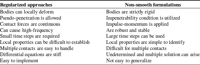
Regularized approaches are quite popular in multibody dynamics due to their computational efficiency and straightforward implementation. Nevertheless, in some circumstances, numerical problems can arise due to poorly conditioned system matrices [Reference Klisch105]. With regularized methods, there are no impulses involved in the impact process, and, therefore, there is no need for impulse dynamics computations. As a result, the transition between contact and non-contact situations can be easily handled through the system configuration and contact kinematics [Reference Lankarani and Nikravesh78]. In these methods, the contact forces incorporate spring-damper elements to prevent interpenetration. In regularized approaches, the location of the contact point does not coincide in the contacting bodies, and there exists a large number of potential contact points, being the actual contact point is the one associated with the maximum deformation. The pseudo-penetration plays a key role as it is utilized to calculate the contact reaction forces according to an appropriate constitutive law [Reference Flores, Machado, Silva and Martins92]. In general, contact force models can incorporate viscoelastic and plastic terms, along with considerations for contact kinematics and geometric properties of the contacting surfaces [Reference Ravn106, Reference Peng, Di, Qian and Chen107]. The existence of friction in the continuous methods can easily be incorporated by considering any regularized friction force model [Reference Chen and Zhang108–Reference Marques, Woliński, Wojtyra, Flores and Lankarani110].
A drawback associated with regularized approaches pertains to the estimation of contact parameters, especially when the contact geometry is complex in nature [Reference Verscheure, Sharf, Bruyninckx, Swevers and De Schutter111, Reference Roy and Carretero112]. A second difficulty of the regularized methods is the introduction of high-frequency dynamics into the system due to the existence of contact related spring-damper elements in the contacting surfaces. Therefore, when the dynamics requires the integration scheme to take small time steps, then the computational efficiency can be penalized. In methods based on non-smooth formulations, the contact points on both colliding bodies are necessarily coincident due to the unilateral constraints introduced into the system. In these methods, the relative interpenetration between the colliding bodies is not allowed, as the bodies are considered to be absolutely rigid at the contact zone [Reference Flores, Machado, Silva and Martins92, Reference Pfeiffer and Glocker113, Reference Pfeiffer114].
Assuming that the contacting bodies are absolutely rigid, in contrast to locally deformable bodies as in regularized approaches, non-smooth formulations resolve contact-impact problems using unilateral constraints to determine impulses, preventing penetration from occurring. Fundamental to non-smooth methods is the explicit formulation of unilateral constraints between colliding rigid bodies [Reference Glocker and Pfeiffer103, Reference Kwak115]. The core concept of non-smooth formulations lies in the non-penetration condition that only prevents bodies from moving toward each other and not apart, reason why this approach is called unilateral constraint [Reference Pang and Trinkle116, Reference Pfeiffer117]. For this purpose, a complementarity formulation is employed to describe the relation between contact force and gap distance at the contact point. Such unilateral constraint does not permit the interpenetration of the two colliding bodies and ensures that either contact force or gap distance is null. This means that, when the gap distance is positive (open or inactive contact), the corresponding contact force is null. Conversely, when the contact force is positive (closed or active contact), the gap distance is null [Reference Pfeiffer and Glocker102]. Thus, this formulation leads to a complementarity problem, serving as the framework that enables the treatment of multibody systems with unilateral constraints [Reference Signorini118, Reference Trinkle, Tzitzouris and Pang119].
The numerical issues associated with regularized approaches may not arise in non-smooth methods, but they introduce different challenges and requirements [Reference Studer120, Reference Klisch121]. For instance, the existence of a unique solution is not ensured, because in some cases, the system can be undetermined or have multiple solutions [Reference Leine, Brogliato and Nijmeijer122–Reference Pfeiffer124]. In general, commercial multibody codes equipped with collision and dry friction features handle the non-smooth nature of the problem through an ad hoc regularized approach. In fact, they use continuous models to prevent undesired interpenetration between bodies, which can ultimately lead to some numerical and computational difficulties.
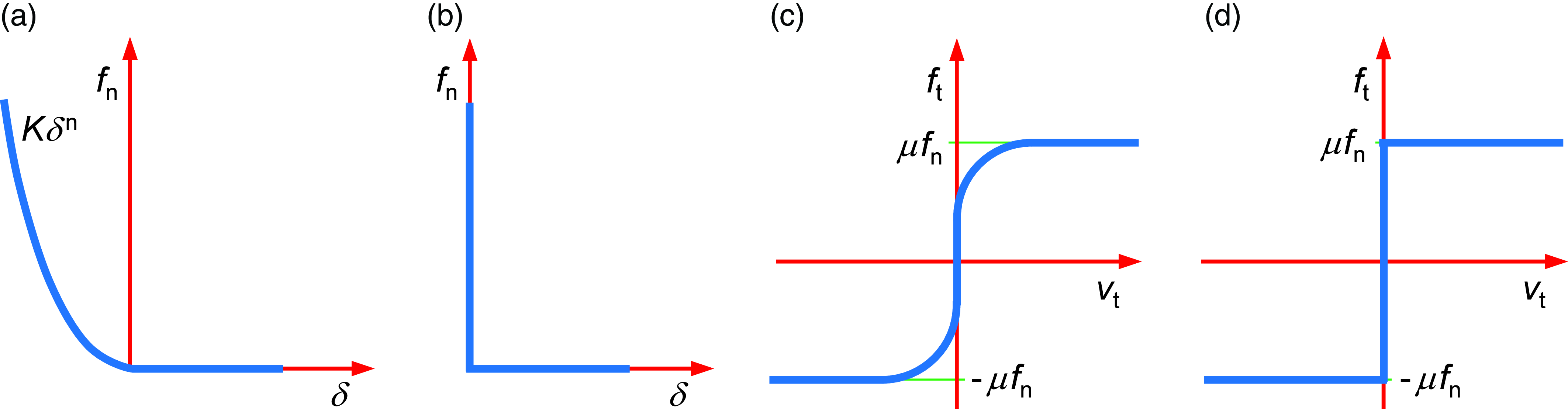
Fig. 6 shows the graphical representation of the normal and tangential contact forces for the regularized approaches and non-smooth formulations. both the regularized approaches and the non-smooth methods employed to address contact-impact events within the framework of multibody dynamics have inherent advantages and disadvantages. Regardless, none of these briefly characterized techniques can be unequivocally identified as superior. A particular multibody system with collision events might easily be described by one method, nevertheless, this does not automatically imply a general predominance of that formulation in all multibody applications [Reference Kraus and Kumar125–Reference Pazouki, Kwarta, Williams, Likos, Serban, Jayakumar and Negrut128].
Table I lists the key characteristics associated with regularized and non-smooth methods, allowing for a comparative analysis. One critical issue related to frictional contact problems, affecting the accuracy and fidelity of the results obtained, pertains to the discretization or modeling process of the mechanical system under analysis. If the problem is well discretized, in general, both regularized and non-smooth techniques are effective in addressing frictional problems. In any case, the evaluation of the geometry of contact is the same, regardless of the chosen technique used to model the contact interaction between the colliding bodies, whether it be regularized approaches or non-smooth formulations [Reference Melanz, Fang, Jayakumar and Negrut129, Reference Khadiv, Moosavian, Yousefi-Koma, Sadedel, Ehsani-Seresht and Mansouri130].
Contact mechanics in multibody systems deals with the modeling and analysis of deformation of solid parts when they contact or collision with each other. The specific case of frictional contact mechanics involves the analysis of collisions that include frictional phenomena [Reference Johnson131]. It is noteworthy that contact mechanics plays a ubiquitous role in many multibody systems applications, and in most of the cases, their behavior and performance are strongly affected by the modeling process for contact-impact events [Reference Jian, Hu, Fang, Zhou and Xia132–Reference Wan, Liu, Song, Zhou, Ma and Tong134]. Contact dynamics, focused on analyzing the motion of multibody systems experiencing collisions, remains one of the most challenging domains in both science and engineering [Reference Kildashti, Dong and Samali135–Reference Wang, Tian and Hu141].
The subject of contact mechanics and its applications in multibody dynamics had not been developed until the past few decades. Wittenberg [Reference Wittenberg142], Wehage [Reference Wehage143], and Khulief et al. [Reference Khulief, Haug and Shabana144] utilized a piecewise approach to handle impact events in multibody systems. In this discontinuous technique, the resolution of the equations of motion is halted at the instant of collision, where an impulse-momentum balance is performed to obtain the rebound velocities. The resolution of the equations of motion is then resumed with the updated velocities until a new collision takes place. Wehage and Haug [Reference Wehage and Haug145] utilized the Newton’s impact law together with piecewise contact approach to discuss contact problems in constrained multibody mechanical systems. Khulief and Shabana [Reference Khulief and Shabana146] formulated the generalized impulse-momentum balance equations to analyze impacts in multibody systems.
Comparison between regularized and non-smooth methods to deal with contact problems.

(a) Regularized normal contact force model; (b) Non-smooth normal contact force model; (c) Regularized tangential contact force model; (d) Non-smooth tangential contact force model.

The problem of friction in multibody dynamics was investigated by Khulief [Reference Khulief147]. Battle and Condomines [Reference Batlle and Condomines148] utilized a Lagrangian formulation and impulsive drivers to maintain the continuity of a set of generalized velocities during the impact process to model collisions in dynamical systems. A similar analysis was conducted by Lankarani and Nikravesh [Reference Lankarani and Nikravesh149] to treat multibody systems with intermittent motion. These authors demonstrated that the numerical resolution of the canonical equations of motion is quite efficient and stable. Haug et al. [Reference Haug, Wu and Yang150] formulated and solved the equations of motion using the Lagrange multipliers technique. The Newton’s hypothesis and Coulomb’s friction law were considered to represent the impacts. The problem was replicated by Wang and Kumar [Reference Wang and Kumar151] and Anitescu et al. [Reference Anitescu, Cremer and Potra152], solution of which was obtained as a quadratic programing problem.
Over the past decades, the multibody dynamics community has exhibited an increasing interest in the resolution of the problems related to collisions between mechanical components. Actual examples of multibody mechanical systems in which contact–impact interactions play a crucial role are grasping and fingers contacts [Reference Ghafoor, Dai and Duffy153–Reference Hao and Nichols157], robotics and walking machines [Reference Marhefka and Orin158–Reference Liu and Ben-Tzvi161], vehicle and railway subsystems [Reference Ambrósio and Verissimo162–Reference Vollebregt171], biosystems and biomechatronics [Reference Modenese and Phillips172–Reference Mouzo, Michaud, Lugris and Cuadrado178], machines and mechanisms [Reference Schwab, Meijaard and Meijers179–Reference Ohno and Takeda187], granular media and powder technologies [Reference Kuwabara and Kono188–Reference Melanz, Jayakumar and Negrut192], toys models [Reference Turner193–Reference Galvez, Cosimo, Cavalieri, Cardona and Brüls201], civil structures [Reference Jankowski202–Reference Beatini, Royer-Carfagni and Tasora211], sounds and musical instruments [Reference Avanzini, Serafin and Rocchesso212–Reference Timmermansa, Ceulemans and Fisette217], and fruit transport and handling [Reference Dintwa, Van Zeebroeck, Tijskens and Ramon218–Reference Zhang, Wang, Wang, Fu and Yang223], just to mention some examples under the umbrella of dynamical systems.
The topic of contact-impact problems in dynamical systems has received a great deal of attention in the past decades and still remains an active area of research that led to the establishment of important works and even the publication of relevant textbooks devoted to this theme, such as the ones by Pfeiffer and Glocker [Reference Pfeiffer and Glocker102], Glocker [Reference Glocker224], Leine and Nijmeijer [Reference Leine and Nijmeijer225], Pfeiffer [Reference Pfeiffer226], Acary and Brogliato [Reference Acary and Brogliato227], and Flores and Lankarani [Reference Flores and Lankarani228]. Additionally, the interested reader is also referred to the following seminal works on contact problems [Reference Flores, Ambrósio and Lankarani76, Reference Flores93, Reference Pfeiffer114, Reference Gilardi and Sharf229–Reference Stewart231].
Finally, challenges and future directions for research under the framework of contact mechanics in multibody dynamics may include: the identification and estimation of the contact parameters for complex scenarios; the development of benchmark problems to assess the suitability of the existing techniques to handle contact-impact events; the analysis of contact problems with very large contact areas; the study of contacts with very flexible bodies; and the development of techniques to accelerate the contact detection with multiple potential contacts.
4. Continuous contact force models
4.1. Normal force models
The simplest contact force model is associated with Hooke’s theory, and it can be applied when contact is active. This regularized force model incorporates a linear spring to mimic the contact interaction and can be written as [Reference Shigley and Mischke232]
 \begin{equation} f_{\textrm{n}}=k\delta \end{equation}
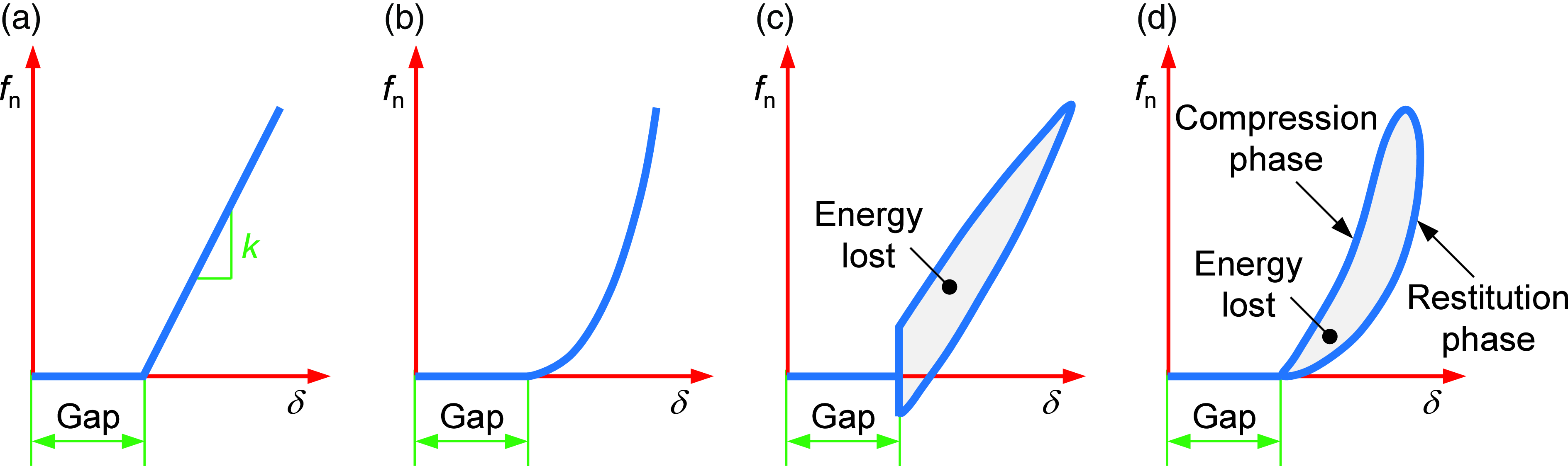
in which k represents the spring stiffness related to the contact materials, and δ denotes the penetration between the contacting surfaces (32). Fig. 7a shows the representation of the plot force–penetration for the Hooke contact force model. This approach is quite simple, but does not account for any kind of energy dissipation during the contact process.
Force-penetration relations for different contact force models: (a) Hooke’s law; (b) Hertz’s law; (c) Kelvin-Voigt approach; (d) Hunt and Crossley contact force model. The gap illustrated in these representations is the distance when the potential contact bodies are in a separation status.

A superior contact force model was formulated by Hertz, introducing a nonlinear relation between force and penetration [Reference Hertz233]
 \begin{equation} f_{\textrm{n}}=K\delta ^{n} \end{equation}
where the nonlinear exponent, n, is typically equal to 3/2. Fig. 7b depicts the force–penetration relation for the nonlinear Hertz’s law. The Hertz contact force model is incapable of predicting any energy dissipation associated with contact-impact events. The value of the contact stiffness parameter, K, can be evaluated analytically as function of the material and geometric properties of the contacting surfaces. Thus, based on the Hertz contact theory, the contact stiffness for two solid and isotropic spheres in contact can be established as
 \begin{equation} K=\frac{4}{3\left(\sigma _{i}+\sigma _{j}\right)}\sqrt{\frac{R_{i}R_{j}}{R_{i}+R_{j}}} \end{equation}
where the material properties, σ 1 and σ 2, are defined as
 \begin{equation} \sigma _{k}=\frac{1-\nu _{k}^{2}}{E_{k}}\quad (k = i, j) \end{equation}
and the quantities ν k and E k are, respectively, the Poisson’s ratio and Young’s modulus of each sphere in contact. It should be noted that, by definition, the radius is positive for convex surfaces and negative for concave surfaces [Reference Marques, Souto and Flores63].
The first contact force model that accommodates energy dissipation in collisions is the Kelvin–Voigt approach, which combines a linear spring with a linear damper to represent the contact forces as [Reference Goldsmith234]
 \begin{equation} f_{\textrm{n}}=K\delta +D\dot{\delta } \end{equation}
where the first parcel denotes the elastic force term, and the second parcel denotes the dissipative force component, in which D represents the damping coefficient, and
 $\dot{\delta }$
is the normal relative velocity of the contacting bodies (35). Fig. 7c illustrates the force–penetration relation for the linear Kelvin–Voigt contact force model. It is important to mention that this approach displays discontinuities at the initiation and termination of the contact process. Indeed, the damping term introduces finite forces when the penetration is zero, which is not acceptable from a physical point of view. Furthermore, at the end of contact, the Kelvin–Voigt force model produces negative forces, which are not physically correct, as bodies involved in a collision cannot attract each other.
Hunt and Crossley proposed a contact force model that incorporates a nonlinear spring and a nonlinear damper in parallel to simulate the contact interaction. This force model can be formulated as [Reference Hunt and Crossley235]
 \begin{equation} f_{\textrm{n}}=K\delta ^{n}\left[1+\frac{3\left(1-c_{\textrm{r}}\right)}{2}\frac{\dot{\delta }}{\dot{\delta }^{\left(-\right)}}\right] \end{equation}
where the first term represents the nonlinear elastic Hertz’s law, and the second term is the dissipative parcel, being c
r the coefficient of restitution, and
 $\dot{\delta }^{(-)}$
is the normal contact velocity at the initial instant of impact. Fig. 7d illustrates the force–penetration evolution for the Hunt and Crossley contact force model, revealing the compression and restitution phases of an impact. In this diagram, the area of the hysteresis loop represents the amount of energy lost during the impact process. The Hunt and Crossley force model does not exhibit any discontinuity at the beginning or ending of the collision.
The most widely used contact force model in multibody dynamics is the one proposed by Lankarani and Nikravesh [Reference Tang, Li, Zhang, Zhang and Yu53]. It was developed based on the Hertzian theory and incorporates the damping approach by Hunt and Crossley. Lankarani and Nikravesh contact force model can be expressed as
 \begin{equation} f_{\textrm{n}}=K\delta ^{n}\left[1+\frac{3\left(1-c_{\textrm{r}}^{2}\right)}{4}\frac{\dot{\delta }}{\dot{\delta }^{\left(-\right)}}\right] \end{equation}
This model is valid for collisions with high values of the coefficient of restitution, making it applicable to elastic impacts. The contact force model presented by Lankarani and Nikravesh has been utilized in many areas of science and engineering.
Flores et al. [Reference Flores, Machado, Silva and Martins92] presented a contact force model that is applicable to the entire range of possible values for the coefficient of restitution, which is given by
 \begin{equation} f_{\textrm{n}}=K\delta ^{n}\left[1+\frac{8\left(1-c_{\textrm{r}}\right)}{5c_{\textrm{r}}}\frac{\dot{\delta }}{\dot{\delta }^{\left(-\right)}}\right] \end{equation}
he use of the contact force models (43) and (44) results in a similar evolution of the force–penetration diagram as in the case of the Hunt and Crossley approach (see Fig. 7d). For low values of the coefficient of restitution, the hysteresis loop for the Flores et al. contact force model is larger. It must be noticed that the force models (42)-(44) can exhibit some limitations when the contacts are too long, and when the velocity ratio
 $\dot{\delta }/\dot{\delta }^{(-)}$
becomes significantly less than –1 [Reference Ambrósio236, Reference Marques, Magalhães, Pombo, Ambrósio and Flores237]. Over the past few years, a significant number of contact force models have been presented in the literature. For detailed information, the interested reader is referred to the following references [Reference Liu, Cheng, Li and Wei238–Reference Corral, Moreno, García and Castejón240].
4.2. Friction force models
Friction is the interaction between two objects as one rubs against the other. In other words, friction is the resistance an object experiences when moving over another. In fact, when two contacting bodies move or tend to move relative to each other, tangential forces are developed at the surfaces of interaction. In multibody dynamics, the presence of friction on contact surfaces complicates and adds complexity to contact problems. Friction introduces different contact behaviors, encompassing both sticking and sliding. Stiction, occurring when the relative tangential velocity between two contacting surfaces approaches zero, is a phenomenon that the friction model employed in dynamic analysis must accurately predict [Reference Ahmed, Lankarani and Pereira241].
Da Vinci was a pioneer in the study of friction, particularly in terms of the required weight needed to be applied to different objects placed on horizontal and inclined planes to initiate their motion [Reference Hutchings242]. Based on experimental observations, da Vinci formulated two fundamental laws of friction. The first law states that the friction generated by the same weight will exhibit equal resistance at the beginning of its movement, even if the contact area varies in width and length. The second law of friction posits that friction produces twice the effect when the weight is doubled. Amontons developed his experimental apparatus to investigate friction and rediscovered the laws of friction formulated by da Vinci [Reference Amontons243]. According to Amontons, the friction law can be expressed as: (i) the friction force is independent of the apparent area of contact between the two surfaces in contact and (ii) the force of friction acting between two sliding surfaces is proportional to the load pressing the surfaces. Coulomb, arguably the most renowned name in the field of friction, published laws of friction, referring to the work of Amontons [Reference Coulomb244]. Coulomb extended Amontons’ friction laws to a modern conceptual framework, and these laws are still used today. The two basic Coulomb’s friction laws can be stated as (i) the friction force is independent of the nominal area of contact and (ii) the friction is proportional to the normal contact force.
The dry Coulomb’s friction law can be expressed as
 \begin{equation} f_{\textrm{t}}=\left\{\begin{array}{l@{\quad}l@{\quad}l} \left[-\mu _{\textrm{k}}f_{\textrm{n}},\,\mu _{\textrm{k}}f_{\textrm{n}}\right] & & \textrm{if}\,\left\| \textbf{v}_{\textrm{t}}\right\| =0\\[5pt] \mu _{\textrm{k}}f_{\textrm{n}}\textrm{sgn}\left(\textbf{v}_{\textrm{t}}\right) & & \textrm{if}\,\left\| \textbf{v}_{\textrm{t}}\right\| \neq 0 \end{array}\right. \end{equation}
where
 \begin{equation} \textrm{sgn}\left(\textbf{v}_{\textrm{t}}\right)=\left\{\begin{array}{l@{\quad}l@{\quad}l} \dfrac{\textbf{v}_{\textrm{t}}}{\left\| \textbf{v}_{\textrm{t}}\right\| } & & \textrm{if}\,\left\| \textbf{v}_{\textrm{t}}\right\| \neq 0\\[9pt] 0 & & \textrm{if}\,\left\| \textbf{v}_{\textrm{t}}\right\| =0 \end{array}\right. \end{equation}
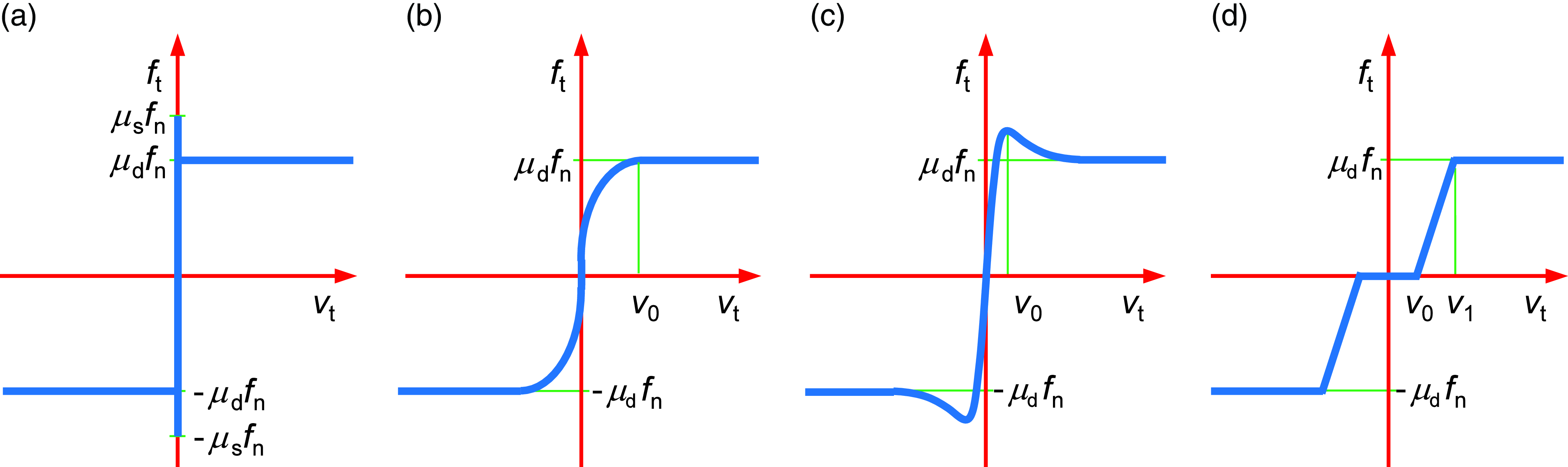
in which μ k is the kinetic coefficient of friction, f n is the normal contact force, and v t is the tangential velocity vector. The first branch of Eq. (45) is referred to as static or stiction friction, while the second branch is named dynamic or sliding friction. Fig. 8a shows the representation of the Coulomb’s friction force model. It is important to note that this friction law poses some numerical challenges in terms of computational implementation in multibody simulations when the tangential relative velocity is zero.
Representation of several friction force models: (a) Coulomb’s friction law; (b) Threlfall friction force model; (c) Bengisu and Akay friction force model; (d) Ambrósio friction force model.

Threlfall [Reference Threlfall245] introduced a regularized friction force model that avoids discontinuities, as it is evident from the observation of diagram in Fig. 8b. The Threlfall friction force model can be written as
 \begin{equation} f_{\textrm{t}}=\left\{\begin{array}{l@{\quad}l@{\quad}l} \mu _{\textrm{k}}f_{\textrm{n}}\left(1-\textrm{e}^{-3\frac{\left\| \textbf{v}_{\textrm{t}}\right\| }{v_{0}}}\right)\textrm{sgn}\left(\textbf{v}_{\textrm{t}}\right) & & \textrm{if}\,v_{0}\leq \left\| \textbf{v}_{\textrm{t}}\right\| \leq v_{0}\\[5pt] 0.95\mu _{\textrm{k}}f_{\textrm{n}}\textrm{sgn}\left(\textbf{v}_{\textrm{t}}\right) & & \textrm{if}\,\left\| \textbf{v}_{\textrm{t}}\right\| \gt v_{0} \end{array}\right. \end{equation}
in which v 0 represents the tolerance sliding velocity.
Bengisu and Akay [Reference Bengisu and Akay246] introduced a static friction model in order to capture the stiction behavior of friction. An enhanced version proposed by Marques et al. [Reference Marques, Flores, Pimenta Claro and Lankarani30] is expressed by piecewise function as
 \begin{equation} f_{\textrm{t}}=\left\{\begin{array}{c@{\quad}c} \left[-\dfrac{\mu _{\textrm{s}}f_{\textrm{n}}}{v_{0}^{2}}\left(\left\| \textbf{v}_{\textrm{t}}\right\| -v_{0}\right)^{2}+\mu _{\textrm{s}}f_{\textrm{n}}\right]\textrm{sgn}\left(\textbf{v}_{\textrm{t}}\right) & \quad \textrm{if}\,\left\| \textbf{v}_{\textrm{t}}\right\| \lt v_{0}\\[15pt] \left[\mu _{\textrm{k}}f_{\textrm{n}}+\left(\mu _{\textrm{s}}f_{\textrm{n}}-\mu _{\textrm{k}}f_{\textrm{n}}\right)\textrm{e}^{-\xi \left(\left\| \textbf{v}_{\textrm{t}}\right\| -v_{0}\right)}\right]\textrm{sgn}\left(\textbf{v}_{\textrm{t}}\right) & \quad \textrm{if}\,\left\| \textbf{v}_{\textrm{t}}\right\| \geq v_{0} \end{array}\right. \end{equation}
where μ s is the static friction coefficient and ξ is a positive parameter related to the negative slope of the sliding state associated with the Stribeck effect. Fig. 8c illustrates the evolution of the Bengisu and Akay friction force model.
Ambrósio [Reference Ambrósio247] suggested another regularized approach for Coulomb’s law, which incorporates a ramp to overcome numerical difficulties. This friction force model can be expressed as
 \begin{equation} f_{\textrm{t}}=c_{\textrm{d}}\mu _{\textrm{k}}f_{\textrm{n}}\textrm{sgn}\left(\textbf{v}_{\textrm{t}}\right) \end{equation}
with
 \begin{equation} c_{\textrm{d}}=\left\{\begin{array}{c@{\quad}c} 0 & \quad \textrm{if}\,\left\| \textbf{v}_{\textrm{t}}\right\| \lt v_{0}\\[5pt] \dfrac{\left\| \textbf{v}_{\textrm{t}}\right\| -v_{0}}{v_{1}-v_{0}} & \quad \textrm{if}\,v_{0}\leq \left\| \textbf{v}_{\textrm{t}}\right\| \leq v_{1}\\[10pt] 1 & \quad \textrm{if}\,\left\| \textbf{v}_{\textrm{t}}\right\| \gt v_{1} \end{array}\right. \end{equation}
in which the dynamic correction factor, c d, prevents the friction force from changing direction for almost null values of the tangential relative velocity. Fig. 8d shows Ambrósio’s friction approach.
The utilization of the friction models (47), (48), and (49) offers the advantage of enabling the numerical stabilization of the integration algorithm used in resolving the equations of motion for constrained multibody systems. These approaches do not account for stiction. Therefore, several alternative friction force models have been proposed over the past few decades. Interested readers are referred to the following references for more detailed information [Reference Dahl248–Reference Specker, Buchholz and Dietmayer254].
Most of the aforementioned friction force models smooth Coulomb’s law, making them continuous or regularized solutions. This characteristic enables a stable and efficient resolution of the equations of motion for multibody mechanical systems. It should be noted that a straightforward and clear rule of thumb for selecting appropriate values for the parameters involved in the described friction models is not readily available. Typically, their choice relies on the trial-and-error method.
5. Examples of application
5.1. Hexapod robotic system – ATHENA
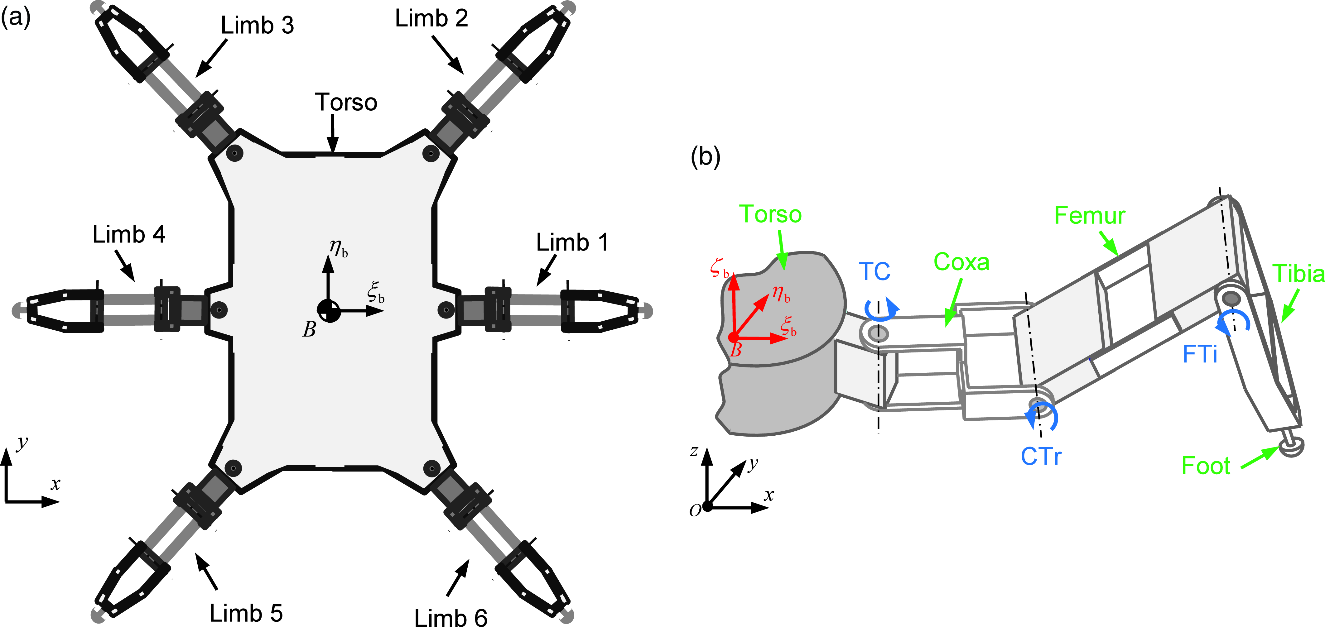
The first example presented here is the hexapod robotic system named ATHENA, composed of six legs arranged symmetrically around the main body. A representation of the multibody system is depicted in Fig. 9a. Each limb included four bodies and has three degrees of freedom. The nomenclature for the leg’s segments and joints is presented in Fig. 9b. To examine the dynamic response of the hexapod robot, it is necessary to analyze the robot as a multibody system. Thus, the multibody model of the hexapod robot is described by 25 rigid bodies and 24 joints. In terms of joints’ description, 18 of them are considered active with revolute motion, while the remaining six joints fix the feet to the tibia segments [Reference Coelho, Dias, Lopes, Ribeiro and Flores255].
Hexapod robot multibody model: (a) Multibody subsystems; (b) Representation of each limb’s multibody model: green identifies the system’s rigid bodies, and blue represents the active joints.

For the dynamic analysis of the hexapod robotic system, specific trajectories are prescribed for all legs. For that, driving constraints are applied to each driven revolute joint. The locomotion of the hexapod robot is examined by utilizing the equation of motion derived from the multibody model. In this study, the hexapod robot adopts a tripod gait and walks across a regular surface for approximately 6 s. Each gait cycle takes 2 s to be completed. Each gait cycle takes 2 s to be completed. The limbs’ trajectory is defined by a cubic spline that combines discrete points of the foot for the swing and the stance phases. The contacts between the robot’s feet and the ground are modeled using the regularized approaches described in Section 4, namely those given by Eqs. (43) and (48). For the numerical resolution of the equations of motion, the Baumgarte stabilization method is utilized together with an integrator with both variable time step and order ability. The dynamic response of the hexapod system is illustrated by the diagrams showing the position and velocity of the torso, as depicted in Figs. 10a and 10b, respectively. It can be observed that the hexapod’s torso moves in the longitudinal direction, and the height of the body remains stable (see Fig. 10a). In turn, the torso exhibits linear velocity, and the motion in the lateral and vertical directions is consistent throughout the computational simulations, which ultimately demonstrates the stability of the gait.
Global motion of the hexapod robot: (a) Position of the torso in the lateral, longitudinal and vertical directions; (b) Velocity of the torso in the lateral, longitudinal and vertical directions.

As expected, the contact forces developed between the feet and the ground influence the motion of the hexapod’s limbs. Figs. 11a-f shows the plots of the normal contact forces produced during the hexapod motion. Overall, the hexapod robot produces normal contact forces of similar magnitude for all its feet. Given the model’s type of gait, limbs 1, 3, and 5 must contact the ground at the same time, while the remaining limbs are in the swing phase. In the transition of the gait phases, the contact force’s magnitude increases. Limb 1 supports the right-side of the hexapod robot’s torso, whereas limbs 2 and 6 are in the swing phase. Thus, there is an increase of the contact force in the beginning of the stance phase, as Fig. 11a shows. The third and fifth limbs are in the model’s left side. In the stance phase, the rear limb initially supports most of the weight because of the hexapod robot’s motion. Furthermore, the distribution of weight gradually changes, and by the end of the stance phase, the normal contact force is higher in the third limb, as shown in the plots of Figs. 11c and e depict. This indicates that contact in the two feet occurs simultaneously. Then, the fifth limb’s normal force at the contact event has a higher magnitude, which is caused by an actuation delay of the third limb. Considering that the actuation of limbs 2, 4, and 6 is identical, a similar behavior is observed (see Figs. 11b, d and f).
Plots of the hexapod robot’s normal contact forces: (a-f) Contact forces for limb 1 to 6.

Considering that the same contact model is applied to all limbs, the relation between the penetration depth and the normal contact force for the second limb is presented in Fig. 12. The plot displays only the initial impacts of the second limb. It can be observed that the normal contact force’s decreases during the impact events due to energy dissipation. In the stance phase, the feet are in contact with the ground. Therefore, with the time’s progression, the relation between the contact force and the relative penetration converges to a certain quantity. Due to less energy dissipation associated with the restitution phase, more energy rebounds are observed, leading to a higher variability of the normal contact force.
Normal contact force versus penetration of the first impacts for the second limb.

The motion of the hexapod robot is also influenced by the frictional forces developed between the feet and the ground. In order to better understand how friction evolves during the hexapod’s motion, the ratio between the normal and friction forces of each foot is presented in Figs. 13a-f. In each gait cycle, the ratio between the friction and the normal forces does not exceed the kinetic coefficient of friction. Thus, it is considered that there is no slippage of the feet in the stance phase and the model’s motion is validated. Since the friction force is directly related to the normal force, the variation of the ratio during each gait cycle is affected by the same phenomena in terms of the trajectory of the limbs.
Plots of the hexapod robot’s tangential contact forces: (a-f) Friction forces for limb 1 to 6.

5.2. Mobile manipulator robot – CHARMIE
The CHARMIE [Reference Gonçalves, Ribeiro, Ribeiro, Lopes and Flores256] is a human-inspired mobile manipulator robot designed to interact with humans, specifically assisting with domestic tasks. The robot is divided into five main systems: (i) a locomotive system using four omnidirectional wheels; (ii) an independent suspension system; (iii) an articulated hip mechanism; (iv) two 7-DOF manipulator arms; and (v) the robot’s head. This robot is modelled as a multibody system with 45 bodies and 54 joints (Fig. 14), assembled in a configuration which results in a total of 36 degrees of freedom (including the six degrees of freedom that allow the robot to navigate through space). The key bodies in CHARMIE’s structure are 1 the base, 2 the hip, 3 the trunk, 4a-10a the right arm, 4b-10b the left arm, and 4c-6c the robot’s head.
Kinematic diagram showcasing the bodies and degrees of freedom of the CHARMIE robot.

The CHARMIE multibody model is represented by a kinematic tree (Fig. 15), where the branches are treated as serial systems using recursive algorithms. First, the forward kinematics of each link are modeled from the base to the end-effector. Subsequently, a Newton–Euler formulation is employed to perform the dynamic analysis. The closed and overconstrained loops (connecting the link pairs 1-2 and 2-3) necessitated additional formulation to solve both the kinematics and dynamics.
Kinematic tree representing CHARMIE’s multibody system.

The interaction of the CHARMIE system with its surroundings can be analyzed using forward dynamics. These interactions are collisions with obstacles, the wheel-floor contact dynamics, and the manipulation of intended objects. The multibody system has been implemented into Python [Reference Gonçalves, Ribeiro, Ribeiro, Lopes and Flores18]. The numpy library was used to assist in solving mathematical operations, while the matplotlib library assisted in generating the graphical outputs of the simulator (Fig. 16). The resulting code is hardware-independent and can be implemented into the robot’s embedded computer.
Simulation environment for testing the CHARMIE robot.

The equations of motion describing the behavior of the robot’s bodies are computed to create the simulator. These equations take as inputs the physical properties of the bodies (mass, inertia, and geometry) and joints (orientation, joint type, and joint placement). The simulation environment incorporates the multibody model of the robot, a flat floor plane, two tables with which the robot can collide, and a cylindrical body representing a can which will be the target of manipulation of the robot. The position of the robot, the tables, and the cylindrical body can be randomized for the training of a neural network solution. The results derived from both the kinematic and dynamic analyses of the developed approach undergo validation through a comparison with outcomes generated by commercial software, namely the Visual Nastran 4D. The same motion was tested for both simulation environments. As it was expected, both methodologies give similar outcomes, as it is visible in the plots of Figs. 17 and 18, which show a very good agreement between the overall results obtained with present approach and commercial software. Furthermore, the simulator’s computational efficiency was evaluated utilizing four different models: a 2-DOF Arm, a 4-DOF Arm, a 6-DOF Arm, and the CHARMIE Robot. These models were simulated, without a graphical interface, in PyCharm on a computer with an AMD Ryzen 5 5600X 6-Core Processor 3.70 GHz, efficiency of which is presented in Table II.
Comparison of the computational effort for 1000 time-steps of simulation for different models.

Comparison between the results for the forward kinematics of the robot’s end-effector for the simulator utilized in the present study and a commercial software (Visual nastran 4D).

Comparison between the results for the inverse dynamics of the robot’s end-effector for the simulator utilized in the present study and a commercial software (Visual nastran 4D).

6. Concluding remarks
In this paper, the important problem of modeling and simulation multibody systems in particular field of robotics is revisited. Special attention was given to the cases that involve contact-impact scenarios in their dynamic response. Multibody dynamics methodologies are quite effective tools to model and simulate robotic systems that experience contact conditions with the surrounding environment, namely those that occur between feet and ground in robots’ locomotion. When dealing with these challenging problems, it is essential to properly address the large displacement of the robot bodies, as well as the demanding aspects associated with the numerical and computational implementation of the collisions in dynamical systems. Moreover, a general methodology based on the Newton–Euler method was used to represent the motion of robotic systems. The fundamental kinematic and dynamic characteristics necessary to derive the equations of motion were outlined. Additionally, a numerical procedure suitable for solving these equations was presented. The demanding issue of modeling contact-impact events in dynamical systems encompasses two primary tasks: contact detection and contact resolution.
To accurately model collisions, the contact kinematic properties are established based on the geometry of the contacting bodies, facilitating the contact detection task. Subsequently, continuous contact force models are employed to represent contact dynamics, encompassing both normal and tangential contact directions. In the realm of normal contact forces, this discussion delves into regularized models rooted in the established Hertzian contact theory, augmented with a dissipative term. Similarly, various regularized friction force models, based on Coulomb’s friction law, were scrutinized. These models prove to be highly effective, offering a balance between accuracy and stability in resolving the equations of motion. Two illustrative examples of applications within the framework of multibody systems methodologies were discussed. These examples serve to emphasize the essential aspects associated with the modeling of contact-impact events in robotics. Particular attention was given to the dynamic behavior of the systems, focusing on aspects of performance and stability.
Future developments in the realm of multibody dynamics for robotic systems with collisions may encompass: (i) identification and estimation of contact parameters by exploring methods to identify and estimate contact parameters in intricate scenarios, enhancing the understanding of contact interactions; (ii) benchmark problem development by creating benchmark problems to evaluate the effectiveness of existing techniques in handling contact-impact events; (iii) analysis of large contact areas by investigating contact problems with extensive contact areas, addressing challenges that arise when dealing with such complex scenarios; (iv) accelerating contact detection by developing techniques to accelerate the contact detection process, especially in situations involving multiple potential contacts. Absolutely, addressing these aspects can indeed contribute significantly to both the efficiency of simulations and real-time applications, as well as foster advancements in methodologies. By enhancing the ability to identify and estimate contact parameters, creating benchmark problems, tackling large contact areas, and accelerating contact detection, we can refine and optimize the modeling and simulation of robotic systems with collisions. This, in turn, will positively influence the development and performance of robotic technologies across diverse applications.
Author contributions
M.R. Silva, F. Novais, and P. Flores conceived and designed the study. J. Coelho, F. Gonçalves, and P. Flores developed methodology, J. Coelho and F. Gonçalves implemented solutions, J. Coelho, F. Gonçalves, and P. Flores analyzed results. M.R. Silva, J. Coelho, F. Gonçalves, F. Novais, and P. Flores wrote article.
Financial support
The first, second and third authors acknowledge the support from Portuguese Foundation for Science and Technology (FCT) through the PhD grants (2021.04840.BD, SFRH/BD/145818/2019, and SFRH/BD/145993/2019), with funds from the Portuguese Ministry of Science, Technology and Higher Education and the European Social Fund through the Programa Operacional Regional Norte. This work has been supported by the Portuguese Foundation for Science and Technology, under the national support to RD units grant, with the reference project UIDB/04436/2020 and UIDP/04436/2020.
Competing interests
The authors declare no competing interests exist.
Ethical approval
Not applicable.