1. Introduction
As a kind of clean and intelligent vehicle in the ocean, the advantages of unmanned sailboats are obvious in long-distance transportation, marine data collection and environmental monitoring (Neal, Reference Neal2006). Unmanned sailboats not only can save human and natural resources, but are also free from carrying fuel, and can be used for remote monitoring and transportation at sea (Plumet et al., Reference Plumet, Petres, Romero-Ramirez, Gas and Ieng2015). Therefore, the research prospects of unmanned sailboats are very attractive. In the 1990s, researchers began to study unmanned sailboats extensively. After decades of research, the development of unmanned sailboats has made great progress (Elkaim, Reference Elkaim2006). The International Robotics Sailing Conference and World Robotics Sailing Championship (IRSC/WRSC) provide a reliable academic exchange platform for scholars and enthusiasts around the world, and have greatly promoted the development of unmanned sailboats (Rynne and Von Ellenrieder, Reference Rynne and Von Ellenrieder2009). The progress of research on unmanned sailboats in China is slower than abroad. In August 2019, the 12th World Robotics Sailing Championship was held in Ningbo, China. This championship has greatly promoted the development of unmanned sailboats in China. The fully autonomous control of unmanned sailboat requires not only the control of the rudder to track the desired course, but also a reasonable sail control to optimise sailing speed.
At present, scholars have carried out intense research on the heading control of unmanned sailboats and achieved fruitful results. Saoud et al. (Reference Saoud, Hua, Plumet and Amar2015a) used the backstepping method and switch function to design a heading controller for the 3-degrees of freedom (DOF) sailboat model. Based on a 4-DOF mathematical model of a sailboat, Xiao and Jouffroy (Reference Xiao and Jouffroy2014) used the backstepping method to design a nonlinear heading controller, which could keep the heading well. After taking external disturbances into account, based on a 4-DOF sailboat mathematical model, Wille et al. (Reference Wille, Hassani and Sprenger2016) designed a course controller based on state feedback linearisation to keep unmanned sailboats on the desired course. Stelzer and Proll (Reference Stelzer and Proll2008) formulated the corresponding sailing route based on different situations, and the specific purpose was achieved by the fully autonomous control of unmanned sailboats. At the same time, scholars have also conducted a series of research studies on the formulation of reasonable sailing strategies and the optimisation of speed. Based on the numerical simulation, Saoud et al. (Reference Saoud, Hua, Plumet and Amar2015b) calculated the optimal sail angle, which makes the sailing speed at the maximum. Herrero et al. (Reference Herrero, Jaulin, Veh and Sainz2010) took the 3-DOF mathematical model of a ship as the study object, and the sailing speed was optimised based on Quantified Set Inversion technology. Viola and Flay (Reference Viola and Flay2012) designed an open-loop control to optimise the speed, however, the lack of feedback control made it impossible for the sailboat to achieve maximum speed. During the sailing process, the dynamic response of the sailboat will be very obvious due to the different types of sailboats and time-varying environmental factors; however, there remain some uncertainties and drawbacks in the modelling of a sailboat. Kai and Jouffroy (Reference Kai and Jouffroy2010) optimised the speed of a sailboat based on a model-free ESC scheme, where the optimiser is unaffected by modelling errors and suitable for all types of sailboats, but there will be steady-state oscillation.
ESC can efficiently search for the extremum of an unknown variable function, therefore, it has attracted many scholars to its research and some good results have been achieved (Guay and Zhang, Reference Guay and Zhang2003). Additionally, ESC has been extensively used in many optimisation systems, such as aircraft, fuel cell, wireless sensor, unmanned sailboat and so on (Krieger and Krstic, Reference Krieger and Krstic2013; Bezzo et al., Reference Bezzo, Griffin, Cruz, Donahue, Fierro and Wood2014; Castanos and Kunusch, Reference Castanos and Kunusch2015). Adetola and Guay (Reference Adetola and Guay2007) presented a model-free ESC method for the nonlinear system, which ensured the convergence of system parameters. Dinqmen and Altinel (Reference Dinqmen and Altinel2016) designed an emergency brake controller based on the ESC scheme which could maximise the longitudinal tyre force of road vehicles under the condition of emergency braking, and the effectiveness of the scheme was proved by simulation and experiments. Xiao et al. (Reference Xiao, Alves, Cruz and Jouffroy2012) designed an ESC scheme to optimise the speed of a sailing vehicle through adjusting the sail online. Corno et al. (Reference Corno, Formentin and Savaresi2016) proposed the ESC speed optimisation scheme for a 4-DOF sailboat model. In the above studies, these optimisation systems overcame many of the disadvantages associated with a traditional optimisation scheme. However, these ESC systems all have steady-state oscillation, which is not conducive to the practical application of ESC.
To eliminate steady-state oscillation, Zhang and Ordonez (Reference Zhang and Ordonez2007) designed an ESC scheme based on numerical optimisation to minimise the negative effects of oscillations. Deng et al. (Reference Deng, Zhang and Zhang2019) proposed an online sailing speed optimisation system for the ship, which combined a self-tuning fuzzy logic system and ESC to greatly reduce steady-state oscillation. Wang et al. (Reference Wang, Chen and Ma2016) proposed a new ESC system, which changed the structure of the classical ESC, and could reduce the amplitude of the excitation signal and finally eliminate steady-state oscillation. Shen et al. (Reference Shen, Wang, Yu and Guo2019) proposed a speed optimisation scheme via ESC without steady-state oscillation for a 12-m unmanned sailboat, which showed that this speed optimisation method was effective. Although the steady-state oscillation problem is solved in the above literature, the controlled object and external disturbance all affect the rate of convergence.
In 1992, Drakunov and Ozguner combined sliding mode control and ESC for the first time. In 1995, the sinusoidal signal was used to guide the controller to search for extreme values in a certain direction in case the input is unmeasurable and the loss function is unknown, and the SMESC was applied to the vehicle anti-lock braking system (Drakunov et al., Reference Drakunov, Ozguner, Dix and Ashrafi1995). Since the control performance of the sliding mode control system is determined by the pre-designed sliding mode, it is constant for both disturbances and parameter uncertainties, so the SMESC scheme will converge to the extreme value at a predetermined speed regardless of changes in system parameters and cost functions (Pan and Qzguner, Reference Pan and Qzguner2002). Based on the concept of the sliding mode, Pan et al. (Reference Pan, Qzguner and Acarman2003) studied the stability of the ESC system and improved its performance. However, the proposed sliding mode analysis method and the stability analysis of the SMESC scheme are complicated. Yin et al. (Reference Yin, Chen and Zhong2014) presented the SMESC based on fractional order, which had a fast convergence rate and high control precision compared with SMESC based on integer order. However, SMESC, like the traditional perturbed ESC, has the steady-state oscillation.
The above studies on unmanned sailboats have used extremum search control and slide mode control to adjust the sail angle and optimise the sailing speed. This paper focuses on the steady-state oscillation in the classical SMESC speed optimisation scheme, and presents a new speed optimisation scheme by SMESC without steady-state oscillation.
In the following, a sailboat mathematical model and problem formulation are presented in Section 2, then a SMESC speed optimisation scheme and a SMESC without steady-state oscillation speed optimisation scheme are proposed in Sections 3–4. These schemes are tested using a 12-m sailboat model in the simulation and then compared in Section 5. Finally, Section 6 presents the drawn conclusions.
2. Preliminary and problem formulation
2.1. Description of the mathematical model of unmanned sailboat
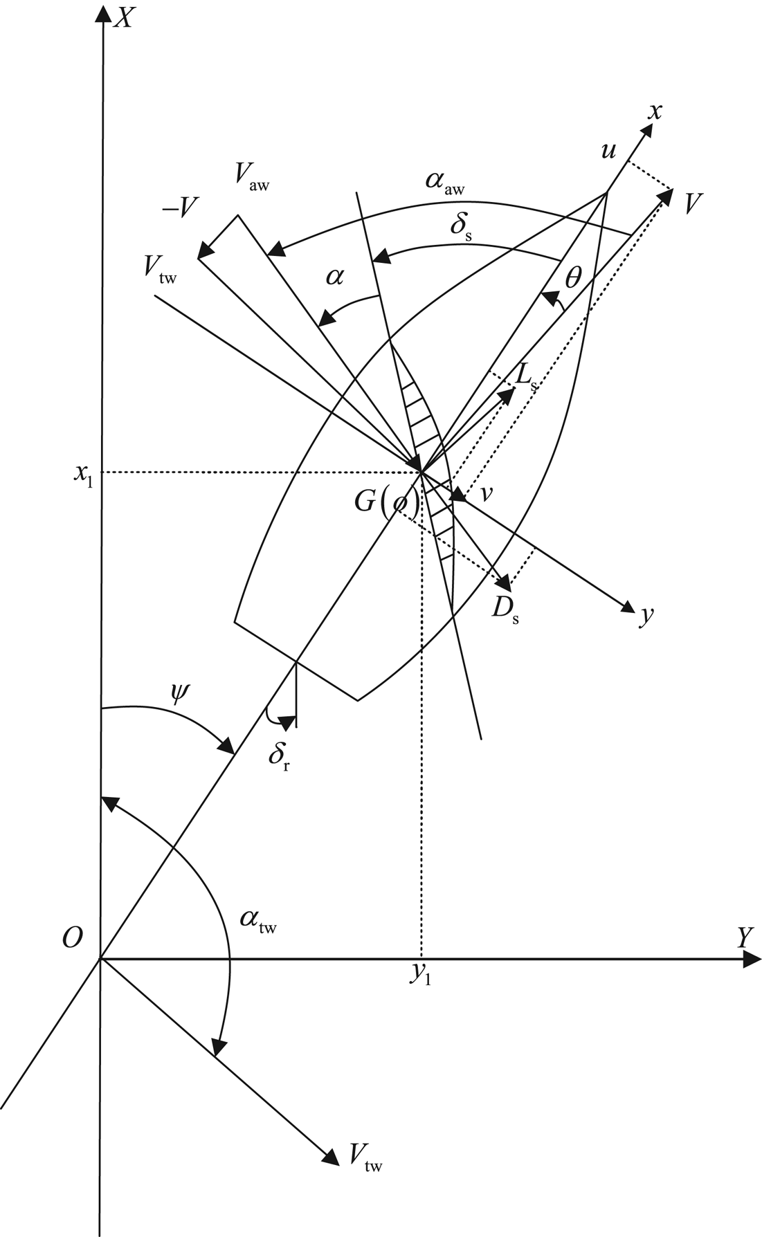
The earth-fixed reference frame $XOY$ and body-fixed reference frame $xoy$
 are shown in Figure 1. The coordinate origin $O$
 is the starting position of the unmanned sailboat, and the axes $OX$
 and $OY$
 point to the north and east, respectively; the coordinate origin $o$
 is the centre of gravity of the unmanned sailboat $G(o)$
 , the axis $ox$
 is directed from aft to fore and $oy$
 points to starboard. As shown in Figure 1, in the body-fixed reference frame, with the magnitude of the apparent wind ${V_{\rm aw}}$
 and direction ${\alpha_{\rm aw}}$
 , ${\delta _{\rm s}}$
 is the sail angle, $\alpha$
 represents the sail angle of attack and the leeway angle is $\theta$
 . These satisfy the formula ${\delta _{\rm s}}={\alpha_{\rm aw}}-\alpha -\theta$
 . The actual sailing speed is represented by $V$
 . It can be divided into the surge velocity $u$
 and the sway velocity $v$
 on different axes, and they satisfy the formula ${V^{2}} = {u^{2}} + {v^{2}}$
 . The ${L_{\rm s}}$
 and ${D_{\rm s}}$
 are the sail lift and drag forces, and the rudder angle is represented by ${\delta _{\rm r}}$
 . In the earth-fixed reference frame, ${V_{\rm tw}}$
 is the magnitude of the true wind and ${\alpha _{\rm tw}}$
 its direction. The position of the sailboat is represented by (${x_1}$
 , ${y_1}$
 ). The heading (yaw) angle of the unmanned sailboat is $\psi$
 , which represents the angle from the axis $ox$
 to $OX$
 .
Reference coordinate frames of the unmanned sailboat

Xiao and Jouffroy (Reference Xiao and Jouffroy2014) described the kinematics and kinetics equations of an unmanned sailboat. On this basis, we add disturbances such as waves or wind, so that a 4-DOF unmanned sailboat dynamic model is established as follows:

where $p$ , $\phi$
 and $r$
 denote the roll velocity, the roll angle and the yaw velocity, respectively; ${F_{x\cdot }}$
 , ${F_{y\cdot }}$
 , ${M_{x\cdot }}$
 , ${M_{z\cdot }}$
 are the forces and moments of different parts; and $s$
 , $r$
 , $k$
 and $h$
 represent the sail, rudder, keel and hull of the unmanned sailboat, respectively. Here, ${M_{\phi d}}(\dot \phi )$
 , ${M_{\psi d}}(\dot \psi )$
 and ${M_r}( \phi )$
 denote the heel-damping matrix, the yaw-damping matrix and the static-righting moment, respectively; ${I_{xx}}$
 and ${I_{zz}}$
 are the principle moment of inertia on $x$
 and $z$
 ; and ${X_{\dot u}}$
 , ${Y_{\dot v}}$
 , ${K_{\dot p}}$
 , ${N_{\dot r}}$
 represent the added mass coefficients. These formulae are detailed by Xiao and Jouffroy (Reference Xiao and Jouffroy2014). In (1), ${X_{\rm wave}}$
 , ${Y_{\rm wave}}$
 , ${K_{\rm wave}}$
 , ${N_{\rm wave}}$
 denote the force and moment produced by wave disturbances as follows:

where $m$ , $L$
 , $B$
 and ${A_a}$
 represent the mass, length, width and the sail area of the unmanned sailboat; $T$
 and $k$
 are the draft and the wavenumber; $\rho _{{\rm water}}$
 and $g$
 are the density of seawater and the acceleration of gravity; ${h_c}$
 , $\mu$
 and ${\omega _e}$
 denote the initial meta-centric height, the wave direction angle and the encounter frequency, respectively. Among them, $a = \rho _{{\rm water}}g( 1 - e^{ - kT} )/k^{2}$
 , $b = ( kL/2 )\cos \mu$
 , $c = ( {kB/2} )\sin \mu$
 , $\xi ( t ) = ( {h/2} )\cos ( \omega _e t )$
 , $\varepsilon ( t ) = ( {kh/2} )\sin ( {{\omega _e}t} )$
 , and $h$
 is the significant wave height.
2.2. Problem formulation
From the 4-DOF unmanned sailboat dynamic model (1), we can get the mathematical model of the sailing speed,

where

When studying the ESC optimisation scheme, if the input and output of the optimised object are known, we can approximate the optimised object to a general nonlinear system. So the model (2) can be written as

where $f$ and $h$
 both are smooth functions representing the system state and output equation, and $\boldsymbol {x} \in \boldsymbol{R^{n}}$
 , ${\delta _s} \in \boldsymbol{R}$
 and $u \in \boldsymbol{R}$
 denote the system state, input and output.
The sail angle control law is

where ${\alpha _0}$ and ${\delta _\alpha }$
 represent the sail angle of attack and optimal sail angle of attack, respectively. Inserting (4) into (3), we get

Some assumptions are as follows:
Assumption 1 There is the smooth function $l:\boldsymbol{R} \to \boldsymbol{R^{n}}$ , where $f(\boldsymbol {x},\alpha (\boldsymbol {x},{\delta _\alpha })) =\boldsymbol {0}$
 is true if and only if $\boldsymbol {x} = l( {{\delta _\alpha }} )$
 .
Assumption 2 For any ${\delta _\alpha } \in \boldsymbol{R}$ , the solution to system (5) $\boldsymbol {x} = l( {{\delta _\alpha }} )$
 is local exponentially stable.
Assumption 3 There is $\delta _\alpha ^{*} \in R$ such that

It guarantees that $u = h(l({\delta _\alpha }))$ can obtain the optimal speed at the optimal value $\delta _\alpha ^{*}$
 .
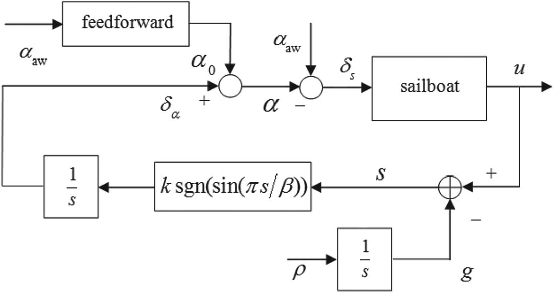
Assumption 4 In Figure 2, the adjustment rate of ${\delta _\alpha }$ determined by the ESC scheme is much slower than the system dynamic, and the system dynamic in (3) refers to the dynamic from ${\delta _\alpha }$
 to cost function $u(t)$
 . So to analyse the sliding mode more conveniently and simply, we ignore this dynamic at first, so the cost function $u(t) = h(\boldsymbol {x}(t))$
 can be approximated by

SMESC speed optimisation scheme

To sum up, the control objective is: under the above assumptions for the controlled object (5), ${\delta _\alpha }$ achieves the tracking of $\delta _\alpha ^{*}$
 in the process of optimisation, so that $u$
 reaches the maximum speed.
3. SMESC speed optimisation
In this paper, there are two parts in the control of an unmanned sailboat: a proportional-integral-derivative heading controller adjusts the rudder angle to track the desired heading; and the SMESC speed optimiser is designed to continuously change the sail angle to optimise the speed. Figure 2 shows the speed optimisation scheme.
3.1. Basic principles
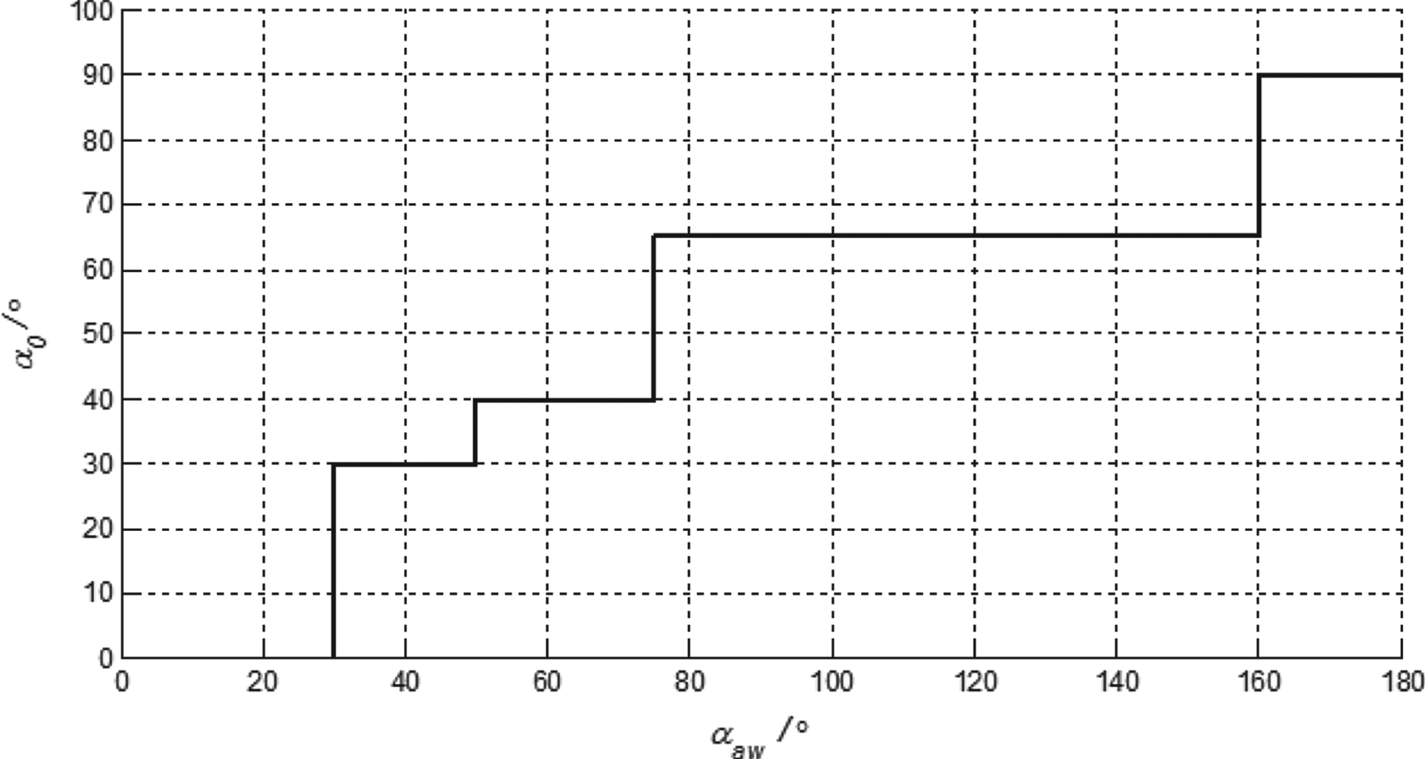
As shown in Figure 2, the speed optimisation scheme includes the feedforward part and the SMESC feedback part. The main function of this feedforward part is to avoid a large deviation between $u$ and the optimal value. The ${\alpha _0}$
 is first computed by a piecewise constant function. As shown in Figure 3, the piecewise constant function is obtained by a rough fitting based on the speed polar diagram information. The basic principle is to adjust $\alpha$
 based on different ${\alpha_{\rm aw}}$
 to produce the optimal ${F_{xs}}$
 and $u$
 .
Offline calculation of ${\alpha _0}$

For the feedback control, the basic idea is to devise the sliding mode control law ${\dot \delta _\alpha }=k\,{\rm sgn}(\sin (\pi s /\beta ))$ . During the sliding mode motion, no matter how the gradient of the function changes, $H({\delta _\alpha }(t)) - g(t)$
 will be kept as a constant, then $H({\delta _\alpha }(t))$
 will be forced at the same rate as $\rho$
 increases with $g(t)$
 . After the sliding mode extremum seeking feedback control, an ${\delta _\alpha }$
 is generated, and the actual $\alpha$
 is obtained by combining ${\alpha _0}$
 and ${\delta _\alpha }$
 . The actual control of an unmanned sailboat is ${\delta _s}$
 , not $\alpha$
 , where ${\delta _s}$
 is obtained from the formula ${\delta _s} = {\alpha_{\rm aw}} - \alpha$
 . The closed-loop control is formed by ${\delta _s}$
 acting on the controlled object. After feedback optimisation of the SMESC, $u$
 reaches the maximum speed value. However, due to the structural performance of SMESC, it has steady-state oscillation.
3.2. The analysis of sliding modes
The SMESC speed optimisation scheme is shown in Figure 2. The switching function $s(t)$ is defined as

where $g(t)$ is monotonically increasing and $\dot g(t) = \rho$
 is positive. Here, ${\dot \delta _\alpha }$
 satisfies

where $k$ , $\beta$
 are both positive, and the derivative of $s(t)$
 is

where $\Phi ({\delta _\alpha }) = ({d}/{{d{\delta _\alpha }}})H({\delta _\alpha })$ is the derivative of $H({\delta _\alpha })$
 to ${\delta _\alpha }$
 .
If a constant $c$ makes

true, the sliding mode occurs at $s(t) = c$ . The surge velocity $u(t)$
 increases with the increasing of $g(t)$
 , and the optimal ${\delta _\alpha }$
 moves towards the maximum $\delta _\alpha ^{*}$
 .
Next, a more rigorous and concise method is used to analyse the sliding modes compared with the analysis method of Pan et al. (Reference Pan, Qzguner and Acarman2003).
According to the sliding mode control law (8) and trigonometric function,

the corresponding switching function is defined as

It can be seen that the corresponding sliding modes are

where $n = 0, \pm 1, \pm 2\ldots$ .
First, analysing ${\Gamma _l}(t)$ and the derivative of ${\Gamma _l}(t)$
 gives

so

From (13), we can get the following conclusions:
(1) Under $\sin (\pi s(t)/\beta ) > 0$
 ($2n < s(t)/\beta < 2n + 1$) and $\Phi ({\delta _\alpha }) < {\rho }/{k}$, ${\Gamma _l}(t){\dot \Gamma _l}(t) < 0$ holds. Because of $\dot s(t) = \Phi ({\delta _\alpha }) k \,{\rm sgn}(\sin (\pi s(t)/\beta )) - \rho$, $\dot s(t) < 0$ is known, so $s(t)/\beta \to 2n$.
(2) Under $\sin (\pi s(t)/\beta ) < 0$
($2n + 1 < s(t)/\beta < 2n + 2$) and $\Phi ({\delta _\alpha }) < - {\rho }/{k}$, ${\Gamma _l}(t){\dot \Gamma _l}(t) < 0$ holds, $\dot s(t) > 0$ is known, so $s(t)/\beta \to 2n + 2$.


The same analysis of ${\Gamma _r}(t)$ gives


From (15), we can get the following conclusions:
(1) Under $\sin (\pi s(t)/\beta ) > 0$
($2n < s(t)/\beta < 2n + 1$) and $\Phi ({\delta _\alpha }) > {\rho }/{k}$, ${\Gamma _l}(t){\dot \Gamma _l}(t) < 0$ holds. Because of $\dot s(t) = \Phi ({\delta _\alpha }) k \,{\rm sgn}(\sin (\pi s(t)/\beta )) - \rho$, $\dot s(t) > 0$ is known, so $s(t)/\beta \to 2n + 1$.(2) Under $\sin (\pi s(t)/\beta ) < 0$
($2n + 1 < s(t)/\beta < 2n + 2$) and $\Phi ({\delta _\alpha }) > - {\rho }/{k}$, ${\Gamma _l}(t){\dot \Gamma _l}(t) < 0$ holds, $\dot s(t) < 0$ is known, so $s(t)/\beta \to 2n + 1$.


Unlike simple sliding mode control, which has only a single sliding mode, SMESC has a series of sliding modes that ensures a sliding mode is achieved regardless of the initial state of the system. Through the above analysis, a series of sliding modes of SMESC is drawn, as shown in Figure 4.
SMESC convergence process and sliding modes

Figure 4 shows the convergence process of the optimisation system, which consists of three phases:
A. The convergence phase – the system from the initial position converges to the nearest sliding mode.
B. The forced tracking phase – after reaching a sliding mode, the system is forced to track a preset reference signal and gradually converges to the neighbourhood of an extremum point, i.e. $\Phi ({\delta _\alpha }) \in ( -\rho /k,\rho /k)$
.C. The steady-state oscillation phase – it will maintain steady-state oscillation near the extremum point.

3.3. The stability analysis
First, the system is analysed from the initial position to the sliding mode and defines a $\delta$ neighbourhood of the extremum point $\delta _\alpha ^{*}$
 as

where ${\delta _l}$ and ${\delta _r}$
 are positive constants and satisfy


Based on the analysis of the sliding mode in the previous section, it can be seen that when $\Phi ({\delta _\alpha }) < - {\rho }/{k}$ , ${\Gamma _l}(t){\dot \Gamma _l}(t) < 0$
 is established, and the system converges to sliding mode ${\Gamma _l}(t) = 0$
 ; when $\Phi ({\delta _\alpha }) > {\rho }/{k}$
 , ${\Gamma _r}(t){\dot \Gamma _r}(t) < 0$
 is established, and the system converges to ${\Gamma _r}(t) = 0$
 . That is, for any initial state ${\delta _\alpha }(0)$
 of the system, as long as parameters $k$
 and $\rho$
 are selected to satisfy

then

will exist. The system converges to ${\Gamma _l}(t) = 0$ or ${\Gamma _r}(t) = 0$
 .
Next, the convergence of the optimisation system in sliding mode (phase II) will be analysed. The equivalent control theory is applied, the sliding mode control law is written

Let

the equivalent control input in the sliding modes $s(t) = n\beta$ can be obtained

It is known that $\delta _\alpha ^{*}$ is a maximum point, $({\delta _\alpha }- \delta _\alpha ^{*})\Phi ({\delta _\alpha }) < 0$
 when ${\delta _\alpha } \ne \delta _\alpha ^{*}$
 , and we get

In summary, the optimisation system gradually converges to the maximum value of the sliding mode.
Finally, we analyse the III phase. After the system converges to $| {\Phi ({\delta _\alpha })}| \le {\rho }/{k}$ , sliding modes disappear and there is

Supposing the optimisation system converges to $| {\Phi ({\delta _\alpha })}| \le {\rho }/{k}$ in mode $s(t)=(2n + 1)\beta$
 , there are


where ${\delta _\alpha }$ keeps going up, and two cases may occur.
Case 1: If the design of ${\rho }/{k}$ is small, the system will pass through $| {\Phi ({\delta _\alpha })} | \le {\rho }/{k}$
 to reach $| {\Phi ({\delta _\alpha })} | > {\rho }/{k}$
 before $s(t)$
 reduces to $2n\beta$
 . In this region, the sliding modes condition is established, the system converges to $s(t) = 2n\beta$
 and moves to $| {\Phi ({\delta _\alpha })} | \le {\rho }/{k}$
 after reaching the sliding mode, and we get


Now ${\delta _\alpha }$ continues to decrease until after the system converges to $s(t)=(2n - 1)\beta$
 , the system is going to move in the opposite direction, and ${\delta _\alpha }$
 keeps going up. The system is going to repeatedly move around the maximum point $\delta _\alpha ^{*}$
 , forming a large steady-state oscillation, as shown by the red trajectory in Figure 4.
Case 2: If the design of ${\rho }/{k}$ is large, the system is always in $| {\Phi ({\delta _\alpha })} | \le {\rho }/{k}$
 when $s(t)$
 reduces to $s(t) = 2n\beta$
 . Then (29) and (30) are established, and the motion direction of ${\delta _\alpha }$
 reverses. When (27) and (28) are established, the motion direction of ${\delta _\alpha }$
 reverses again. The system will repeatedly move around the maximum point $\delta _\alpha ^{*}$
 , forming a smaller steady-state oscillation, as shown by the pink trajectory in Figure 4. Therefore, the convergence of the SMESC speed optimisation system has been proved.
4. SMESC without steady-state oscillation speed optimisation
In Section 3, a speed optimisation scheme based on SMESC is proposed. Its performance depends on the pre-designed sliding mode. The performance of the algorithm will not be affected by the parameters uncertainty and external disturbances after the sliding mode occurs. That is to say, in the sliding mode, the speed optimisation system converges to the extremum of the cost function at a preset speed, regardless of changes in system parameters and cost function. However, from the stability analysis of the SMESC system, it is known that steady-state oscillation will be generated in the III phase, which is reached during its application in practical systems. In this section, steady-state oscillation will be eliminated by combining SMESC with ESC without steady-state oscillation.
4.1. Basic principles
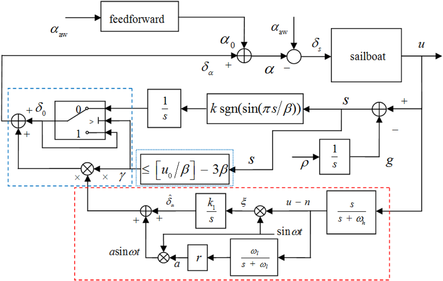
Based on the idea of switching between algorithms, by designing a switching law to combine SMESC with ESC without steady-state oscillation, the improved speed optimisation scheme by SMESC without steady-state oscillation is proposed and shown in Figure 5.
SMESC without steady-state oscillation speed optimisation

In Figure 5, the red dashed box is the ESC without steady-state oscillation, whose introduction and stability proof are detailed by Shen et al. (Reference Shen, Wang, Yu and Guo2019). The switching law consists of two parts: one is the blue dotted box part on the right side, which can detect the convergence state of SMESC. When a certain state satisfies the switching condition, the system switches from SMESC to ESC without steady-state oscillation; the other is the blue dashed box on the left, which is a value holder. When the switching condition is satisfied, the value holder starts to work, which ensures the stability of the switch. The key to complete this improved scheme is to design the switching law.
4.2. Design of the switching law
To make full use of the advantages of the convergence phase of SMESC, and to combine it with the steady-state phase of ESC without steady-state oscillation, the switch action should be designed at the end of the SMESC forced trace phase, i.e. phase II, and during the switching period, the ${\delta _\alpha }$ should not jump. First, the detection of the convergence phase of the SMESC will be stated in detail for the $s(t)$
 signal at the initial time

where ${s_0}$ , ${u_0}$
 and ${g_0}$
 are initial values. Here, ${g_0}$
 is zero, so

For any initial value ${u_0}$ , there are three possibilities where $s(t)$
 converges to sliding modes, i.e. $[u_0/\beta ]$
 and $[u_0/\beta ] \pm \beta$
 , and $[ \bullet ]$
 represents the rounding function. When this optimisation system converges to $| {\Phi ({\delta _\alpha })} | < {\rho }/{k}$
 , the sliding mode disappears and there is

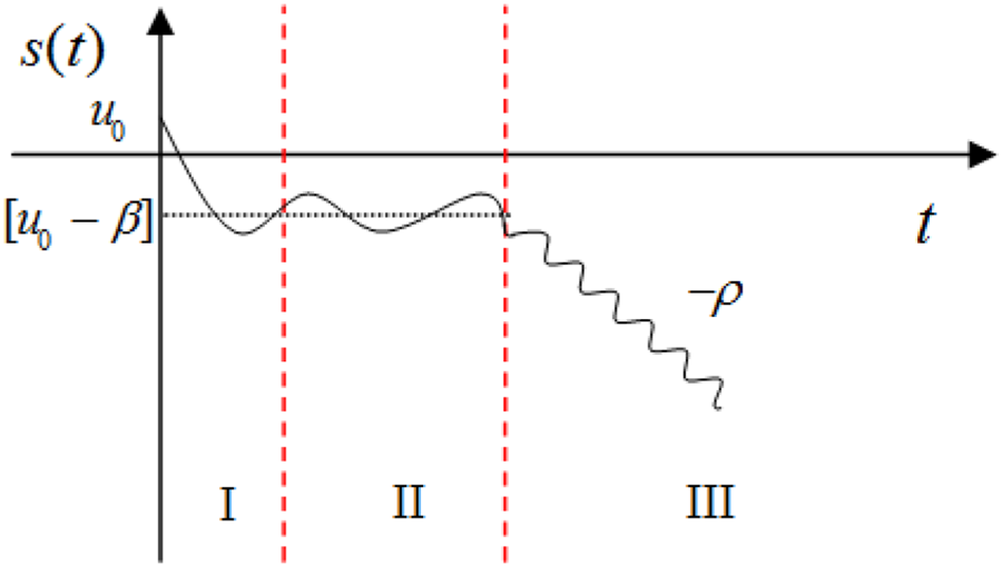
To sum up, the general trend of $s(t)$ is shown in Figure 6.
The trend of $s(t)$

In Figure 6, first the signal $s(t)$ converges to the nearest sliding mode. After the end of the forced tracking phase, the SMESC enters the III phase and $s(t)$
 changes significantly. So the signal $s(t)$
 is used to determine whether the optimisation system has reached the steady-state oscillation phase. In summary, the threshold of the switching law can be set to $[u_0/\beta ] - \beta$
 , but to avoid the false switching caused by the sliding chattering, it is preferable to set the next sliding mode ($[u_0/\beta ] - 3\beta$
 ) as a switch threshold, and obtain the conservative switching law

It can be known from (33) and (34) that only one switch is made in the optimisation process. The switching law includes two parts: the state judgment and value holder. When $s(t) > [u_0/\beta ] - 3\beta$ , $\gamma = 0$
 , and the SMESC is working; when $s(t) \le [u_0/\beta ] - 3\beta$
 , $\gamma = 1$
 , ESC without steady-state oscillation starts to work. When the switching condition is satisfied, the value holder starts to work, which is used to maintain the estimated input value ${\delta _0}$
 in SMESC. This is added to the optimisation system as the initial value of ESC without steady-state oscillation.
4.3. Stability analysis
Before carrying out the stability analysis of the entire optimisation system, the stability of the ESC without steady-state oscillation should be briefly introduced. The detailed stability proof has been analysed by Shen et al. (Reference Shen, Wang, Yu and Guo2019), and has led to the Theorem 1.
Theorem 1 System (5) under the Assumptions 1–3 for the ESC without steady-state oscillation speed optimisation system in Figure 4. There are constants ${\omega ^{*}}$ , ${\delta ^{*}}$
 and ${\varepsilon^{*}}$
 , together with a neighbourhood of $(x,{\hat \delta _\alpha },a,n) = (l(\delta _\alpha ^{*}),\delta _\alpha ^{*},0,h \circ l(\delta _\alpha ^{*}))$
 , such that $(x(t),{\hat \delta _\alpha }(t),a(t),n(t))$
 converges exponentially to $(l(\delta _\alpha ^{*}),\delta _\alpha ^{*},0,h \circ l(\delta _\alpha ^{*}))$
 for parameters $\omega \in (0,{\omega ^{*}})$
 , $\delta \in (0,{\delta ^{*}})$
 , $\varepsilon \in (0,{\varepsilon^{*}})$
 . That is, the surge velocity $u$
 converges exponentially to the optimal value $h \circ l(\delta _\alpha ^{*})$
 .
Based on the analysis of this entire optimisation scheme, Theorem 2 is obtained.
Theorem 2 System (5) and the cost function (6) under the Assumptions 1–4, for the SMESC without steady-state oscillation speed optimisation scheme in Figure 5. There are constants ${\omega ^{*}}$ , ${\delta ^{*}}$
 , ${\varepsilon^{*}}$
 and ${\beta^{*}}$
 , such that for parameters $\omega \in (0,{\omega^{*}})$
 , $\delta \in (0,{\delta ^{*}})$
 , $\varepsilon \in (0,{\varepsilon^{*}})$
 and $\beta \in (0,{\beta^{*}})$
 , the optimisation system converges to optimal $\delta _\alpha ^{*}$
 . That is to say, the surge velocity $u$
 of the unmanned sailboat converges to an optimum value $H(\delta _\alpha^{*})$
 .
Proof. It is known that there is only one switching action in the SMESC without steady-state oscillation speed optimisation process. If SMESC is convergent and the ${\delta _\alpha }$ is in the convergence domain of ESC without steady-state oscillation after switching, this entire speed optimisation system is convergent.
The stability of SMESC has been proved in Section 3.3. Due to the choice of parameters, there are two cases in the steady-state oscillation phase. Considering the critical state in the two cases, that is, the variation range of $\Phi ({\delta _\alpha })$ is only $[- \rho / k, \rho /k]$
 , this system goes into $| {\Phi ({\delta _\alpha })} | \le {\rho }/{k}$
 at ${t_0}$
 , and it gets to another boundary at ${t_1}$
 .
When $s(t)$ is $2n\beta < s(t) < (2n + 1)\beta$
 , there is


where $\Phi ({\delta _\alpha }) \in [- \rho /k ,\rho /k]$ , so $\dot s(t) \in [ - 2\rho ,0]$
 . Based on the Lagrange Mean Value Theorem, ${\bar s_1} \in ( - 2\rho ,0)$
 is the mean of $\dot s(t)$
 , so

is true.
When $s(t)$ is $(2n - 1)\beta < s(t) < 2n\beta$
 , there is


where $\Phi ({\delta _\alpha }) \in [- \rho /k,\rho /k]$ , $\dot s(t) \in [ - 2\rho ,0]$
 . There is ${\bar s_2} \in ( - 2\rho ,0)$
 such that

holds. In summary, the following conclusion is obtained.
Consider the SMESC optimisation system. For $\rho /k > 0$ , there is a positive ${\beta^{*}} = \min (\beta _1^{*},\beta _2^{*})$
 , such that for $\beta \in (0,{\beta^{*}})$
 , $\Phi ({\delta _\alpha })$
 satisfies $| {\Phi ({\delta _\alpha })} | \le {\rho }/{k}$
 . Further, make

where $\delta _\alpha^{*}$ is the maximum point. Where $\Phi ({\delta _\alpha }) = ({d}/{{d{\delta _\alpha }}})H({\delta _\alpha })$
 and $\dot \Phi ({\delta _\alpha }) < 0$
 , we get

Let

where ${\tilde \delta _{\alpha \textrm {max}}}$ is the maximum extremum estimation error of the SMESC optimisation system in $| {\Phi ({\delta _\alpha })} | \le {\rho }/{k}$
 . From (42), for any positive constant $\tilde \delta _\alpha^{*}$
 , there is $\rho /k$
 such that ${\tilde \delta _{\alpha \textrm {max}}} \le \tilde \delta _\alpha^{*}$
 , where $\tilde \delta _\alpha^{*}$
 is the extremum estimation error in the ESC without steady-state oscillation optimisation system. Further, for any positive $\tilde \delta _\alpha^{*}$
 , there is a ${\beta^{*}}$
 , such that for $\beta \in (0,{\beta^{*}})$
 , ${\tilde \delta _{\alpha \textrm {max}}} \le \tilde \delta _\alpha^{*}$
 is established. That is, the ${\delta _\alpha }$
 after switching is within the convergence domain of ESC without steady-state oscillation. Therefore, Theorem 4.2. is established, and the SMESC without steady-state oscillation speed optimisation system is convergent.
5. Simulation studies
In this section, the 12-m unmanned sailboat model of Xiao and Jouffroy (Reference Xiao and Jouffroy2014) was used as the research object for verification and simulation. The parameters are $m = 25{,}900$ kg, $L = 12$
 m, $B = 3{\cdot }21$
 m, ${I_{xx}}=133{,}690$
 kg$\cdot$
 m$^{2}$
 , ${I_{{\rm zz}}}=24{,}760$
 kg$\cdot$
 m$^{2}$
 , and the detailed parameters are shown by Xiao and Jouffroy (Reference Xiao and Jouffroy2014).
5.1. Simulations without disturbance
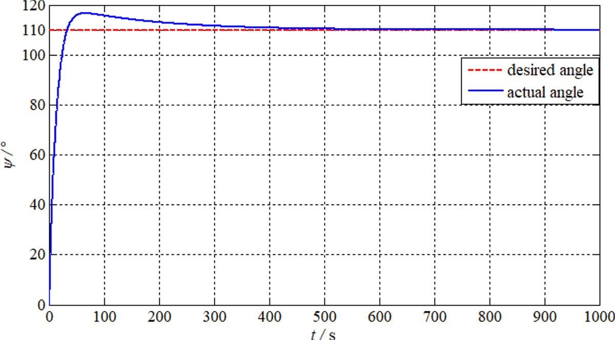
In the absence of disturbance, the initial heading and position are $0^{\circ }$ and $(0,0)$
 , the desired heading is $110^{\circ }$
 , initial $u$
 is 2 m/s, $V_{{\rm tw}}$
 is set as 5 m/s, and the wind blows from the north to the south. According to the Beaufort wind scale, the wind is level 3 the sea state is level 2. The parameters of the traditional SMESC scheme are chosen as $k = 0{\cdot }19$
 , $\beta = 19$
 , $\rho = 16$
 ; the parameters of the ESC without steady-state oscillation scheme are $r = 0{\cdot }08$
 , ${k_1} = 0{\cdot }12$
 , $\omega = 3$
 , ${\omega _l} = 0{\cdot }5$
 , ${\omega _h} = 1{\cdot }5$
 ; the parameters of the SMESC without steady-state oscillation scheme are $k = 0{\cdot }12$
 , $\beta = 19$
 , $\rho = 8{\cdot }3$
 , $r = 0{\cdot }08$
 , ${k_1} = 1$
 , $\omega = 3$
 , ${\omega _l} = 0{\cdot }1$
 , ${\omega _h} = 1$
 . The simulations are shown in Figures 7–11.
The yaw angle $\psi$ curve

The apparent wind angle $\alpha _{{\rm aw}}$ curve

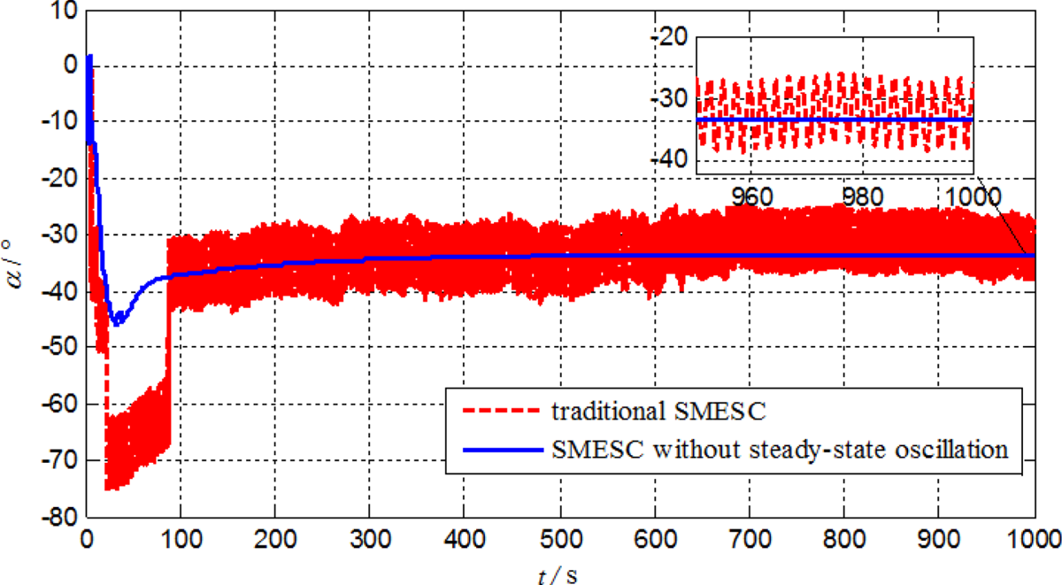
The actual $\alpha$ curve

The sail angle ${\delta_{\rm s}}$ curve

The optimisation of $u$ without disturbance

The curve of the unmanned sailboat actual heading is depicted in Figure 7. We can see that the sailboat can be maintained at the desired heading angle. Then, ${\alpha_{\rm aw}}$ , $\alpha$
 and ${\delta _s}$
 are shown in Figures 8–11, respectively, and satisfy ${\delta _s} = {\alpha_{\rm aw}} - \alpha$
 . It can be seen from the comparison of the two optimisation schemes that the system is gradually stable, and ${\delta _s}$
 and $\alpha$
 in the SMESC scheme contain large steady-state oscillation. Frequent changes of ${\delta _s}$
 will cause instability and shorten the service life of the equipment. However, the scheme we proposed can eliminate the steady-state oscillation.
During the ESC process, $\alpha$ and ${\delta _s}$
 are adjusted to the best position to maximise $u$
 . From Figure 11, we can see the maximum speed is approximately $3{\cdot }832$
 m/s as well as the tracking of the optimised speed of three different schemes and the model-based optimal value. The optimised speed of the three different schemes can track the theoretical maximum speed, and the SMESC without steady-state oscillation has the fastest convergence rate. From the locally enlarged image, the optimal speed of the SMESC without steady-state oscillation is superior to the other two schemes, and the steady-state oscillation existing in the SMESC scheme is also eliminated. This validates the effectiveness and better performance of our scheme.
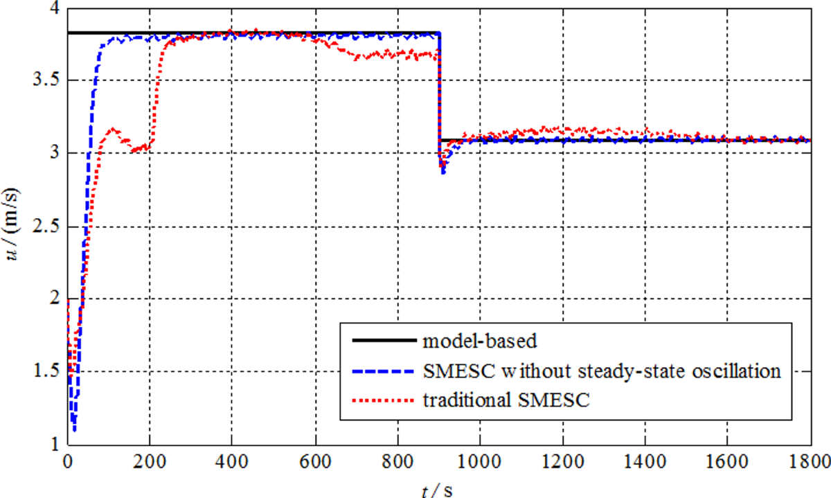
5.2. Simulations with disturbance
Next, simulations are carried out under the condition of disturbance to verify the strong robustness of this improved speed optimisation system, and the wind level and sea state are the same as those in subsection 5.1. The speed extremum point of the system is changed by changing the heading, so as to verify the adaptability of the SMESC without steady-state oscillation scheme for the changing extremum point system. The disturbance parameters are chosen as $T = 2{\cdot }15$ m, $k = 1$
 , $\mu = {2^ \circ }$
 , $h = 1$
 m, ${\omega _e} = 0{\cdot }3$
 Hz, ${\rho _{\rm water}} = 1025$
 kg/m$^{3}$
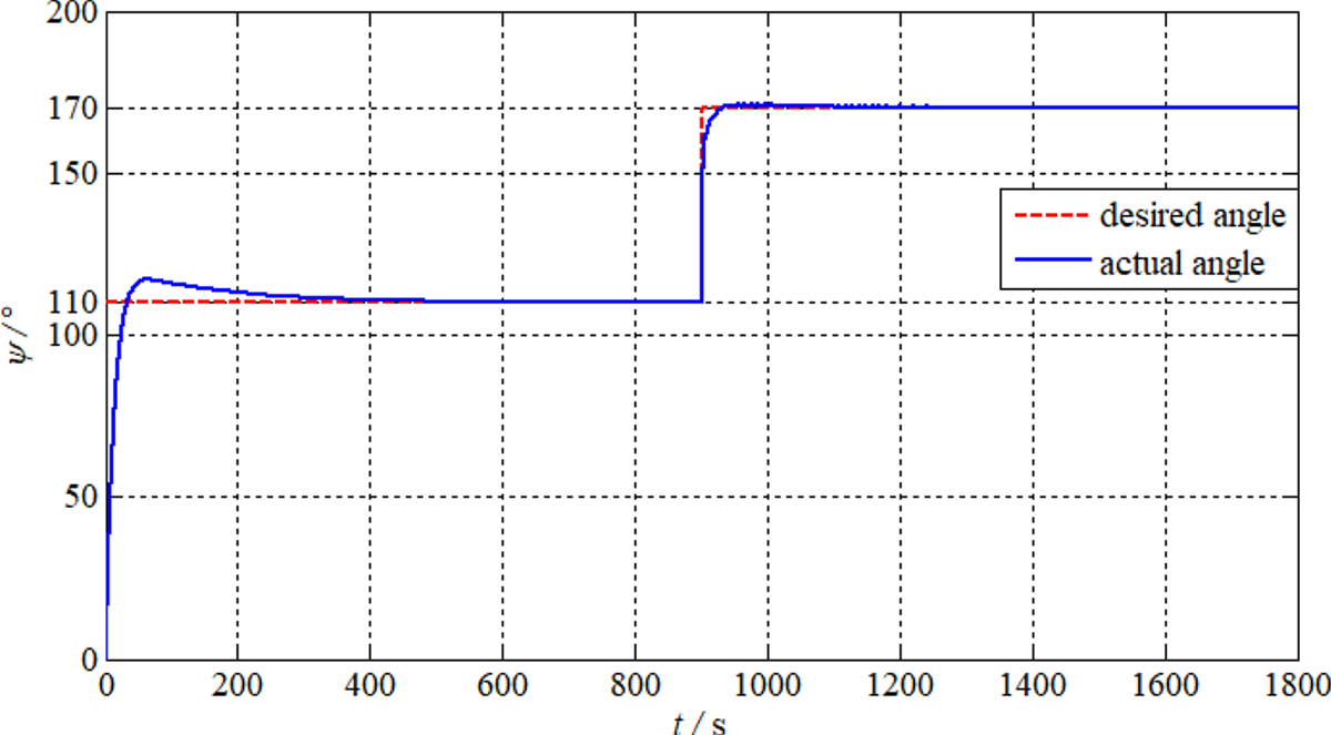
 . We set the desired heading to $11{0^{\circ } }$
 before $900$
 s, and the desired heading to $170^{\circ }$
 after $900$
 s. The simulations are shown in Figures 12 and 13.
The yaw angle $\psi$ curve

The optimisation of $u$ with disturbance

In Figure 12, the unmanned sailboat can track the desired heading well at two stages. In Figure 13, after the change of the speed extremum point, under the action of the SMESC without steady-state oscillation, the new speed extremum point can still be searched quickly and smoothly. However, the traditional SMESC optimisation scheme has a large deviation from the model-based optimal speed. Therefore, the SMESC without steady-state oscillation still has good adaptability to the changing extremum point system, the convergence rate and stability are better than traditional SMESC, and it is more robust for uncertain variables.
5.3. Speed polar diagram simulations
Finally, to verify the control accuracy of this improved optimisation scheme, the SMESC without steady-state oscillation optimisation speeds are compared with model-based maximum speeds under different headings, as shown in Figure 14.
The model-based maximum speeds and SMESC without steady-state oscillation results

The speed polar diagram shows the optimal steady-state speeds of unmanned sailboats in different headings, under a given wind condition. Under the sailboat dynamic model, the optimal speeds are obtained by simulation. First, a heading controller adjusts the rudder angle to track the desired heading, then continuously changes ${\delta _{\rm s}}$ to get the model-based maximum speeds. In Figure 14, a comparison between optimal speeds (red marks) based on SMESC without steady-state oscillation and the model-based maximum speeds (blue curve) is given. The results show that most values are matched in both cases. In other words, this novel speed optimisation scheme can ensure high control accuracy, and make the unmanned sailboat sail at the optimal speed state.
6. Conclusion
In this paper, a novel speed optimisation scheme based on SMESC without steady-state oscillation is presented, The traditional SMESC and ESC without steady-state oscillation are combined by designing a switching law. The optimal speed is sought and the steady-state oscillation is eliminated by using this scheme. This scheme includes feedforward and feedback: the initial sail angle of attack can be calculated offline in the feedforward part; the feedback control continuously optimises the sail angle to get the optimal speed. Also, the stability of the optimisation system is proved. Finally, based on a 12-m sailboat mathematical model, the simulation results show that the sailboat obtains the optimal speed. This improved scheme keeps a faster convergence rate and effectively eliminates steady-state oscillation. It has great adaptability to the changing extremum point system, and higher control accuracy and stronger robustness. However, there are still some shortcomings in this paper, such as no tests with real sailboats. The relationship between speed optimisation and path tracking control of unmanned sailboats is inseparable. Research on sailing strategies and path tracking control methods plays a significant role in achieving the safe navigation and energy-saving effects of unmanned sailboats. In the future, we will study the speed optimisation of the unmanned sailing strategy and path tracking control, and we will attempt to make tests with real boats.
Acknowledgments
This work was supported in part by National Natural Science Foundation of China under Grant 51809028 and Grant 51879027, in part by the China Postdoctoral Science Foundation under Grant 2020M670733, in part by the Doctoral Start-up Foundation of Liaoning Province under Grant 2019-BS-022, and in part by the Fundamental Research Funds for the Central Universities under Grant 3132019318.