I. INTRODUCTION
Reliable energy storage devices are needed to satisfy increasing demands in the fields of electronics, vehicles, and renewable energy generation systems, and lithium (Li) rechargeable batteries are promising candidates for these applications due to their high level of energy and power density.Reference Tarascon and Armand1 Intensive research efforts are currently focused on enhancing energy and power density of Li rechargeable batteries by exploring new electrode materials. Graphite is the most widely used anode for Li rechargeable batteries. However, its relatively low capacity, 372 mAh g−1, presents challenges for new applications in Li rechargeable batteries. Thus, much research has focused on developing next generation anode materials with higher levels of energy and power density than graphite-based anodes.Reference Zhang, Hu, Guo, Zheng, Zhong, Song and Wan2–Reference Kim, Seo, Kim, Kim and Kang9 Of particular interests among these studies have been those that have focused on conversion reaction compounds such as cobalt oxides, copper oxides, and nickel oxides due to their high theoretical capacity.Reference Liu and Zhang5, Reference Ryu, Kim, Kang and Park8–Reference Varghese, Reddy, Yanwu, Lit, Hoong, Rao, Chowdari, Wee, Lim and Sow16 Because simple metal oxides can react with more than one Li ion through conversion reaction, these compounds can exhibit high capacity.Reference Poizot, Laruelle, Grugeon, Dupont and Tarascon17
CoO and Co3O4, typical conversion reaction compounds, have been extensively studied due to their high theoretical capacities of ∼720 and 900 mAh g−1, respectively.Reference Ryu, Kim, Kang and Park8–Reference Li, Xu and Chen12, Reference Do and Weng18 However, toxicity and expensive production cost of cobalt-containing materials are major obstacles for commercialization.Reference Kim, Seo, Kim, Kim and Kang9, Reference Pasero, Reeves and West19, Reference Wang, Cui, Yang, Casalongue, Robinson, Liang, Cui and Dai20 Thus, attention has shifted toward lower cost transition metal-containing materials such as MnO, Mn2O3, and Mn3O4.Reference Pasero, Reeves and West19–Reference Fan and Whittingham24
Although Mn3O4 can exhibit high capacity through conversion reactions similar to Co3O4,Reference Pasero, Reeves and West19, Reference Wang, Cui, Yang, Casalongue, Robinson, Liang, Cui and Dai20, Reference Fang, Lu, Guo, Mao, Hu, Wang, Wang, Wu, Liu and Chen22 its intrinsically low electronic conductivity remains an obstacle for applications in Li rechargeable battery electrodes.Reference Pasero, Reeves and West19, Reference Wang, Cui, Yang, Casalongue, Robinson, Liang, Cui and Dai20, Reference Thackeray, David, Bruce and Goodenough23 Various approaches have been applied to address the problem of poor electronic conductivity: one approach involves the fabrication of nanostructured Mn3O4, such as nanofibers and nanorods,Reference Fang, Lu, Guo, Mao, Hu, Wang, Wang, Wu, Liu and Chen22, Reference Fan and Whittingham24 and another involves doping with other elements to facilitate the redox reactions.Reference Pasero, Reeves and West19
In this study, we report a Mn3O4/graphene hybrid anode fabricated using a simple in-situ reduction process. As well-dispersed graphene nanosheets (GNSs) provide nucleation sites for Mn3O4 under controlled synthetic conditions, small Mn3O4 (20–30 nm) particles can be directly grown on the conductive GNS network, resulting in good electrical contact between Mn3O4 particles and the conductive GNS. The electrochemical performance of the hybrid can be enhanced because GNS with excellent electronic conductivity makes a percolating network throughout the electrodes.
II. EXPERIMENTAL SECTION
To prepare the hybrid material, graphite oxide was first fabricated from graphite powder. Graphite oxide was synthesized by a modified Hummers method.Reference Hummers and Offenman25 Graphite (1 g), NaNO3 (1 g), and H2SO4 (46 mL) were stirred together in an ice bath for 30 min followed by slow addition of KMnO4 (5 g). The mixture was stirred for 2 h at 35 °C and deionized (DI) water (100 mL) and H2O2 (30%, 8 mL) were added. The solution was filtered and washed with HCl (10%, 150 mL) and DI water (100 mL).Reference Guo, Song and Chen26 To produce graphene oxide (GO), the resultant graphite oxide (0.1 g) was added to DI water (400 mL) and the solution was sonicated for 90 min. GO layers were exfoliated from graphite oxide using this procedure. The resultant solution was centrifuged (4000 rpm, 5 min) to remove residual graphite oxide. To fabricate the Mn3O4/graphene hybrid material, MnCl2·4H2O (400 mg) and KMnO4 (200 mg) were added to the GO solution with DI water (400 mL). In addition, NH4OH (3800 μl) and hydrazine (NH2NH2, 35 wt%, 250 μl) were added to reduce GO.Reference Kim, Kim, Park, Gwon, Seo, Kim and Kang27, Reference Gómez-Navarro, Weitz, Bittner, Scolari, Mews, Burghard and Kern28 The solution was stirred for 8 h at 80 °C, filtered, and dried at 120 °C for 2 h.
The product structure was characterized by x-ray diffraction [XRD, D/MAX-RC(12 kW)] with Cu Kα radiation (λ = 1.5418 Å) in the scan range of 20–80°. Mn3O4/graphene hybrid material was analyzed using a high-resolution dispersive Raman microscope (LabRAM HR UV/Vis/NIR) with Raman shifts from 100 to 2000 cm−1. Also, the morphology of the product was analyzed by scanning electron microscopy (SEM) and transmission electron microscopy (TEM).
Electrodes were prepared by mixing the Mn3O4/graphene hybrid material (90 wt%) with polyvinylidene fluoride (10 wt%) in N-methyl-2-pyrrolidone solvent for electrochemical characterization. The resultant slurry was uniformly pasted onto Cu foil. The electrodes were dried at 120 °C for 2 h and roll-pressed. The loading of active component (Mn3O4/graphene) in the electrode was 1.36 mg/cm2. Test cells were assembled into two-electrode cells with an Li metal counter electrode, a separator (Celgard 2400), and an electrolyte of lithium hexafluorophosphate (1 M) in a 1:1 mixture of ethylene carbonate and dimethyl carbonate (Techno Semichem, Seongnam, Republic of Korea) in a glove box. Electrochemical profiles were obtained in the voltage range from 0.001 to 3.0 V at various current densities from 100 to 1000 mA g−1 (∼0.1 C to 1 C) using a multichannel potentio-galvanostat (Maccor, Tulsa, OK). Impedance analysis was performed using 1255 HF frequency response analyzer (Solartron, Farnborough, UK) from 100 kHz to 0.1 mHz.
III. RESULTS AND DISCUSSION
Generally, the use of MnCl2·4H2O and KMnO4 produces MnO2 with Mn (IV).Reference Chen, Zhu, Wu, Han and Wang29 However, in this work, we introduced hydrazine which works as a strong reduction agent in the high pH levels. As a consequence, lower valent manganese oxide (Mn3O4) was fabricated.
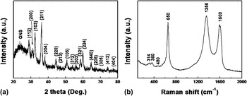
The phase purity of the Mn3O4/graphene hybrid material fabricated from the reduction process was analyzed by XRD. The major diffraction patterns matched well with those of Hausmannite Mn3O4 (JCPDS card no. 24-0734) with no impurity phases or other MnOx phases, as shown in Fig. 1(a).
X-ray diffraction (XRD) pattern and Raman spectrum of the Mn3O4/graphene hybrid.

The characteristic diffraction peak of GNS at around 25° confirmed the presence of graphene in the hybrid. In further analysis using Raman spectroscopy [Fig. 1(b)], broad peaks were observed at ∼1356 and 1600 cm−1, which were assigned to the D and G peaks of GNS, respectively.Reference Stankovich, Dikin, Piner, Kohlhaas, Kleinhammes, Jia, Wu, Nguyen and Ruoff30 The D peak corresponds to the mode of the k-point phonons of A1g symmetry, and the G peak is related to the E2g phonon of Csp2 atoms.Reference Tuinstra and Koenig31, Reference Ferrari and Robertson32 The Raman peaks at ∼314, 360, 480, and 650 cm−1 were attributable to the A1g, F2g(1), F2g(2), and Eg modes of Mn3O4, respectively.Reference Julien and Massot33, Reference Dubal, Dhawale, Salunkhe and Lokhande34
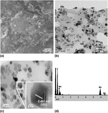
The morphology of the hybrid material was investigated by SEM and TEM. Small Mn3O4 particles were observed on the wrinkled GNS in the SEM image, as shown in Fig. 2(a). The particle size of Mn3O4 observed in TEM images was approximately 20–30 nm [Fig. 2(b)]. In SEM and TEM analysis, it was confirmed that the hybrid material is porous, which can decrease gravimetric fraction of the active material practically. However, the large surface area and porosity can contribute to the excellent rate capability of the hybrid material. The high-resolution TEM image indicated that they were highly crystalline with crystal lattice fringes of 0.491 nm, which was consistent with the (101) plane of Mn3O4 [Fig. 2(c)]. Energy dispersive spectroscopic analysis confirmed the presence of Mn, O, and C in the hybrid material, indicating that it consists of manganese oxides and GNS. The composition of the Mn3O4/graphene hybrid material was determined using an element analyzer (EA11110-0RISONS, CE Instruments, Wigan, UK). The weight content of carbon, primarily graphene, was ∼15 wt%.
Scanning electron microscopy and transmission electron microscopy images and energy dispersive spectroscopic (EDS) spectrum of the Mn3O4/graphene hybrid material. (a) and (b) show Mn3O4 particles uniformly dispersed on graphene nanosheets, and (c) confirm that the particle size of Mn3O4 was ∼20–30 nm. EDS analysis (d) confirmed the presence of Mn, O, and C in the hybrid material.

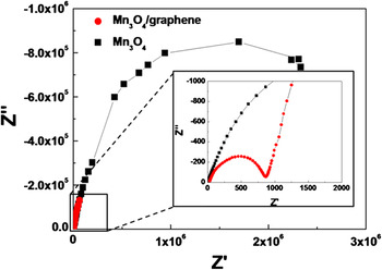
Electrochemical properties of the hybrid Mn3O4/graphene were investigated. First, impedance analysis was conducted on the Mn3O4/graphene hybrid material and compared with bare Mn3O4. The bare Mn3O4 electrode was prepared by simply mixing Mn3O4 with 15 wt% conductive carbon (Super P), equivalent to the amount of graphene in the Mn3O4/graphene hybrid. It should be noted that the conductive carbon (∼10 wt%) is typically further added even to the hybrid material in the preparation of electrodes to increase the electronic conductivity, especially for conversion reaction electrodes.Reference Qiang and Wang10, Reference Yang, Cui, Pang, Cao, Kolb, Feng, Maier and Mullen11, Reference Wang, Cui, Yang, Casalongue, Robinson, Liang, Cui and Dai20 However, the addition of carbon in the electrode lowers the total capacity. Thus, we did not add conductive carbon any further in preparing the electrode, in this work. The graphene introduced in the hybrid material functioned solely as a conductive matrix. Impedance analysis was performed in the range from 100 kHz to 0.1 mHz. Figure 3 shows that the conventionally prepared Mn3O4 electrode with Super P exhibited significantly higher impedance than that of the Mn3O4/graphene electrode. An equal amount (15 wt%) of carbon incorporated in the hybrid material would have dramatically lowered the impedance of the electrode.
Alternating current (AC) impedance analysis of the Mn3O4/graphene hybrid material and bare Mn3O4.

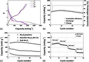
The charge storage capability of the Mn3O4/graphene hybrid was measured by galvanostatic charge/discharge cycling at a current density of 100 mA g−1 in a voltage range from 0.001 to 3.0 V. Typical profiles of the 1st, 2nd, 5th, and 10th cycles are shown in Fig. 4(a). The 1st discharge capacity of the hybrid material was 1789 mAh g−1, and the reversible charge capacity was ∼1100 mAh g−1 at a rate of 100 mA g−1. The profile shapes of the first discharge were notably different from those of subsequent cycles. The discharge profile did not change after the first cycle, implying that the reaction mechanism of the first discharge may differ from that of the other cycles. The different reaction processes during cycles will be discussed later. Similar profile shapes after the second cycle indicated that the reversible reaction occurred.
Galvanostatic analysis of the Mn3O4/graphene hybrid material. (a) Typical profiles of the Mn3O4/graphene hybrid material, (b) Cyclability of the hybrid material with a current density of 100 mA g−1 (∼0.1 C, 1 C = 940 mA g−1), (c) cycle properties of the hybrid material, bulk Mn3O4, and nanofiber Mn3O4 in Ref. 24, and (d) rate capability of the hybrid material.

The hybrid material retained ∼990 mAh g−1 after 30 cycles with approximately 96% of coulombic efficiency, as shown in Fig. 4(b). Because our strategy was to fabricate nanosized Mn3O4 by introducing the graphene in the fabrication process, bulk-sized Mn3O4 particles were used as control group in this study. Although the bulk Mn3O4 electrode delivered a capacity about 800 mAh g−1 at the first discharge, it decayed very rapidly with increasing cycles. In comparison, the Mn3O4/graphene hybrid material maintained a higher capacity throughout the cycles, as shown in Fig. 4(c). Also, in comparison to the previous report on nanofiber Mn3O4 (Ref. 24), the Mn3O4/graphene hybrid material maintained over 900 mAh g−1 after 30 cycles, while nanofiber Mn3O4 exhibited only below 500 mAh g−1 (53% of theoretical capacity) after 30 cycles. The excellent electrochemical performance of the hybrid material was more pronounced at elevated current rates. At a rate of 1000 mA g−1, the hybrid material retained a capacity of ∼400 mAh g−1, demonstrating the high power capability of the hybrid material. We stress that we did not add conductive carbon in preparing the electrode, except in the incorporated graphene itself, whereas normally 10 wt% additional carbon was added to the electrode. Moreover, the total weight of the hybrid material was considered in the calculation of capacity in this work. Since not only Mn3O4 but also graphene can contribute to the capacity of the hybrid material in this study, the hybrid material can exhibit exceptionally high capacity about 990 mAh g−1 even higher current rate compared to their work.
Furthermore, the electrochemical performance of the hybrid is exceptionally excellent compared to previous works, e.g., fabrication of nanostructures, such as nanofibers and nanorods, and doping with other elements to facilitate the redox reactions.Reference Pasero, Reeves and West19, Reference Yu, He, Sun, Tang, Li, Chen and Huang21–Reference Fan and Whittingham24 The reasons why the Mn3O4/graphene hybrid material can exhibit excellent electrochemical performance result from its Unique nanostructure. (i) Because individual Mn3O4 nanoparticles were directly grown on GNSs, good electrical contact between Mn3O4 particles and GNSs was achieved. The GNSs with the percolating network throughout the electrodes enhanced electron transfer during the charge/discharge process. (ii) The volumetric change from the de/lithiation of Mn3O4 is effectively accommodated by the GNS network as well as the nanosize of Mn3O4 crystallite itself. (iii) Not only Mn3O4 but also graphene can contribute to the electrochemical reactions of the hybrid materials.
Recently, Fe3O4 and carbon nanotube composite was reported with the similar strategy.Reference Ban, Wu, Gillaspie, Chen, Yan, Blackburn and Dillon35 They used the carbon nanotube as conductive and buffer matrix. In our strategy, flexible two-dimensional (2D) nanosheet, which is graphene, was used as conductive and buffer matrix. We think that the flexible 2D sheet can reduce the detrimental effect of the large volume change of metal oxide associated with de/lithiation more effectively than one-dimensional (1D) carbon nanotube matrix. This is because metal oxide particles are placed between the 2D sheets, thus, the flexible sheets will more effectively buffer the volume change of the particles ensuring the electrical contact. Moreover, the 2D sheets can form conductive network readily due to the line contact between sheets compared to the electrical point contact between 1D wires.
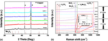
The electrochemical profile during the first cycle differed from those of subsequent cycles, indicating that an irreversible structural change occurred, as previously mentioned. To clarify this observation, the charge/discharge mechanism of the Mn3O4/graphene electrode was investigated by ex-situ structural analysis as a function of the charge state. The ex-situ XRD and Raman analysis on Mn3O4/graphene hybrid material, which elucidates the electrode behavior during the battery cycling, were carried out in this work. This information is critical in understanding and improving Mn3O4-based electrode in the future. First, ex-situ XRD measurements were acquired, as shown in Fig. 5 (a). As the lithiation of Mn3O4 proceeded, the characteristic peaks of Mn3O4 broadened and finally disappeared. The peaks were not recovered upon charging to 3.0 V, which is typical for conversion reactions involving the formation of nanoscale domains of the Li2O and Mn. However, we could not determine whether Mn3O4 was recovered due to the broad nature of peaks. Thus, further structural analysis was performed by ex-situ Raman spectroscopy at different charging states [Fig. 5(b)]. At 1.0 V in the first discharge, the Raman peak at ∼650 cm−1 shifted to 663 cm−1, indicating some degree of solid solution formation of LiyMn3O4 (1 ≤ y).Reference Fang, Lu, Guo, Mao, Hu, Wang, Wang, Wu, Liu and Chen22, Reference Thackeray, David, Bruce and Goodenough23 Upon further discharge, we observed that Li2CO3 began to form. Li2CO3 is thought to have formed from Li2O when the electrode was exposed to air and reacted with CO2 and moisture.Reference Tamura, Imanaka, Kamikawa and Adachim36 Further charging, the Raman peaks of Li2CO3 were reduced and a new Raman peak indexed as MnOx (x ∼ 2) evolved, indicating that Li2O disappeared and new MnOx formed through the reaction.Reference Huang, Pan and Huang37 The peaks from Mn3O4 did not reappear, implying that after the first cycle the electrode transforms into MnOx in subsequent cycles. It should be noted that oxygen-rich MnOx (x ∼ 2) were formed compared to the initial Mn3O4. It is probably due to the residual oxygen present as defects in the graphene that participates in the electrochemical reaction.Reference Kim, Kim, Hong, Lim, Kim, Yoo and Kang38 From the results, we conclude that Mn3O4 reacts with Li through a conversion reaction as follows:


Ex-situ structural analysis of the Mn3O4/graphene hybrid material at various voltages. (a) Ex-situ XRD analysis of the hybrid material at various voltages in the first cycle. (b) Ex-situ Raman analysis of the hybrid material at various voltages in the first and second cycles.

The reactions shown in Eqs. (1) and (2) occur only at the first discharge, and the reaction shown in Eq. (3) occurs reversibly for cycles. The theoretical capacity according to the suggested reaction is about 940 mAh g−1. However, both Mn3O4 and graphene can contribute to the capacity of the hybrid, therefore, the capacity (∼990 mAh g−1) of the hybrid can exceed the theoretical capacity of Mn3O4.
IV. SUMMARY
We demonstrated a simple and facile fabrication route for the Mn3O4/graphene hybrid material. Small Mn3O4 particles were uniformly dispersed on the GNSs and the resultant Mn3O4/graphene hybrid material exhibited an excellent electrochemical performance. The hybrid material retained a high capacity of ∼990 mAh g−1 after 30 cycles and maintained a high capacity of ∼400 mAh g−1 at an elevated current rate of as high as 1000 mA g−1. The promising electrochemical performance was achieved through the unique nanostructure of the hybrid material. This simple and easy hybrid-assembly process can be further used to fabricate various functional hybrid materials.
ACKNOWLEDGMENTS
This work was supported by a grant from the Fundamental R&D Program for Technology of World Premier Materials funded by the Ministry of Knowledge Economy, Republic of Korea and the National Research Foundation of Korea Grant funded by the Korean Government (MEST) (NRF-2009-0094219). This work was also supported by Energy Efficiency and Resources R&D program (20112020100070) under the Ministry of Knowledge Economy, Republic of Korea and by Human Resources Development of the Korea Institute of Energy Technology Evaluation and Planning (KETEP) grant funded by the Korea government Ministry of Knowledge Economy (20114010203120), and the project of Global PhD. Fellowship which National Research Foundation of Korea conducts from 2011.