





1. Introduction
Antarctica and Greenland hold the largest polar ice sheets on Earth, covering ∼11% of the entire global surface area (Singh and others, Reference Singh, Singh and Haritashya2011). Polar ice sheets, ranging in thickness from several metres to several kilometres, impede the sampling of subglacial bedrock, which provides direct evidence of palaeoclimate, geological tectonics and ice-sheet dynamics (Fountain and others, Reference Fountain, Usselman, Wooden and Langway1981; Schaefer and others, Reference Schaefer2016; Christ and others, Reference Christ2023; Bierman and others, Reference Bierman2024). Additionally, bedrock samples enable cosmogenic nuclide exposure dating, offering insights into the reversibility of ice-sheet retreat throughout geological history (Spector and others, Reference Spector2018; Briner and others, Reference Briner2022; Balco and others, Reference Balco2023; Johnson and others, Reference Johnson2025).
Subglacial bedrock samples are scarce, prompting the geological community to seek longer bedrock samples from deeper ice sheets. Since the first subglacial bedrock core was drilled in 1956 near Mirny Station, Antarctica, numerous cores have been extracted across polar regions to obtain subglacial bedrock samples (Talalay, Reference Talalay2013). In the last century, two samples of subglacial bedrock were retrieved at Camp Century and Summit Stations in Greenland (Ueda and Garfield, Reference Ueda and Garfield1968; Gow and Meese, Reference Gow and Meese1996). Recently, another subglacial bedrock was drilled beneath the 509 m thick ice sheet at Prudhoe Dome, North Greenland (Witze, Reference Witze2024). More than ten subglacial bedrock locations have been sampled in Antarctica, primarily in West Antarctica and the Transantarctic Mountains (Talalay, Reference Talalay2013; Braddock and others, Reference Braddock2024). Additionally, Chinese researchers have drilled two bedrock samples near the coast of Princess Elizabeth Land, East Antarctica (Talalay and others, Reference Talalay2021a, Reference Talalay2025). Currently, the deepest hole drilled for subglacial bedrock sampling reaches 681 m, and the longest subglacial core is 8 m (Goodge and others, Reference Goodge, Severinghaus, Johnson, Tosi and Bay2021; Kuhl and others, Reference Kuhl, Gibson, Johnson, Boeckmann, Moravec and Slawny2021).
Cable-suspended electromechanical drills (CSEDs) are extensively used for ice core drilling in polar regions. With minor modifications, they can also perform subglacial bedrock drilling, exemplified by the Polar Ice Coring Office-5.2″ and the Ice and Bedrock Electromechanical Drill (IBED) (Kelley and others, Reference Kelley, Stanford, Koci, Wumkes and Zagorodnov1994; Talalay and others, Reference Talalay2021a; Talalay and others, Reference Talalay2021b). Nonetheless, CSEDs are limited to extracting short bedrock samples due to the difficulty of supplying sufficient torque and downforce for subglacial bedrock coring. For instance, the initial bedrock core drilled by IBED was only 0.06 m, and a subsequent trial extended this to 0.48 m (Talalay and others, Reference Talalay2021a; Leitchenkov and others, Reference Leitchenkov2024a, Reference Leitchenkov2024b). Conventional rotary drill rigs (CRDRs) and coiled tubing drill rigs (CTDRs) can also be adapted for subglacial bedrock sampling through modifications for low-temperature environments (Clow and Koci, Reference Clow and Koci2002; Talalay, Reference Talalay2023). Presently, three CRDR types have been developed for subglacial bedrock coring in polar regions: the Winkie drill, the agile sub-ice geological drill and the rapid access ice drill (Goodge and Severinghaus, Reference Goodge and Severinghaus2016; Boeckmann and others, Reference Boeckmann2021; Kuhl and others, Reference Kuhl, Gibson, Johnson, Boeckmann, Moravec and Slawny2021). These CRDRs achieve theoretical drilling depths between 100 and 3000 m, allowing the extraction of longer rock cores. In contrast, CTDRs for subglacial bedrock coring remain conceptual and have yet to be practically implemented. In summary, only a few drills can sample bedrock beneath polar ice sheets.
Considering current technological capabilities, the modified CRDR remains the sole method for obtaining long rock cores beneath ice sheets. Presently, the USA and UK are the only countries equipped with CRDRs adapted for polar regions. However, all three aforementioned CRDRs are limited to drilling with drilling fluid, resulting in the possibility of hydraulic fracturing of the ice borehole due to pressure pulses from the drilling fluid (Goodge and others, Reference Goodge, Severinghaus, Johnson, Tosi and Bay2021; Kuhl and others, Reference Kuhl, Gibson, Johnson, Boeckmann, Moravec and Slawny2021). Such hydraulic fracturing can lead to drilling fluid loss, sometimes even necessitating borehole abandonment. Several studies have explored ice hydraulic fracture, and several methods have been proposed to prevent it in ice boreholes when using drilling fluid (Chen and others, Reference Chen2019; Zhang and others, Reference Zhang, Pan, Zhai, Zhang and Chen2018; Goodge and others, Reference Goodge, Severinghaus, Johnson, Tosi and Bay2021; Kuhl and others, Reference Kuhl, Gibson, Johnson, Boeckmann, Moravec and Slawny2021). Compressed air has been proven to be effective for ice drilling in polar regions and can prevent hydraulic fracturing due to the dampening nature of the compressible fluid (Cao and others, Reference Cao, Liu, Chen, Chen and Qi2018, Reference Cao, Cao, Cao, Liu and Chen2019; Gibson and others, Reference Gibson2021). However, it is not feasible in deep boreholes due to ice creep under high pressure. According to Wang and others (Reference Wang2017), the maximum air drilling depth should be restricted to 540 m at −20°C and 418 m at −10°C.
To address these issues, we propose a multi-process drilling system (MPDS) capable of drilling using compressed air and drilling fluid. Air drilling will be used from surface until the high hydrostatic pressure causes ice creep, leading to borehole shrinkage that ultimately restricts the movement of downhole tools. Subsequently, the drilling fluid must be used for drilling. To protect the borehole walls from hydraulic fracturing, a double-wall drill rod with reverse circulation was proposed to be utilised during ice drilling. When extracting a subglacial bedrock core, the MPDS employs wireline coring drilling with normal circulation (WCDNC), with the outer tube of the double-wall drill rod acting as casing to safeguard the ice borehole wall. Designed modularly, the MPDS allows for easy transportation and assembly on Antarctic ice sheets. This study presents the general concept, engineering design and preliminary testing results of the MPDS.
2. General concept
2.1. Technical requirements
As outlined in Table 1, the MPDS is required to drill boreholes to a minimum depth of 1000 m. There is no requirement to collect ice cores. The primary requirement for the MPDS is to obtain a bedrock core sample longer than 10 m with a diameter exceeding 35 mm. As discussed in Section 1, the MPDS can utilise three drilling methods: air reverse drilling, liquid reverse drilling and WCDNC. In air reverse drilling, ambient air is compressed, becoming hot and wet. To prevent compressed air from melting ice in the borehole and to avoid water vapour refreezing on the drill pipe or borehole wall at low temperatures, the compressed air was expected to be cooled below −5°C and dried to a dew point below −40°C. The drilling fluid should remain functional at temperatures above −55°C. Additionally, the drilling fluid was hoped to be cooled to below −2°C before being pumped into the borehole. The Chinese National Antarctic Research Expedition typically employs helicopters to transport cargo from icebreakers to Antarctic ice sheets. Currently, helicopters can lift only cargo weighing <5 tonnes; therefore, the MPDS must be modularly designed, with each module required to weigh <4 tonnes.
Technical requirements of the MPDS.

Table 1 Long description
Two columns list aspects and their requirements for drilling and sampling. Borehole depth is specified as greater than 1000 meters. Rock core length is at least 10 meters, and rock core diameter is at least 35 millimeters. Ice core is listed as without ice core. Drilling method includes air reverse drilling, liquid reverse drilling, and WCDNC. Compressed air is cooled to less than minus 5 degrees Celsius at the surface, with a dew point less than minus 40 degrees Celsius. Drilling fluid is specified to work at temperatures above minus 55 degrees Celsius and to be cooled to less than minus 2 degrees Celsius at the surface. Structure and weight are modularized, with each module less than 4 tonnes.
2.2. Conceptual model
As illustrated in Fig. 1, the MPDS is made of five subsystems: drill rig, drill-rod module, air system, drilling fluid circulation system and generator. Each module is integrated into a 20 foot container and transported by sledge across the Antarctic ice sheet. The drill rig serves as the primary equipment of the MPDS and is fully hydraulically driven. Most drilling operations, such as casing cementing and drill-rod connections, are performed within the drill rig container. The drill-rod module houses all drill rods and downhole tools and is positioned adjacent to the drill rig to facilitate downhole tool transport to the drill rig container. The air system primarily generates compressed air to remove ice chips from the borehole during shallow ice drilling. Compressed air is both dried and cooled within the air system. For deep ice and subglacial bedrock drilling, a drilling fluid circulation system is employed to prepare the drilling fluid, pump it into the borehole and separate cuttings from the returned liquid at the surface. If the drilling fluid’s temperature exceeds −2°C, it is cooled accordingly. All the drilling fluid is stored in a tank in the Antarctic field. A generator supplies electrical power to other subsystems. In the field, a fuel tank is used to provide fuel to the generator.
Schematic diagram of the MPDS.

2.3. Drilling process
Drilling a 1000 m borehole to obtain subglacial bedrock samples typically involves six steps (Fig. 2).
Drilling steps for subglacial bedrock coring.

Figure 2 Long description
Six steps involved in subglacial bedrock coring are illustrated. Step 1 shows air reverse drilling in firn, with a double-wall drill rod and a snow or firn drill bit reaching 10 meters into the snow or firn layer. Step 2 involves casing cemented in ice, with the casing extending through the snow or firn into the ice. Step 3 depicts air reverse drilling in ice, using an ice drill bit and air to penetrate deeper into the ice. Step 4 shows liquid reverse drilling in ice, with drilling liquid used to assist the ice drill bit. Step 5 involves lowering the outer tube of the double-wall drill rod as casing, with the outer tube extending into the ice. Step 6 illustrates wireline coring drilling in a subglacial lake, using a wireline and a drill rod for wireline coring, with a rock coring bit reaching 10 meters into the bedrock. Labels are included for snow or firn, ice, debris-rich ice and bedrock, with visual representations of the drill rods, bits and casing at each step.
In Step 1, a double-wall drill rod and a specially designed snow/firn drill bit are used to drill through snow and firn with air reverse circulation, ensuring the borehole extends at least 10 m into non-permeable ice with a density exceeding 830 kg m−3 (Cuffey and Paterson, Reference Cuffey and Paterson2010). Subsequently, the downhole tools are removed from the borehole. In this step, ice coring tools should be used at depths that are first identified by geophysical methods, such as radar and seismic surveys, to verify the ice density.
In Step 2, the casing is lowered to the bottom of the borehole, and melting water is pumped in to fill the lower section. The melting water then freezes, sealing the gap between the casing and the borehole wall. In this step, melting water occupies only the lower section of the borehole with solid ice; otherwise, the melting water may leak into the surrounding snow or firn.
In Step 3, an ice drill bit is utilised to penetrate the frozen water in the lower portion of the borehole and the underlying ice through air reverse circulation. Notably, the ice drill bit has a smaller diameter compared to the snow/firn drill bit. Ice drilling with air reverse circulation continues until the high hydrostatic pressure causes ice creep, leading to borehole shrinkage that ultimately restricts the movement of downhole tools (Talalay and Hooke, Reference Talalay and LeB. Hooke2007; Talalay and others, Reference Talalay2014).
In Step 4, drilling fluid is employed to balance the pressure on the borehole wall using reverse circulation. In this situation, pressure pulses from the pump and pipeline are confined within the double-wall drill rod, and the borehole wall pressure is solely hydrostatic pressure. Consequently, the borehole wall remains relatively secure, reducing the likelihood of hydraulic fracturing. However, the borehole near the drill bit face may still experience pressure spikes and potential hydrofracturing. It is worth noting that if reverse circulation is not properly established, the benefit of reduced pressure on the ice borehole wall will be lost. Liquid reverse drilling proceeds until bedrock is encountered. Subsequently, all downhole tools are retrieved to the surface, and the inner tube is extracted from the double-wall drill rod.
In Step 5, the outer tube of the double-wall drill rod is lowered to the borehole, serving as casing to protect the borehole wall from hydraulic fracturing during subsequent bedrock drilling.
In Step 6, the conventional WCDNC method is employed to obtain a bedrock sample. This step utilises normal drilling fluid circulation, with drilling fluid pumped from the central passage of the wireline coring drill rod, then returning to the surface through the gap between the outer tube of the double-wall drill rod and the wireline coring drill rod.
3. Borehole structure and hydraulic consideration
3.1. Borehole structure
Figure 3 illustrates the typical borehole structure of the MPDS during subglacial bedrock drilling. Generally, the borehole contains three spuds. The first spud has a diameter of 178 mm and is cemented with casing. Here, casing cementing refers to the sealing of the gap between the casing and the borehole wall by freezing water. It extends through the entire snow/firn layer down to solid ice, typically reaching depths of <120 m in Antarctica. The second spud, with a diameter of 110 mm, extends to the bedrock, targeting depths beyond 1000 m. In this spud, the outer tube of the double-wall drill rod functions as casing to safeguard the ice borehole wall. The third spud, used for bedrock sampling, has an expected length exceeding 10 m and a diameter of 67 mm.
Borehole structure.

3.2. Hydraulic consideration
The MPDS employs both compressed air and drilling fluid for subglacial bedrock coring. This section calculates the required flow rates and pressure of compressed air and drilling fluid during circulation based on the described borehole structure.
3.2.1. Air consumption
Air consumption during the drilling of snow/firn and ice is determined using the methods outlined by Cao and others (Reference Cao, Liu, Chen, Chen and Qi2018, Reference Cao, Cao, Cao, Liu and Chen2019). In our calculations, the penetration rate is set at 100 m h−1, and the ambient temperature at the drilling site is −30°C. The ice chip size is assumed to be 5 mm, representing the largest chips typically produced by cutters in ice core drilling (Hong and others, Reference Hong, Fan, Liu, Liu, Liu and Talalay2015). The drag coefficient between ice chips and compressed air is presumed as 0.8, with the ice chip concentration in the flow channel fixed at 0.04. To ensure adequate flow rate and pressure, safety factors of 1.5 for flow rate and 1.2 for pressure are applied. We assume drilling depths <120 m in snow/firn and <800 m in ice using compressed air.
Figure 4 illustrates the required airflow rate and pressure for snow/firn and ice drilling. Notably, the required air pressure increases linearly with drilling depth, while the airflow rate initially rises slowly and then accelerates with depth. Generally, the required airflow rate and pressure remain below 6 Nm3 min−1 (1 Nm3 denoting 1 m3 of air at normal conditions of 0°C and 101.325 kPa) and 0.9 MPa in snow/firn drilling, respectively. Air drilling in ice necessitates an airflow rate below 5 Nm3 min−1 and an air pressure beneath 1.7 MPa. Although ice drilling with air has much deeper borehole depth than snow/firn drilling, it demands an even lower airflow rate due to the narrower diameter of the boreholes.
Required airflow rate and pressure in (a) snow/firn drilling and (b) ice drilling.

Figure 4 Long description
A line graph with two lines and a legend listing, Required pressure of air and Required flow rate of air. The horizontal axis label at the top reads, Required pressure of air (MPa), with tick labels 0.0, 0.3, 0.6, 0.9, 1.2, 1.5, 1.8. The horizontal axis label at the bottom reads, Required flow rate of air (Nm3 min minus 1), with tick labels 1, 2, 3, 4, 5, 6. The vertical axis label reads, Drilling depth (m), with tick labels 0, 20, 40, 60, 80, 100, 120. The Required pressure of air line has plotted points at drilling depth 0 with pressure 0.0, depth 20 with pressure 0.1, depth 40 with pressure 0.2, depth 60 with pressure 0.3, depth 80 with pressure 0.4, depth 100 with pressure 0.5 and depth 120 with pressure 0.6. The Required flow rate of air line has plotted points at drilling depth 0 with flow rate 1.5, depth 20 with flow rate 2.5, depth 40 with flow rate 3.2, depth 60 with flow rate 4.0, depth 80 with flow rate 4.7, depth 100 with flow rate 5.3 and depth 120 with flow rate 6.0. The image B showing a line graph with two lines and a legend listing, Required pressure of air and Required flow rate of air. The horizontal axis label at the top reads, Required pressure of air (MPa), with tick labels 0.0, 0.3, 0.6, 0.9, 1.2, 1.5, 1.8. The horizontal axis label at the bottom reads, Required flow rate of air (Nm3 min minus 1), with tick labels 1, 2, 3, 4, 5, 6, 7. The vertical axis label reads, Drilling depth (m), with tick labels 0, 100, 200, 300, 400, 500, 600, 700, 800. The Required pressure of air line has plotted points at drilling depth 0 with pressure 0.0, depth 100 with pressure 0.2, depth 200 with pressure 0.4, depth 300 with pressure 0.6, depth 400 with pressure 0.8, depth 500 with pressure 1.0, depth 600 with pressure 1.2, depth 700 with pressure 1.4 and depth 800 with pressure 1.7. The Required flow rate of air line has plotted points at drilling depth 0 with flow rate 1.0, depth 100 with flow rate 1.5, depth 200 with flow rate 2.0, depth 300 with flow rate 2.5, depth 400 with flow rate 3.0, depth 500 with flow rate 3.5, depth 600 with flow rate 4.0, depth 700 with flow rate 4.5 and depth 800 with flow rate 5.0.
3.2.2. Drilling fluid consumption
The required flow rate and pressure of the drilling fluid for ice and subglacial bedrock drilling are determined following Alemany and others (Reference Alemany2021). In these calculations, the penetration rate is set to 100 m h−1, and the ice chip concentration is assumed to be 0.025. Kerosene JET-A1 serves as the drilling fluid. We assumed the drilling fluid is maintained at −30°C, which has a density of 846 kg m−3 and a viscosity of 5.29 × 10⁻⁶ m2 s−1 (Talalay and Gundestrup, Reference Talalay and Gundestrup2002). A pressure safety factor of 1.5 is applied. For both ice and subglacial bedrock drilling, the maximum depth is 1000 m. Notably, liquid reverse circulation is used in ice drilling, whereas normal liquid drilling is employed for subglacial bedrock.
As depicted in Fig. 5a, the required flow rate remains steady with increasing depth, ∼76 L min−1. However, during ice drilling, the required liquid pressure increases linearly with depth, exceeding 1.0 MPa in a 1000 m borehole. The flow rate and pressure requirements for subglacial bedrock drilling follow similar trends as in ice drilling (Fig. 5b). To obtain a bedrock sample beneath 1000 m of ice, the required flow rate is about 70 L min−1, and the pressure is roughly 1.6 MPa.
Flow rate and pressure of drilling fluid required in (a) ice drilling and (b) subglacial bedrock drilling.

4. Engineering design
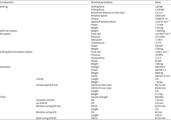
The MPDS was designed based on the framework mentioned in Section 2.2. Figure 6 depicts the design of the five primary subsystems. In operation, the air system, drilling fluid circulation system and generator can be positioned independently in the field and interconnected by hoses or power lines. In contrast, the drill rig and drill-rod module require a direct physical connection. Table 2 lists the key technical parameters of the MPDS, encompassing the drill rig, drill-rod module, air system, drilling fluid circulation system, generator and main downhole tools. These components are described in detail below.
Design of the MPDS.

Figure 6 Long description
The design of the MPDS is illustrated, highlighting five primary subsystems. At the top left, the generator is enclosed in a protective casing, positioned on a sled-like base. Below it, the air system is similarly enclosed, featuring various components within its structure. To the right of the air system, the drilling fluid circulation system is depicted, also on a sled, with multiple tanks and equipment visible. The central part of the diagram shows the drill rig, which is mounted on a larger sled and includes a drill-rod container. This section is more complex, with visible structural elements and a platform for operation. Each subsystem is labeled clearly, indicating its function within the overall design of the MPDS.
Key technical parameters of the MPDS.

Table 2 Long description
Components are listed with nominal parameters and values for the drill rig, drill rod module, air system, drilling fluid circulation system, generator, and tools. Drill rig values include drilling force up to 62 kN, pulling force up to 159 kN, mast movement distance up to 3.2 m, rotation speed up to 600 rpm, torque up to 3000 N m, wireline winch speed up to 129 m per minute, power about 75 kW, and weight 7270 kg. Drill rod module weight is about 2000 kg. Air system values include flow rate up to 10 Nm3 per minute, pressure up to 1.5 MPa, dew point down to minus 40 degrees C, temperature down to minus 5 degrees C, power 126 kW, and weight 7760 kg. Drilling fluid circulation system values include flow rate up to 100 L per minute, pressure up to 4 MPa, temperature down to minus 2 degrees C, power 43 kW, and weight 7300 kg. Generator values include voltage 400 and 230 V, power 300 kW times 2, and weight 9800 kg. Tools list casing with outer and inner diameter 148 and 127.5 mm, length 3 m, and weight about 20 kg; double wall drill rod with outer tube outer and inner diameter 89 and 73 mm and inner tube outer and inner diameter 49 and 38 mm, length 3 m, weight 27.5 kg, and tensile strength 499 MPa; snow or firn drill bit outer diameter 178 mm; ice drill bit outer diameter 110 mm; wireline coring drill rod outer and inner diameter 62 and 53 mm and length 3 m; wireline coring drill outer diameter 49 mm and length 3.85 m; and rock coring drill bit outer and inner diameter 67 and 44 mm.
4.1. Drill rig and drill-rod module
The newly designed drill rig is fully powered by a hydraulic system. This hydraulic system is driven by a 75 kW electric motor, delivering a hydraulic oil flow rate of 150 L min−1 at 25 MPa. To enable operation in cold environments, the hydraulic oil tank is fitted with an immersed electric heater, allowing the hydraulic oil to be heated prior to drill rig activation. Additionally, heating cables are installed along the hydraulic pipeline at the surface. When the hydraulic system is activated and the oil temperature becomes excessively high, a heat exchanger cooled by an air fan is employed to cool the hydraulic oil.
Generally, the drill rig has the same structure as a traditional fully hydraulic drill rig, which contains a base, mast, power head, tool winch, wireline winch, drill-rod clamp and a fixing device at the borehole mouth. The base is secured to the floor of a 20 foot container, with the mast, borehole mouth fixing device and wireline winch bolted atop it. To facilitate transportation, the mast is divided into main and secondary sections; during transit, the secondary mast retracts into the main mast, and during drilling, it extends outwards via a hydraulic cylinder. This design allows the mast to achieve a maximum lifting height of 6.35 m. The power head, mounted on the mast, moves along the guide rail of the main mast, driven by a hydraulic cylinder. At the top of the mast, a crown block directs the steel wireline from both the tool winch and wireline winch.
Two hydraulic cylinders are employed in the field to erect and lower the mast. The power head operates with a variable displacement piston motor, reaching a maximum rotation speed of 600 revolutions per minute (rpm). An integrated hydraulic chuck in the power head uses a spring to secure the drill rod and hydraulic force to release it. The tool winch is mounted at the rear of the mast to elevate the swivel. The wireline winch is used exclusively for subglacial bedrock drilling, utilising a 5 mm steel wireline and featuring an automatic rope-arranging mechanism. The drill-rod clamp not only secures the drill rod but also allows for screwing and unscrewing. It employs two hydraulic cylinders to hold the drill rod, accommodating a maximum diameter of 180 mm. The fixing device at the borehole mouth is installed on the base, with the drill-rod clamp attached to its top and the casing secured to its base. A waterway on the side of the fixing device permits excess drilling fluid to overflow during liquid-based drilling operations. All these drill rig components are manually operated via a single console, which also displays primary data collected by sensors from the air system and drilling fluid circulation system.
To reduce manual labour, a robotic arm has been designed to grasp and manipulate the drill rod. Mounted atop the container, the robotic arm moves bidirectionally along the guide rail, enabling motion in four directions: forward, backward, left and right. By utilising the robotic arm, power head and drill-rod clamp, the operator can efficiently manage the drill rod in the field. The robotic arm functions independently from other drill rig components and is controlled via a separate operation console.
The drill rig is modularly designed, allowing it to be disassembled into multiple parts for transportation. In the field, these components can be reassembled within a customised 20 foot container. The drill-rod module is also a modified 20 foot container and is designated for drill-rod storage. During transportation to Antarctica, the drill rods are stored separately and later placed on customised racks in the Antarctic field. Positioned adjacent to the drilling rig, the drill-rod module facilitates the transfer of drill rods. Both the drill rig and drill-rod module are then covered by a large tent in the field.
4.2. Air system
The air system generates dry, cold, high-pressure air and primarily consists of a compressor, receiver, freezing dryer, desiccant dryer, air cooler and multiple air filters. The compressor generates compressed air, which is directed into a receiver to attenuate pressure pulses. The compressed air is then dried using both the freezing dryer and desiccant dryer, reducing its dew point below −40°C. Once adequately dried, the compressed air is cooled by the air cooler to a temperature range of −10°C to 0°C. A sensor array, comprising a flowmeter, manometer, temperature sensor and dew-point hydrometer, continuously monitors the properties of compressed air prior to its injection into the borehole. The air system is divided into two parts, each weighing under 4 tonnes, facilitating easy field assembly and disassembly. The main parameters of the air system are presented in Table 2, with additional details available in Li and others (Reference Li2025).
4.3. Drilling fluid circulation system
The drilling fluid circulation system is structured into five functional components: drilling-fluid tank, cooling section, injection section, cutting-separation section and monitoring section. The drilling-fluid tank is segmented into circulation and stirring tanks to reduce weight and enhance transportation efficiency. These tanks are hydraulically connected via a pipeline. The cooling section comprises a refrigeration unit, heat exchanger and circulation pump. The circulation pump transfers drilling fluid from the circulation tank to the heat exchanger, where it is cooled to the desired temperature by the refrigerant. The refrigeration unit maintains the refrigerant at a low temperature. The injection section primarily features a drilling-fluid pump that pumps drilling fluid from the stirring tank into the borehole. The cutting-separation section utilises vibration sieve and vertical centrifuge to separate ice or rock cuttings from the drilling fluid. The monitoring section consists of two liquid-level gauges, a flowmeter, a manometer and a temperature sensor. The liquid-level gauges are positioned above the circulation and stirring tanks, whereas the remaining sensors are located at the drilling-fluid pump outlet to assess the properties of the fluid being injected into the borehole. Similar to the air system, the drilling fluid circulation system is segmented into two parts, facilitating easy assembly using bolts. Further design specifics of the drilling fluid circulation system are detailed in Li and others (Reference Li2025).
4.4. Generator
As illustrated in Fig. 7, two JCPC-C330 generators and one fuel tank are housed within a 20 foot container to supply power to the MPDS. Each generator has a power output of 300 kW; under normal operations, one generator powers the MPDS, while the second serves as a backup. The generators are adapted to function at −40°C, and the container features a specialised design to prevent snow ingress. Both generators draw fuel from a shared tank with a 1500 L capacity, and the liquid level of the tank is externally visible. For transportation, the generator system is disassembled into two generators and one container and can be readily reassembled on-site with mechanical assistance. The generator fuel can be either diesel or aviation kerosene.
Different types of drill bits: (a) snow/firn drill bit and ice drill bit made of steel; (b) ice drill bit made of PDC and tungsten carbide.

4.5. Tools
MPDS employs a variety of tools, including casings, swivels, downhole tools, fishing tools and a drilling fluid bailer.
4.5.1. Casing and swivel
The casing is constructed from unplasticised polyvinyl chloride (UPVC), which has half the density of aluminium alloy. The casing is connected via threads and sealed with silicone rubber O-rings. As detailed in Section 2.3, frozen water seals the gap between the casing and the borehole wall. To permit melting water to enter the gap, 20 small holes with a diameter of 30 mm have been drilled in the lower section of the casing. The top of the casing is suspended from the fixing device at the borehole mouth. MPDS utilises two types of swivels: one for double-wall drill rods and another for wireline coring drill rods. In ice drilling, only the swivel for double-wall drill rods is employed.
4.5.2. Downhole tools
The downhole tools primarily consist of double-wall drill rods, snow/firn drill bits, ice drill bits, wireline coring drill rods, wireline coring drills and rock coring drill bits. The double-wall drill rods are fabricated mainly from aluminium alloy to reduce weight, except for their connectors, which are made from stainless steel. They are connected via threaded connectors, and adjacent inner tubes are sealed with sealing rings. Additional details regarding the double-wall drill rods can be found in Bai and others (Reference Bai, Liu, Wang, Peng and Cai2024).
As shown in Fig. 7, the snow/firn drill bit, constructed from steel, facilitates air reverse circulation without coring and is equipped with three cutters featuring multiple small notches for enhanced cutting efficiency. There are three types of ice drill bits designed for ice drilling, made from steel, tungsten carbide and polycrystalline diamond compact (PDC). The steel-based ice drill bit maintains the same structure as the snow/firn drill bit, whereas the tungsten carbide variant also includes three cutters.
Bedrock sampling is conducted using the wireline coring drill, which can extract up to 3 m of bedrock core per run. The wireline coring drill employs a standard steel drill rod. For bedrock drilling, impregnated diamond bits are prepared, capable of drilling bedrock cores ∼44 mm in diameter.
4.5.3. Fishing tools
Two varieties of fishing tools are assembled for the MPDS. The first tool is the taper tap, engineered to retrieve double-wall and wireline drill rods that have been dropped into the borehole, specifically designed to match the dimensions of both drill rods. Additionally, three types of magnetic fishing tools with varying diameters are prepared to collect metallic debris from the borehole. These magnetic fishing tools are deployed in each of the three borehole spuds. The wireline coring winch is used to deploy and recover the magnetic fishing tools within the borehole.
5. Preliminary test and future improvements
5.1. Domestic test
The MPDS was initially tested in China after all subsystems were fabricated. Due to its substantial size and weight, the MPDS was unsuitable for ice drilling tests in China and was therefore utilised for soil and rock drilling. During domestic testing, only the fundamental functions of the MPDS were evaluated, revealing several issues, including improper mechanical connections and flawed structural design. These issues were resolved before the MPDS was dispatched to Antarctica. In domestic testing, both compressed air and tap water served as circulation media, and reverse circulation was achievable under significant load on the drill bit. Generally, the domestic tests illustrate the effective performance of the MPDS in soil and rock drilling operations.
5.2. Field test in Antarctica
The MPDS was transported to Antarctica for field testing during the 2024/25 season. The testing site (coordinates: 69°35′10.12″ S, 76°23′03.87″ E) lies on the northwest margin of the Princess Elizabeth Land Ice Sheet in East Antarctica, adjacent to the IBED drilling site in the 2023/24 season. Based on drilling data from the last season (Leitchenkov and others, Reference Leitchenkov2024a, Reference Leitchenkov2024b), the ice-sheet thickness at the drilling location is ∼545 m. As illustrated in Fig. 8, the field set-up included the MPDS alongside two fuel tanks, one drilling fluid tank, a living shelter, kitchen, toilet and a sledge for spare parts. In total, about 10 days were spent to assemble the MPDS and set up the field camp. All equipment was transported via sledge, resulting in a total material mass exceeding 120 tonnes at the site. In the field test, diesel was used as fuel. The field test lasted for ∼40 days, and a 110 m borehole was drilled. In the test, most of the MPDS was tested; however, a bedrock sample was not obtained.
Aerial view of the field camp in Antarctica.

5.2.1. General performance
In general, the drill rig performed well. The hydraulic system worked stably, and other components, such as the mast, power head, tool winch, wireline winch, drill-rod clamp and the fixing device at the borehole mouth, had not experienced malfunctions during the testing period. The robotic arm performed efficiently and significantly facilitated the movement of the drill rod within the drill rig container. Most functions of the drill rig, such as screwing and unscrewing the drill rod, as well as raising and lowering the drill rod, have been proven to be feasible. In the field test, the drill rig advances 3 m downwards in each run. Typically, the weight on bit (WOB) was maintained between 100 and 200 kg, while the rotation speed ranged from 70 to 200 rpm. During air drilling, the flow rate of compressed air was 9.3–12.4 Nm3 min−1 with the compressor pressure kept between 0.7 and 1.0 MPa. During liquid drilling, the flow rate of drilling fluid was controlled within 62–96 L min−1, whereas the pressure drop was maintained at 0.15–0.29 MPa (Li and others, Reference Li2025). The maximum penetration rate in snow and firn reaches 21 m h−1. The modularised design of the drill rig was also proven to be effective. The multiple parts of the drill rig can be reassembled within 2 days using mechanical assistance.
The air system kept working for 6 days before the air cooler was broken (Li and others, Reference Li2025). The continued working of the air system implies the feasibility of the air system’s principle. However, the failure of the freezing dryer and the desiccant dryer in drying the compressed air led to the breakage of the air cooler, which will be presented in detail in Section 5.2.3. Consequently, air drilling was halted. The air compressor and the sensors used in the air system demonstrated continuous stable performance during all drilling test operations.
Most components of the drilling fluid circulation system can work in the field, including the drilling-fluid pump, circulation pump, vertical centrifuge, circulation and stirring tanks, and the monitoring section. However, some of the components require upgrading to enhance operational efficiency; for example, the flow rate of the drilling-fluid pump should be adjustable by a variable-frequency drive for easy operation. More details on upgrading the drilling fluid circulation system can be found in Li and others (Reference Li2025). At the drilling site, the temperature of the drilling fluid remained below −2℃ at the surface, so the cooling section of the drilling fluid circulation system, comprising a heat exchanger and a refrigeration unit, was deactivated throughout operations. The main problem of the drilling fluid circulation system was the mismatch of the vibrating sieve with the drilling fluid. More details about the problem of vibration sieve can be found in Section 5.2.4 and Li and others (Reference Li2025).
The generator demonstrated stable operation under field conditions and exhibited reliable performance in low-temperature environments. The swivel worked well with compressed air but experienced slight leakage with drilling fluid. The double-wall drill rod fit well with other components of the MPDS. The wireline coring drill rods, wireline coring drills, rock coring drill bits and fishing tools were not tested because bedrock was not reached this season. The drill bits designed for snow/firn and ice drilling encountered significant challenges in establishing reverse circulation, which constituted the primary impediment to subglacial bedrock retrieval during this field season.
5.2.2. Problems during snow/firn drilling with air
During snow/firn drilling with air, many problems were encountered, and almost 1 month was spent to extend the borehole to 42 m. The main problem was the failure to establish air reverse circulation in the snow/firn drill bit, despite successful performance in soil and rock drilling during domestic testing. In this situation, the compressed air was injected into the inner tube of the double-wall drill rod and returned through the clearance between the borehole wall and the outer tube of the double-wall drill rod, instead of through the clearance between the inner and outer tubes of the double-wall drill rod. The permeable snow/firn layer allowed the returned compressed air to disperse into the surrounding strata (Whelsky and Albert, Reference Whelsky and Albert2016). Consequently, the flow rate of compressed air gradually decreased during upward flow. Additionally, the clearance between the borehole wall and the outer tube of the double-wall drill rod was significantly larger than that between the inner and outer tube of the double-wall drill rod, leading to insufficient flow velocity of compressed air to remove all ice chips from the borehole. Due to the relatively low flow velocity of the compressed air, some ice chips adhered to the borehole wall, while others settled at the borehole bottom (Fig. 9a). When the down-hole tool was withdrawn, the ice chips attached to the borehole could easily cause the drill to become stuck (Fig. 9b). Additionally, the snow/firn drill bit experienced periodic clogging (Fig. 9c). The primary reason was that the structure of the drill bit was not suitable for air normal circulation and the drill rig was difficult in controlling the load on the bit, leading to excessive force on the relatively soft snow/firn.
Problems encountered with air drilling: (a) ice chips attached to the borehole wall; (b) drill stuck; (c) clogging of the snow/firn drill bit; (d) frozen water in the inner tube of double-wall drill rod.

Additionally, the air system malfunctioned in the field. After several days of continuous operation, the freezing dryer and desiccant dryer failed to dry the compressed air to the expected dew point. Consequently, wet vapour in the compressed air flowed into the air cooler and froze into ice there, damaging the heat exchanger of the air cooler and causing the failure of compressed air cooling. In the field, a 140 m hose had to be buried in snow to cool the compressed air (Li and others Reference Li2025). However, due to the nonfunctional dryers and air cooler, the compressed air remained wet and warm before being pumped into the borehole. In this case, the water vapour in the compressed air froze into ice within the inner tube of the double-wall drill rod, which obstructed the circulation of airflow (Fig. 9d).
5.2.3. Success in casing cementing with meltwater
Despite multiple challenges during snow and firn drilling, the borehole reached a depth of 42 m, where snow density was ∼800 kg m−3. Then, 14 casing pipes were lowered into the borehole, and 0.9 m3 of meltwater at 9°C was pumped to the borehole bottom through a silicone hose. The meltwater in the borehole was observed to have completely frozen into solid ice after 84 hours. It is crucial to clarify that this interval represents the total time between meltwater injection and the start of drilling-fluid operations. Consequently, the actual duration required for the meltwater to freeze was certainly <84 hours. After meltwater freezing, the borehole depth became 30 m, which indicates that the lowest 12 m of the casing had been sealed by ice. After casing cementing, the borehole was deepened with drilling fluid from 42 to 110 m over 8 days. During this period, the maximum fluid pressure was ∼0.29 MPa, and the casing remained intact. In the future, experimental studies are suggested to test the reliability of using meltwater to seal the casing under higher drilling fluid pressures. In addition, the recovery of the casing for reuse in multiple boreholes should be considered.
5.2.4. Problems during ice drilling with drilling fluid
Faced with the various difficulties of air drilling, drilling fluid was adopted for further drilling once casing sealing was completed. Kerosene served as the drilling fluid in the field test. To improve the gel strength of the kerosene and its capacity to remove and suspend ice chips, organoclay was incorporated in the kerosene at a 3% concentration (Huang and others, Reference Huang, Lv, Sun, Liu, Wang and Wang2023, Reference Huang2025). Additionally, 1% sodium dodecylbenzene sulphonate was added to enhance organoclay’s dispersion stability. Compared to air drilling, ice drilling with liquid demonstrated comparatively superior performance. The borehole depth was increased from 30 to 110 m over 8 days, with a production drilling rate of 6–12 m d−1, which was significantly lower than expected. Two main factors affected the drilling rate. The primary issue was the frequent clogging of ice drill bits, requiring frequent clearing, which significantly reduced the penetration rate. Additionally, the drilling fluid circulation system operated inefficiently, leading to increased time spent on surface operations. Similar to air drilling, reverse circulation could not be established during ice drilling with liquid, resulting in all 80 m of ice being drilled using normal circulation. In our view, three main factors may explain the failure to establish reverse circulation. First, the design of the drill bit may be structurally inadequate, as it fails to prevent drilling fluid from leaking into the outer annulus of the drill rod. Second, the flow resistance in the central channel appears to be higher than that in the outer annulus. Third, the drill bit exhibited unstable behaviour at the bottom of the borehole, frequently jumping during operation.
Despite daily borehole depth advancement, liquid drilling encountered numerous issues. Initially, kerosene eroded the casing’s O-rings and promoted the expansion of the sealing ring (Fig. 10a). Nevertheless, no drilling fluid leakage was detected at the casing joints during liquid drilling. In field conditions, organoclay and other additives were gradually added to the kerosene in the stirring tank of the drilling fluid circulation system while being mixed using a 1.5 kW stirrer for <2 hours. However, thoroughly mixing the drilling fluid proved challenging, leading to inadequate dispersion of organoclay in kerosene. Over time, organoclay settled at the bottom of the drilling fluid tank (Fig. 10b), causing blockages in both the tank outlet and the circulation pipeline, which required periodic clearing. The settled organoclay also clogged the screen mesh pores of the vibrating sieve, hindering effective separation of ice chips (Fig. 10c). As shown in Fig. 10d and e, the primary issue during liquid drilling was the clogging of the ice drill bit, which can lead to a slow penetration rate in ice. Additionally, much time was required to retrieve the drill rod from the hole to clean the drill bit. Clogging of the ice drill bit occurred for two reasons: first, the drill bit is designed solely for reverse circulation; second, maintaining an appropriate load on the drill bit with the drill rig is challenging, and excessive drilling loads sometimes caused the drill bit to cut too deeply into the ice.
Problems encountered with liquid drilling: (a) erosion of drilling fluid on O-rings; (b) organoclay settled at the bottom of tank; (c) vibrating sieve did not work well with kerosene containing organoclay; (d) clogging of the ice drill bit made by PDC; (e) clogging of the ice drill bit made by tungsten carbide.

5.3. Future improvements
Overall, the main components of the MPDS, including the drill rig, drill-rod module, generator and drilling fluid circulation system, functioned. The main problems exposed through field practice are the following:
(1) Reverse circulation cannot be established in the snow/firn and ice drill bits.
(2) Precise control of the drill load on the bit proves challenging, frequently resulting in bit clogging incidents.
(3) The poor performance of both the freezing dryer and desiccant dryer resulted in the failure of the air cooler.
(4) The vibration sieve demonstrated incompatibility with the drilling fluid due to organoclay-induced clogging of screen mesh pores.
(5) The sealing rings installed on the casing and swivel demonstrated incompatibility with kerosene exposure, resulting in swivel leakage.
Preliminary field testing demonstrated that current technological capabilities of MPDS are insufficient, and significant improvements are necessary for future subglacial bedrock sampling. The following are key suggestions for future improvements of the MPDS.
(1) Redesign drill bits, including those for snow/firn and ice drilling, to accommodate reverse circulation drilling. Furthermore, subject the drill bits to laboratory ice drilling tests prior to deployment in Antarctica.
(2) Enhance the drill rig to precisely regulate the load applied to the drill bit, preventing clogging of the drill bit during drilling.
(3) Upgrade the air system by replacing the freezing dryer and desiccant dryer with higher-quality units. Additionally, improve specific components of the drilling fluid circulation system, including the drilling fluid pump, circulation pump and vibrating sieve (Li and others, Reference Li2025).
(4) Organoclay is unsuitable for enhancing the gel strength of kerosene; therefore, it should be excluded when drilling ice with kerosene.
(5) Construct all sealing rings and pipelines used in the MPDS from materials compatible with drilling fluid.
5.4. Summary
An MPDS was proposed and fabricated to obtain at least 10 m subglacial bedrock sample beneath 1000 m ice sheet in Antarctica. The MPDS consists primarily of a drill rig, drill-rod module, air system, drilling fluid circulation system and generator. All subsystems are modularly designed and can be disassembled into several parts with each weighing <4 tonnes, enabling helicopter transportation from icebreakers to Antarctic ice sheets. Upon arrival at the ice sheet, all subsystems can be integrated in a 20 foot container for transportation by sledge. The MPDS is engineered for ice drilling using reverse circulation by compressed air or drilling fluid, necessitating the use of a double-wall drill rod made of aluminium. Additionally, the MPDS utilises standard wireline coring drills to extract bedrock cores. When employing wireline coring drills, the outer tube of the double-wall drill rod functions as casing to prevent potential ice hydraulic fracturing events. The UPVC-fabricated casing separates permeable snow/firn from the borehole during liquid drilling and is designed to seal its base by freezing meltwater. Several fishing tools, such as the taper tap and magnetic fishing tool, are prepared to address unexpected drilling incidents.
The MPDS was preliminarily tested in China following fabrication and was subsequently tested in Antarctica during the 2024/25 season. In Antarctica, a 110 m borehole was drilled. During the field test, snow/firn drilling with compressed air was halted at a depth of 42 m due to the inability to establish reverse circulation. The tests revealed a suboptimal design of the snow/firn drill bit and unreliable performance of the air system. Casing sealing was successfully implemented by freezing meltwater at the borehole bottom. Although some melting water infiltrated into the surrounding snow/firn, the 12 m borehole at the bottom was completely solidified within 84 hours. Subsequently, drilling fluid was used to extend the borehole from 30 to 110 m over 8 days, demonstrating superior performance compared to air drilling. However, adding organoclay to kerosene caused numerous issues with drilling fluid circulation and ice chip separation. Additionally, the ice drill bit was ineffective in establishing reverse circulation, and clogging of drill bit occurred frequently. Overall, the principles and basic functions of the MPDS were feasible except for reverse circulation, but significant modifications are necessary for future subglacial bedrock drilling in Antarctica. Notably, some tools used for subglacial bedrock sampling, such as the ice-bedrock interface drilling tool, wireline coring drill and rock core drill bit, were not tested in Antarctica and require further testing. The upgraded MPDS will return to Antarctica for continued testing over the next 1–2 years.
Data availability statement
The data presented in this study are available on request from the corresponding author.
Acknowledgements
This work was supported by the National Key Research and Development Project of the Ministry of Science and Technology of China (No. 2021YFA0719104). We are grateful to the 41st Chinese Antarctic Expedition Team for logistical support of our field operations, especially thanks to Zhongshan Station and the aircraft team for providing the living facilities and snow vehicles in Antarctica.




 Open access

