I. INTRODUCTION
Boron carbide (B4C) is a covalently bonded, strategic material with an extremely high hardness (27.4–34.3 GPa) exceeded by only that of diamond and cubic boron nitride, a high melting point (∼2500 °C), a low density (2.52 g/cm3), a high elastic modulus (290–450 GPa), Reference Hugh1 and a high neutron absorption cross section (600 barns). Reference Suri, Subramanian, Sonber and Murthy2 The combination of these unique properties makes B4C a suitable material for applications, such as grinding media, cutting tools, nozzles for slurry pumping, personal armor, and nuclear shielding applications.
Recently, much attention has been paid to the unique thermoelectric properties of boron carbides because they have a large Seebeck coefficient, surprisingly low thermal conductivity, moderate electrical conductivity, and high-temperature stability. Reference Aselage, Emin, McCready and Duncan3–Reference Wood, Emin and Gray7 In particular, boron carbide's Seebeck coefficient is approximately 300 µV/K, Reference Aselage, Emin, McCready and Duncan3–Reference Guan, Gutu, Yang, Yang, Zinn, Li and Xu6 thermal conductivity is approximately 0.05 J/K s cm Reference Emin and Aselage5,Reference Wood, Emin and Gray7 and thermal diffusion is approximately 0.01 cm2/s near room temperature, despite being hard and stiff with very high sound velocities (106 cm/s). Reference Guan, Gutu, Yang, Yang, Zinn, Li and Xu6,Reference Emin8 The dimensionless thermoelectric figure-of-merit (ZT = α2 σ/κ) of boron carbide (where σ is electrical conductivity, κ is thermal conductivity, and α is the Seebeck coefficient) on the order of one was reported, whereas ZT ≫ 1 has also been predicted at high temperatures. Reference Guan, Gutu, Yang, Yang, Zinn, Li and Xu6,Reference Wood, Emin, Aselage, Beckel, Howard and Wood9 These distinctive properties make boron carbide a strong candidate for high-temperature thermoelectric power generation. Reference Guan, Gutu, Yang, Yang, Zinn, Li and Xu6,Reference Emin8–Reference Wood12 Due to its large Seebeck coefficient, boron carbides can also be used as neutron detectors, batteries, etc. In particular, 10B is an excellent absorber of thermal neutrons. Reference Emin and Aselage5
Control of the grain size and morphology in the synthesis of B4C powder is required to improve the sinterability and properties of ceramics. Because of the rigid covalent bond and corresponding low self-diffusion coefficient, the sintering of pure boron carbide is very difficult. Reference Du, Zhang, Wang, Wang, Wang, Wang and Fu13 On the other hand, boron carbide can undergo considerable grain coarsening with little densification during sintering Reference Schwetz and Grellner14–Reference Dole, Prochazka and Doremus17 due to the surface-to-surface mass transport as a consequence of mass-transport in the absence of densification. Reference Greskovich and Rosolowski15,Reference Larsson, Axen and Hogmark18
Dense boron carbide ceramics cannot be obtained via pressureless sintering with commercial B4C powder unless using super-fine powder Reference Thevenot19–Reference Roy, Subramanian and Suri21 and critical heat treatment at very high temperatures (usually beyond 2200 °C). Reference Du, Zhang, Wang, Wang, Wang, Wang and Fu13,Reference Li, Jiang, Zhang, Lin, Chen and Huang22,Reference Yin, Huang, Liu, Zhang and Jiang23 Hot-pressing is therefore an essential technique for obtaining dense boron carbide ceramics. Many literature studies have reported the effects of B4C powder particle size Reference Xian-Wu, Zhi-Xiao, Wei-Min, Zheng-Yi and Hao24 and hot-pressing parameters Reference Ostapenko, Slezov, Tarasov, Kartsev and Podtykan25–Reference Yue, Chen, Zhao, Wang and Ru28 on the microstructure and properties of hot-pressed boron carbide. Reference Du, Zhang, Wang, Wang, Wang, Wang and Fu13
Sintering additives have been used to increase the volume and grain boundary diffusion and, therefore, to promote densification at lower temperatures. For instance, fine grained boron carbide powders can be sintered up to 95% of the theoretical density via pressureless sintering with the additions of free carbon as a sintering aid. Reference Greskovich and Rosolowski15,Reference Larsson, Axen and Hogmark18
Other sintering additives, such as C, B, TiB2, Si, Al, Mg, SiC, SiC + Al, TiB2 + C, TiO2, ZrO2, TiC, WC, BN, AlF3, Al2O3, W2B5, Fe, Ti, B, Mg, Co, Ni, Al, Cu, etc., have also been used, with various degrees of improvement in sintering behavior and mechanical properties. Reference Schwetz and Grellner14,Reference Roy, Subramanian and Suri21,Reference Mashhadi, Taheri-Nassaj and Sglavo29–Reference Kim, Koh and Kim38 However, the sintering additives can cause secondary phases to appear, which can have significantly negative effects on the mechanical properties of the sintered ceramic. Reference Hayun, Kalabukhov, Ezersky, Dariel and Frage39
There are many different methods for the synthesis of B4C particles in the literature. The main technological differences between these various methods involve the types of precursors, process temperatures, unit operations, scale at which they can be carried out and, most importantly, the particle size, size distribution, and morphology of the final products. For instance, B4C can be commercially synthesized via carbothermic reduction of boric oxide (B2O3)/boric acid (H3BO3). Reference Suri, Subramanian, Sonber and Murthy2,Reference Alizadeh, Taheri-Nassaja and Ehsani40 However, this commercial process requires high operation temperatures (>2000 °C), further purification and grinding of the resultant materials in the form of chunks and coarse particles before use in industrial applications. The grounding operation may introduce additional impurity to the final products. One of the alternate commercial methods for the production of B4C is magnesiothermic reduction of boron anhydride in the presence of carbon. However, the high cost of the precursor materials and the contamination of the magnesium compounds in the final products make this method not feasible for most commercial productions. Reference Suri, Subramanian, Sonber and Murthy2
There have been many attempts to develop new processes to produce B4C at much lower temperatures than that of carbothermic reduction processes. For instance, Yanase et al. Reference Yanase, Ogawara and Kobayashi41 used the condensation of poly(vinyl alcohol) and boric acid as a precursor. Crystalline B4C powder with residual carbon was synthesized by the pyrolysis precursor in air at 600 °C for 2 h, followed by heat treatment in Ar flow at 1300 °C for 5 h. Welna et al. Reference Welna, Bender, Wei, Sneddon and Allcock42 developed a process for the fabrication of nanoscale porous B4C/C, ceramic-fiber matrices through electrostatic spinning and pyrolysis of poly(norbornenyldecaborane). Pyrolysis was performed under argon at 1650 °C. Hadian et al. Reference Hadian and Bigdeloo43 performed a modified sol–gel process, where the starting materials, i.e., boric acid and citric acid compositions, were adjusted. Micron-sized B4C powder was obtained by heating the pyrolyzed gel precursor powder (boric acid with citric acid with a ratio of 2.2) at 1500 °C under vacuum for 2.5 h. B4C particles of several microns in size were synthesized via the heat treatment of solid precursor material obtained by sulfuric acid dehydration of a sugar and boric acid mixture at 1500 °C under Ar gas flow. Reference Ergun and Yilmaz44
Ergun et al. used low cost sucrose-based precursor materials to synthesize pure B4C, as well as in situ B4C/TiB2, B4C/ZrB2, and B4C/SiC composites at lower temperatures than the temperatures needed for the carbothermic reduction method. Reference Ergun and Yilmaz44,Reference Cakir, Ergun, Sahin and Erden45 Tao and co-workers Reference Tao, Dong, Wang, Zhang, Nelson and Li46 reported that B4C-nanowire/carbon-microfibre hybrid structures could be fabricated using a cotton T-shirt as both the template and carbon source. They used nickel nitrate hexahydrate [Ni(NO3)2·6H2O] as a catalyst to decrease the B4C formation temperature to as low as 1160 °C.
Most of these processes seem to remain at the level of scientific curiosity, and there is little literature regarding their commercialization. However, the important points raised in the literature are as follows: (i) boron carbide can be synthesized at lower temperatures than those used in carbothermic reduction processes; (ii) catalysts such as Ni may promote B4C formation at lower synthesis temperature; (iii) particles obtained are micron-sized, most probably due to the coarsening tendency of boron carbide at high temperature. Reference Suri, Subramanian, Sonber and Murthy2,Reference Dole, Prochazka and Doremus17,Reference Tao, Dong, Wang, Zhang, Nelson and Li46 Any contribution to developing a method making it possible to decrease the synthesizing temperature of B4C, allowing for doping different elemental species to modify its sinterability or other physical or electrical properties and for lowering the particle size to nanometric dimensions, is appreciated by people both in research and industry. Nevertheless, the ideal process seems to have high heating and cooling rates to/from the reaction temperature, as well as direct conversion to fine particles without any need for further processing.
Aerosol processes have been integrated into continuous production processes to synthesize particulate ceramics. Spray pyrolysis, as one of the most widely used aerosol processes, has been used to produce particles with sizes ranging from less than a micron to several micrometers. Reference Messing, Zhang and Jayanthi47–Reference Lenggoro, Hata, Iskandar, Lunden and Okuyama53 The physical and chemical flexibility of spray pyrolysis processes permits controlled synthesis of advanced ceramic particles, such as oxides, Reference Lenggoroa, Itoha, Iidab and Okuyama54–Reference Eslamian and Ashgriz57 non-oxides Reference Cho and Rhee58,Reference Pingali, Rockstraw and Deng59 and in situ composite particles. Reference Xiao, Gonsalves, Strutt and Klemens60–Reference Yang and Kim62 Messing et al. Reference Messing, Zhang and Jayanthi47 explained the major steps in solid particle production with spray pyrolysis.
Briefly, the spray pyrolysis method is based on the droplet-to-particle conversion route. First, discrete droplets obtained by atomizing the precursor solution are suspended in a carrier gas. Later, these aerosol droplets can be introduced into a series of successive reactors in the production line. In the first step, the solvent is evaporated out of each individual droplet, forming precipitates. In the next step, the remaining precipitates undergo thermolysis at higher temperatures to invert them into microporous particles by direct pyrolysis or by in situ reactions with another gas. Finally, these microporous particles are sintered to form dense particles. Reference Messing, Zhang and Jayanthi47
One of the most important advantages of spray pyrolysis is that reactions occur in each individual droplet, providing better control of uniformity in the chemical concentrations and particle sizes of the final products. Reference Messing, Zhang and Jayanthi47,Reference Ozcelik and Ergun48,Reference Lenggoro, Hata, Iskandar, Lunden and Okuyama53
The sizes and size distribution of the final particles are mainly dependent on the initial sizes and size distribution of the liquid droplets in the carrier gas, the solute concentration in the precursor solution and, in some cases, particle break-up during drying and/or pyrolysis. Particles made by following this route can be either solid or porous depending on the solute concentration in the precursor solution and drying speed of the atomized liquid droplets. Reference Messing, Zhang and Jayanthi47,Reference Swihart63,Reference Pratsinis, Skillas, Maisels, Kodas, Kulkarni, Baron and Willeke64
Pneumatic atomization is one of the convenient methods for industrial liquid droplet production because of its high production rate (throughput) compared to other atomization techniques. On the other hand, its droplet size distribution is rather broad, which can result in a broad size distribution in produced particles. Nevertheless, the performance of the pneumatic nebulizer has been regarded as one of the most crucial parameters determining the quality of an aerosol in terms of the droplet size and size distribution of an aerosol and liquid flow rate. Reference Ozcelik and Ergun48 In recent years, many high-performance nebulizers, such as the high efficiency pneumatic nebulizer, Reference Olesik, Kinzer and Harkleroad65,Reference Burgener66 the microconcentric nebulizer, Reference Augagneur, Medina, Szpunar and Lobinski67 the direct injection nebulizer, Reference Liu, Lopez-Avila, Zhu, Wiederin and Beckert68 and the oscillating capillary nebulizer, Reference Wang, May, Browner and Pollock69 have been developed and investigated for their characteristics, particularly for inductively coupled plasma (ICP) mass spectroscopy. Moreover, the utilization of spray chambers has further increased the quality of the aerosols, removing large droplets from the nebulizer aerosol. Reference Sharp70
The objective of the current study was to develop a continuous flow process based on the spray pyrolysis technique to synthesize sub-micron-sized B4C particles at relatively lower temperature than that of carbothermic reduction processes without any need for a grounding process to decrease the particle size. To realize this objective, boric acid and sucrose-based low cost precursor solutions were used in an aerosol process using a home-made spray pyrolysis system. To the best of our knowledge, the approach described in this study has not been used before. The effect of Ni addition to the precursor solution as a catalyst on the particle composition and production temperature of B4C was also investigated. Moreover, a control set of samples was prepared and heat-treated with the same experimental parameters to compare their microstructure and morphology with those synthesized via the spray pyrolysis method. Subsequently, the material characterizations were performed via x-ray diffraction, Fourier infrared spectroscopy, scanning electron microscopy, and thermal analysis methods.
The experimental system was modeled, and simulations were performed using the computational fluid dynamics (CFD) software. The temperature distribution determined from the simulations was used to evaluate the effects of reactor temperature on the morphologies of the synthesized particles.
II. MATERIAL AND METHODS
A. Sample preparation
Boric acid (H3BO3), used as a source of boron, was dissolved in methanol (CH3OH) at a concentration of 0.55 M. Sucrose (C12H22O11), used as a source of carbon in the precursor solution, was dissolved in distilled water (d-H2O) at a concentration of 2.92 M. Next, these two solutions were mixed together using a magnetic stirrer at given molar ratios, listed in Table I. This mixture was used as the precursor solution for spray atomization in the particle synthesis via spray pyrolysis. Nickel nitrate [Ni(NO3)2·6H2O] was also added into the selected precursor solution as a catalyst. The molar ratio of boron increased for nickel based precursors because of using catalyst according to Ref. Reference Tao, Dong, Wang, Zhang, Nelson and Li46.
Compositions of precursor solutions and their treatment temperatures.

A set of control samples was prepared from this precursor solution (given in Table I) via oven drying at 70 °C for several days, followed by heat treatment in an argon atmosphere for 1 h. The heat treatment temperatures for the boron–carbon-based samples in the control set were 1100 and 1550 °C, whereas the reaction temperature was 1230 °C for Ni-containing precursors, which was not higher than the melting point of nickel boride compounds Reference Burke and Danheiser71 that could form during heat treatment.
B. Spray pyrolysis system
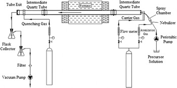
The schematic representation of the home-made experimental system was shown in Fig. 1. The details of the experimental system are discussed elsewhere. Reference Ozcelik and Ergun48 The atomization unit consisted of a pneumatic high-performance nebulizer Teflon Mira Mist (Burgener Research Inc., Canada) and a conical spray chamber (Borucam Ltd. Sti, Turkey). The operation of the nebulizer is based on an enhanced parallel-path approach in which a spout at the gas exit interacts with the liquid solution in the central portion of the gas stream where the gas energy was highest. The aerosols produced by this nebulizer were finer than those produced by a conventional parallel-path nebulizer, in which the liquid and gas interaction takes place at the edge of the sample capillaries. Reference Burgener66,Reference Todoli and Mermet72 The nebulizer was operated at a pressure of 2.5 bar and a flow rate of 0.5 L/min. The precursor solution was pumped into the nebulizer via a peristaltic pump (NE-9000, New Era Pump Systems Inc., Farmingdale, New York) at a flow rate of 2.4 mL/min.
Schematic diagram of the experimental apparatus.

The nebulizer was mounted in the inlet of the conical spray chamber. Coarser droplets are removed from the aerosol via impact with the chamber walls and with glass beads positioned at the center portion of the spray chamber, as a result of droplet inertia, gravitational settling, and turbulence. The reported values for the primary mean aerosol diameter obtained from a high-performance nebulizer are approximately 11 μm. The mean diameter may be approximately 3 μm after impact with a spherical surface. Reference Todoli and Mermet73 Condensed eluents removed from the spray chamber at the bottom of the chamber and drained into a precursor solution reservoir for recycling back into the nebulizer. Only mist with relatively finer droplets was allowed to leave the spray chamber and was transported into the tubular system. The flow rate of the finer droplets was approximately 0.12 mL/min.
The aerosol was transported into the reaction chamber via an intermediate quartz tube by high purity argon flow with a flow rate of 5 L/min that served as a carrier gas. The reactor chamber consisted primarily of an aluminum tube with an inside diameter of 7.5 cm and a length of 130 cm that was placed in a tube furnace (Protherm, PTF 16/75/610, Turkey) with a temperature control sensitivity of ±1 °C. During the process, the furnace was maintained at the desired pyrolysis temperature of 1100, 1230, and 1550 °C.
Another quartz intermediate tube was used to connect the tubular reactor outlet to the particle collector unit. High purity argon at a pressure of 2.5 bar and a flow rate of 3 L/min was introduced just before the particle collector as a quenching gas. The flow of carrier gas inside the tubular system was maintained via a vacuum pump that was mounted to the particle collector outlet.
The particles generated were collected at two different locations at the outlet of the experimental system: (i) on the wall surface inside the tube exit (called the tube exit) and (ii) in a distilled-water-filled glass flask (called the flask collector) at the outlet of the tube system.
C. Materials characterization
Thermal analysis (thermogravimetric [TGA] and differential scanning calorimeter [DSC]) of the dried precursor solution (the precursor solution [given in Table I] was dried at 70 °C for several days) was carried out using a Netzsch STA Jupiter 449 C (NETZSCH Thermal Analysis, Selb, Germany) from room temperature to 1200 °C. The analysis was performed in an argon atmosphere (40 mL/min) with a rate of heating of 20 °C/min.
The phases of the particles were determined via X-ray diffraction (XRD) analysis using a PANalytical X'pert Powder type PW3040 diffractometer (PANalytical, Almelo, The Netherlands) operated with Cu–Kα radiation (λ = 1.5406 nm) produced at 40 kV and 35 mA. Scanning was performed at diffraction angles (2θ) between 20 and 70° in increments of 0.044° for 1 s. The diffraction signal intensity was monitored throughout the scan and was processed using the X'pert High Score plus 2.2b software.
The surface morphology of the synthesized particles was investigated using a scanning electron microscope (SEM; Zeiss EVO/MA10, Carl Zeiss AG, Jena, Germany).
Attenuated total reflectance-Fourier transform infrared spectroscopy (ATR-FTIR) spectrum analysis was performed using an Alpha FT-IR Platinum ATR (Bruker Corporation, Ettlingen, Germany) in the range of 4000–400 cm−1 and a resolution of 4 cm−1.
D. Simulation of the experimental system
The tubular system used in the spray pyrolysis apparatus was positioned horizontally. The effect of buoyancy was expected to be asymmetrical flow in the carrier gas in the tube. Therefore, a half-cylindrical 3D model was used to describe the flow along the tubular system so that gravity could be taken into account by the buoyancy effect. Simulations were carried out using the commercial ANSYS Fluent v.12.0.1 software.
In the simulations, the nebulizer and carrier gases were assumed to be ideal, and their temperature-dependent properties were taken into account accordingly.
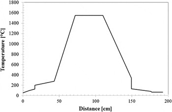
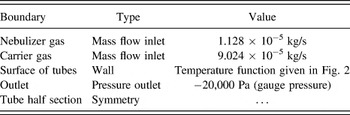
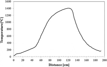
The wall, mass flow inlet, pressure outlet, and symmetry were used as boundary conditions. The wall boundary condition represents the surface of the tube wall, and the tube wall temperatures change along the tube axis. The temperatures at the tube wall were measured with thermocouples at 20 different points during experiments, and these measured temperatures (Fig. 2) were used in the analysis to define temperature functions along the tube axis. The pressure outlet boundary condition was used to define the static pressure at the flow outlet, which was maintained at a gauge pressure of −20 kPa during the experiments using a vacuum pump. The flow rate of the nebulizer and carrier gas was known (given in Sec. II. B), and thus the mass flow inlet boundary condition was used at the inlet of the system for the nebulizer and carrier gas. Specifying the mass flow rate permits the total pressure to vary in response to the interior solution. 74 The physical geometry of the tubular system and the expected pattern of the flow/thermal solution have mirror symmetry. Thus, a half model of a tubular system was constructed, and its boundary condition was given as symmetry. The boundary conditions are summarized in Table II.
Profile of the temperatures measured on the tube walls for reactor temperature of 1550 °C.

Boundary conditions for the CFD simulations.

The nodal temperature and velocity values were determined from the simulations. The distance between two nodes was read from the coordinates of the nodes. The average velocity was calculated by averaging the velocities at two nodes. Similar calculations were performed to determine temperatures in the simulations.
III. RESULTS
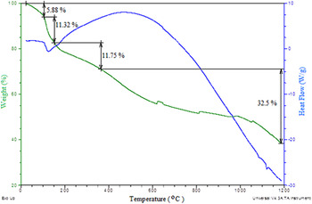
The DSC graph of the dried-only boron-based sample is presented in Fig. 3. In this graph, four different sections could be distinguished, with pronounced segments falling between: (i) 24–110 °C, weight loss in this range is probably connected to the evaporation of water in open defects; (ii) 110–170 °C, removing residual water from intercrystalline fields and evaporation initiation of some boric acid; (iii) 170–370 °C, proceeding of boric acid evaporation and possible decomposition of boric acid to boric oxide, as discussed in Ref. Reference Saidaminov, Maksimova and Avdeev75; and (iv) 370–1200 °C, endothermic reactions take place with great weight loss in the sample, which may be due to the combustion of excessive carbon, occurring in successive boron–carbon reactions at high temperatures. A peak in the range of 380–540 °C in the DSC curve may be an indication of phase changes during pyrolysis. Reference Khanra76
TGA–DSC curves of dried boron-based precursor solution.

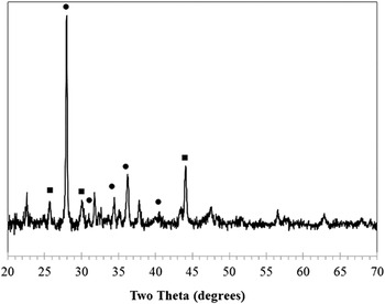
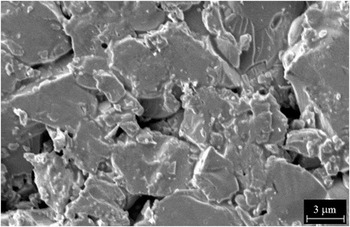
The XRD pattern of BCS-1100 in the control set prepared with a heat treatment at 1100 °C is given in Fig. 4. The pattern shows the presence of B2O3 as the major phase and C as the minor phase. B2O3 should have been formed by the conversion of H3BO3 in the precursor during heat treatment. However, no B4C phase was identified. The SEM photo of BCS-1100 samples is shown in Fig. 5. The particles had filled, solid non-spherical shapes. The average diameter of the particles was approximately 6 µm.
XRD pattern of the control set of the sample obtained at a heat treatment temperature of 1100 °C (BCS-1100). (●) B2O3; (■) C.

SEM analysis of the control set of the sample obtained at a heat treatment temperature of 1100 °C.

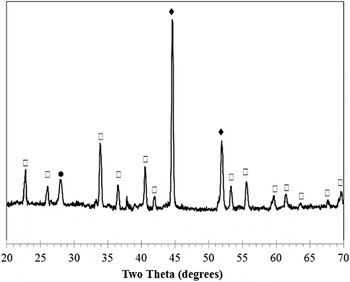
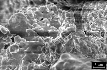
The XRD pattern of NCS-1230 in the control set prepared by heat treatment at 1230 °C is given in Fig. 6. Metallic Ni seemed to be the dominant phase in the sample. Moreover, B2O3 and nickel borate [(Ni3)(BO3)2] were also identified as secondary phases. However, no B4C formation was observed in the samples. Moreover, no catalyzing effect of Ni was observed, promoting a decrease in the B4C formation temperature to the level of 1230 °C, in contrast to the results given in Ref. Reference Tao, Dong, Wang, Zhang, Nelson and Li46. As shown in the SEM photo in Fig. 7, NCS-1230 samples in the control set had complex irregular geometries.
XRD pattern of the control set of the sample obtained at a heat treatment temperature of 1230 °C (NCS-1230). (●) B2O3, (♦) Ni, (□) (Ni3) (BO3)2.

SEM analysis of the control set of the sample obtained at a heat treatment temperature of 1230 °C (NCS-1230).

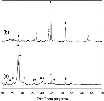
The XRD patterns of the NSP-1230 particles collected from the tube exit and flask collector at 1230 °C using the spray pyrolysis method are given in Fig. 8. H3BO3 and B2O3 converted from H3BO3 in the precursor solution were the dominant phases in the particles collected from the tube exit because of low reaction temperature [Fig. 8(a)]. Ni, C, and boron hydride (B10H14) peaks were also observed in the XRD patterns. On the other hand, although metallic Ni seemed to be the dominant phase, a small amount of nickel oxide (NiO) was also observed in the particles collected from the flask collector [Fig. 8(b)].
XRD patterns of the particles obtained at (a) the tube exit, and (b) the flask collector using the spray pyrolysis method at 1230 °C (NSP-1230).

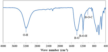
Figure 9 shows the FTIR spectra of the NSP-1230 particles collected from the tube exit at the reactor temperature of 1230 °C. The absorption band centered approximately at 3200 cm−1 was attributed to O–H stretching vibration. The bands centered at approximately 1450, 1190, and 1015 cm−1 were attributed to B–O stretching vibration, B–O–H bending, and B–O–C bending vibration, respectively. Reference Yanase, Ogawara and Kobayashi41,Reference Kakiage, Tominaga, Yanase and Kobayashi77–Reference Mondal and Banthia79 According to the band at 1015 cm−1, a complex between boric acid and sucrose and B4C may form by reaching sufficient pyrolysis temperature. Reference Yanase, Ogawara and Kobayashi41,Reference Pilladi, Ananthasivan, Anthonysamy and Ganesan78,Reference Mondal and Banthia79
FTIR spectra of the particles obtained from the tube exit using the spray pyrolysis method at 1230 °C (NSP-1230).

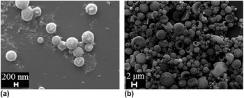
SEM photos of the particles obtained from the tube exit and the flask collector using the spray pyrolysis method at 1230 °C (NSP-1230) are given in Figs. 10(a) and 10(b), respectively. The particles collected from the tube exit had spherical morphology and the average diameter was approximately 0.6 μm [Fig. 10(a)]. Moreover, holes on the outer surface of the particles collected from the flask collector could have been formed because of the insufficient sintering at the reactor temperature of 1230 °C [Fig. 10(b)]. The average diameter of particles collected from the flask collector was approximately 230 nm, and primary particles in the form of agglomerations of the smaller particles were approximately 2 μm in diameter.
SEM images of the particles obtained from (a) the tube exit and (b) the flask collector using the spray pyrolysis method at 1230 °C (NSP-1230).

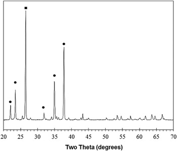
The XRD pattern of BCS-1550 in the control set prepared using heat treatment at 1550 °C is given in Fig. 11. According to the XRD pattern, B4C phases associated with an excessive amount of C were observed in the structure. The SEM photo of BCS-1550 in the control set is given in Fig. 12. The particles had irregular morphologies with average sizes of approximately 30 µm. This large particle size can be considered to be the evidence for a possible exaggerated grain growth during heat treatment. Reference Dole, Prochazka and Doremus17,Reference Larsson, Axen and Hogmark18
XRD pattern of the control set of the sample obtained at a heat treatment temperature of 1550 °C (BCS-1550). (●) B4C, (■) C.

SEM analysis of the control set of the sample obtained at a heat treatment temperature of 1550 °C (BCS-1550).

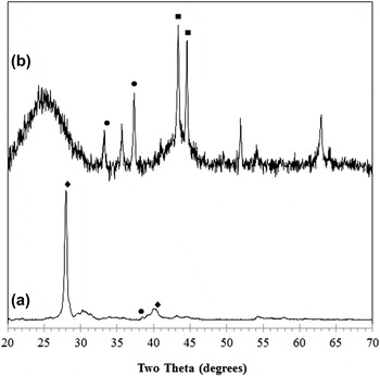
The XRD patterns of the BSP-1550 particles collected from the tube exit and flask collector at 1550 °C using the spray pyrolysis method are given in Figs. 13(a) and 13(b), respectively. B2O3 was the major phase observed in the particles collected from tube exit. A slight amount of B4C was also detected [Fig. 13(b)]. On the other hand, the amount of B4C was much more dominant in the particles collected from the flask collector, associated with an excessive amount of C in the form of amorphous and crystalline phases [Fig. 13(b)].
XRD patterns of the particles obtained at (a) the tube exit, and (b) the flask collector using the spray pyrolysis method at 1550 °C (BSP-1550). (●) B4C, (♢) B2O3, (■) C.

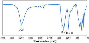
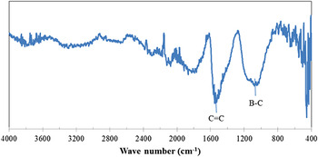
Figures 14 and 15 show the FTIR spectra of the BSP-1550 particles collected from the tube exit and the flask collector, respectively. The band centered at approximately 3200 cm−1 was attributed to O–H stretching vibration. The absorption peak at 1450 cm−1 could be assigned to B–O stretching vibration, and the peak at 1190 cm−1 was attributed to the absorption band of B–O–H. Reference Kakiage, Tominaga, Yanase and Kobayashi77,Reference Pilladi, Ananthasivan, Anthonysamy and Ganesan78 The shift of the B–O stretching vibration band (1472 cm−1) for H3BO3 (Ref. Reference Parsons and Milberg80) to a lower wave number was observed for particles collected from the tube exit, indicating that B–O–C bonds were formed. Reference Kakiage, Tominaga, Yanase and Kobayashi77 According to the FTIR spectrum of particles collected from the flask collector (Fig. 14), the peak at 1020 cm−1 corresponded to the B–C bond. Reference Romanos, Beckner, Stalla, Tekeei, Suppes, Jalisatgi, Lee, Robertson, Firlej, Kuchta, Wexler, Pfeifer and Yu81
FTIR spectra of the particles obtained from the tube exit using the spray pyrolysis method at 1550 °C (BSP-1550).

FTIR spectra of the particles obtained from the flask collector using the spray pyrolysis method at 1550 °C (BSP-1550).

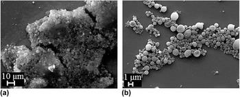
The SEM photo of the BSP-1550 particles collected from the tube exit and flask collector at 1550 °C using the spray pyrolysis method is given in Fig. 16. The particles collected from the tube exit were nearly spherical in shape and had aggregates approximately 0.35 μm in diameter [Fig. 16(a)].
SEM images of the particles obtained at (a) the tube exit, and (b) the flask collector using the spray pyrolysis method at 1550 °C (BSP-1550).

On the other hand, most of the particles collected from the flask collector were in the form of hollow spheres and aggregates of nanoparticles [Fig. 16(b)]. Primary particles, with an average size of 70 nm, showed a tendency to coalesce, perhaps due to the large surface energy and/or sintering with neighborhood particles. Secondary particles with an average size of 1.5 μm formed via sintering of the coalescent nanoparticles. These larger secondary particles had small holes on their surfaces. Reference Kim and Kim82,Reference Milosevic, Mancic, Rabanal, Gomez and Marinkovic83
The temperature profiles along the tube axis determined from the simulation are illustrated in Fig. 17 for the reactor temperatures of 1550 °C. Increasing the reactor temperature clearly affected the temperature distribution along the tube axis. The maximum temperature appeared to be shifted to the exit side and was an average of 100 °C lower than the setting temperature.
Temperatures along the tube axis determined from CFD simulations for the case in which Ar was used as the carrier gas for reactor temperatures of 1550 °C.

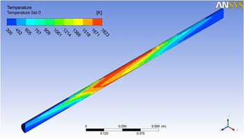
Figure 18 shows the temperature distributions, on a vertical plane of symmetry, of the tubular system, obtained from the simulation. The temperature of the upper surface of the tube seemed to be higher than that of the bottom surface, which was consistent with the experimental measurements. As the carrier gas passes through the heated zone and its temperature increases, its velocity vector gains an upward component because of the gravity effect (gravity acceleration was along the y-axis). Accordingly, hotter carrier gas was expected to exhibit upward motion in the y-direction given its motion in the x-direction. This could explain the difference in temperature between the upper surface and the lower surface of the tube. The gas flowing near the wall of the tube reached the setting temperature. However, the temperature of gas traveling along the axis reached approximately 1450 °C.
Temperature distributions on a vertical plane of symmetry of the tubes for reactor temperatures of 1550 °C.

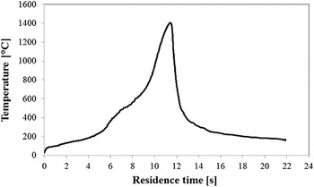
The residence time of the particles is one of the important parameters affecting the quality of the particles in the tubular reactor system. This residence time determines the amount of time particles spent in the spray pyrolysis stages, e.g., evaporation, thermolysis, and sintering. For instance, slower evaporation in the solvent evaporation step is necessary to avoid the development of a sharp solvent concentration gradient and solvent boiling within each individual droplet prior to precipitate formation. In CFD simulations, the residence time between two nodes is calculated as the ratio of the distance to the average velocity. These data were used to construct a profile of the temperature versus the residence time, shown in Fig. 19. The calculated residence time was approximately 22 s. The residence time is a function of the droplet velocity, which is highly dependent on the type of nebulizer used during atomization.
Temperature–residence time profiles for reactor temperatures of 1550 °C.

IV. DISCUSSION
The results of XRD analysis in the control samples containing boric acid and sucrose showed that there was no B4C formation upon heat treatment at 1100 °C; however, B–C bond formation Reference Yanase, Ogawara and Kobayashi41,Reference Pilladi, Ananthasivan, Anthonysamy and Ganesan78,Reference Mondal and Banthia79 was identified in the FTIR analysis. The resultant microstructure can be considered boronated amorphous carbon. Particularly, boronated tetrahedral amorphous carbon can be recognized as having a high fraction of sp3 bonding (80–85%) with “diamond like” properties and can be used in applications where wear resistance is required. Reference Chhowalla, Yin, Amaratunga, McKenzie and Frauenheim84,Reference Vishwakarma, Prasad, Subramanyam and Ganesan85
When the treatment temperature was increased to 1550 °C, a boron carbide phase with an excessive amount of free carbon was observed in the final microstructure in the control samples. It should also be noted that particle coarsening was also observed, in agreement with Ref. Reference Dole, Prochazka and Doremus17, which reported the coarsening tendency of boron carbide at high temperatures.
As the DSC analysis of the control set showed, there is a continuous evaporation of boric acid during the heating process, starting at temperatures as low as 170 °C. This evaporation process causes a continuous loss of boric acid and a consequent loss of the stoichiometry in the precursor at the expense of boric acid until the reaction temperature for the formation of B4C is reached.
Nevertheless, a complete reaction between carbon and boric acid to form B4C may not be expected because the reaction by-product, e.g., carbon monoxide, carries volatile boric species away from the reaction site. This transport mechanism can result in the final boron carbide product having an excess amount of free carbon residue. Reference Jung, Lee and Kim86
In a typical tube furnace reactor, similar to the ones used for the heat treatment of the control samples, such a heat treatment cycle can take approximately 5–6 h. Slow heating and cooling processes can promote the evaporative loss of boric acid. Moreover, synthesized B4C particles may coarsen into large irregular morphologies during this long heat treatment cycle.
With the utilization of a low cost precursor solution, the contained boric acid and sucrose spherical sub-micron-sized B4C particles were successfully synthesized in the home-made spray pyrolysis system utilized, even at reactor temperatures lower than the conventional carbothermic production methods. However, a small amount of free carbon was still observed in the microstructure, most likely due to the same reason.
A similar result was also observed in spray pyrolysis, in which the evaporation of boric acid from the droplets occurred before reaching the B4C formation temperature. Similar to the case observed in the control set of samples, in addition to the boric acid evaporation that occurred with increasing temperature, the reaction by-products might have carried volatile boric species away from the individual droplets during reaction, leading to boron deficiency and residual free carbon in the final composition. The existence of boric acid in the XRD results of the materials collected at the tube exit seems to be due to deposition of the evaporated boric acid from the droplets with a condensation process at the tube exit.
However, to compensate the boron loss during heat treatment and provide the necessary final stoichiometry, an excess amount of H3BO3 may be used in the precursor solution, thus minimizing the amount of free carbon left in the final B4C products. In the spray pyrolysis system, hydrogen could be used as a carrier gas rather than argon in the further work of this study to remove the remaining residual carbon in the final B4C product. Reference Takano, Itoh, Akabori and Ogawa87
For the same reactor temperature, the average sizes of the particles collected from the flask collector were larger than those collected from the tube exit. This may be due to the size dependent separation of the particles, which depended on the trajectory they followed during their flight in the tubular reactor. Normally, the velocity profile of the carrier gas in a tube with a constant circular cross section shows a parabola-like distribution. The velocity is supposed to be zero at the surface of the tube and maximum at its center. Because the largest particles have a tendency to follow the trajectories where the velocity is the highest, they are supposed to follow the centerline of the reactor tube. It should also be noted that the tube exit to the flask collector is located along the centerline of the reactor tube in our design; therefore, large particles will have much higher probability to be collected in the flask collector. Reference Ozcelik and Ergun48,Reference Ozcelik and Ergun49
If the particle size decreases, especially to lower nano-sized dimensions, particles may become insensitive to the velocity gradient without showing a particular tendency to accumulate trajectories along the centerline. Instead, they could follow random trajectories in the tube reactor. Reference Yang, Wang, Joseph, Hu, Pan and Glowinski88 Thus, it is plausible that nanoparticles with smaller average size had a much higher probability of passing near the surface of the tubular reactor, including at the tube exit, than larger and aggregated submicron/micron-sized particles during their flight.
It should also be noted that as the fine particles suspended in the carrier gas flow in a temperature gradient, a thermophoretic force forms as a result of greater momentum transfer from the gas molecules in the hot regions to the particles compared to gas molecules in the cold regions. Thus, a phenomena called thermophoresis can occur, in which the smaller particles in the carrier gas can show higher tendency to migrate from the hot zone of the carrier gas to the cold zone of the tube wall under the driving effect of the thermophoretic forces. Reference Park, Kim and Kim89,Reference Moore, Crane, Hart and Cutler90 Thus, it is not surprising that finer particles, which are insensitive to the velocity gradient and able to follow trajectories near the tube wall, can have much higher probability to be affected by thermophoretic forces and be deposited on the tube exit.
For the same reactor temperature, the sphericity of the particles collected from tube exit was better than that of those collected from the flask collector. The particles collected from the flask collector were rather irregular, probably due to the coagulation in liquid aerosol droplets forming larger droplets via processes of droplet collusions and coalescences. Reference Messing, Zhang and Jayanthi47 Later, these coagulated larger droplets seem to be converted into larger precipitates and, consequently, particles in the subsequent stages. Moreover, a distortion in the spherical appearance occurred, which further increased with increasing temperature.
Removal of free carbon from boron carbide can be an important issue in industrial production because some final properties of boron carbide may be affected. The separation methods of free carbon from the boron carbide phase can be carried out with respect to the difference between their physical and chemical properties. The physical methods were based on the difference between the specific gravities of free carbon and the carbide phase, e.g., the Thoulet solution. Reference Nazarchuk and Mekhanoshina91 The most effective methods were based on the difference between the oxidation properties of boron carbide and free carbon. Samsonov Reference Samsonov92 showed that the oxidation of a free carbon should be performed with a 30% hydrogen peroxide solution during boiling. They claimed that the procedure leaves the carbide phase unchanged. The following mixtures are recommended for the oxidation of free carbon: CrO3 + H2SO4, KIO3 + H3PO4, K2CrO7 + KIO3, CrO3 + H2SO4 + H3PO4, KMnO4 + H2SO4, H2SO4 + HClO4 + K2Cr2O7, etc. Reference Nazarchuk and Mekhanoshina91,Reference Kosolapova93
Recently, a new commercial method for the determination of free carbon has been reported. In this method, an amount of boron carbide powder containing some free carbon was weighed and taken as W 1. The powder was then heated to 700 °C for 30 min in air. It was assumed that all free carbons and a portion of the boron carbide powder are oxidized during this heat treatment. Thus, the remaining powder, W 2, was washed with hot water to remove the oxidized part of the boron carbide, namely, B2O3. The resulting powder was then dried and weighed as W 3. The difference, i.e., W 2 − W 3 = W 4, yields the amount of B2O3 and therefore the oxidized boron carbide (W 5). The sum of W 3 + W 5 = W 6 gives total boron carbide; therefore, the difference, i.e., W 1 − W 6 = W 7, yields the amount of residual free carbon. Reference Alizadeh, Taheri-Nassaja and Ehsani40,Reference Bigdeloo and Hadian94,Reference Najafi, Golestani-Fard, Rezaie and Ehsani95
On the other hand, hydrogen gas treatments at 1350 °C seemed to be an effective method for removing B2O3 particle coatings, which otherwise were interpreted to facilitate coarsening and stalled the onset of sintering. Reference Speyer and Lee96
In both Ni-containing control samples and spray pyrolysis samples, the B4C phase was not observed at the reactor temperature of 1230 °C, suggesting that no catalyzing effect of Ni was observed in this study to decrease the B4C formation temperature. The phases observed in the control samples were B2O3 and (Ni3) (BO3)2. The particles had irregular shapes. In the spray pyrolyzed samples, the particles collected from the tube exit had spherical shapes with an average size of 0.6 μm.
In this study, the combination of a high-performance nebulizer and spray chamber as the atomization unit seems to produce droplet velocities sufficiently slow to provide adequate residence times, according to one droplet-to-particle model, Reference Messing, Zhang and Jayanthi47,Reference Lenggoro, Hata, Iskandar, Lunden and Okuyama53,Reference Tsai, Song, Tsai, Yang, Chiu and Lin97,Reference Kim, Babushok, Germer, Mulholland and Ehrman98 causing finer droplets generation than the conventional pneumatic nebulizers utilized in spray pyrolysis. Reference Messing, Zhang and Jayanthi47 This combination also provides a lower-cost solution than an ultrasonic nebulizer, which is sensitive and hard to maintain.
In an effort to decrease the size of particles of the resultant material, the spray pyrolysis technique seems to be very effective because it allows for using the fine droplet size of the liquid precursor, which will eventually form fine ceramic particles, and because each droplet will have a much shorter flight time during this droplet-to-particle transformation in the reactor, thus not promoting the grain growth tendency of B4C.
The spray pyrolysis technique also provided synthesized particles with spherical morphology in the nanometric scale. It should also be noted that due to the advantage provided by the flexibility to adjust the composition of the liquid precursor solution, doping of boron carbide with many different atomic species, used as sintering aids or to modify the physical properties or production of in situ composite particles, can be easily carried out with this method.
For instance, extensive studies have been conducted to develop high-temperature thermoelectric modules based on boron carbide materials with respect to their extraordinary thermoelectric properties. Such devices are particularly promising for harvesting the waste heat released from automobiles, manufacturing plants, thermal power plants, incinerators, etc., converting it into useful electrical power Reference Reddy, Noudem, Hebert and Goupil99 with no movable mechanical parts and with highly reliable structures. Nevertheless, boron carbide behaves as a p-type semiconductor and can be used to fabricate p-type legs. Because effective thermoelectric modules require well matching p- and n-type legs in their design, the critical problem encountered becomes the lack of similar material properties behaving as an n-type semiconductor in the thermoelectric device.
In the meantime, the properties of thermoelectric materials can be greatly influenced by the microstructure and nanostructure, defect and impurity concentrations, and surface morphologies of their resultant thermoelectric properties.
Several rigorous attempts have been made in the literature either to improve the thermoelectric properties of boron carbide or to develop an n-type counterpart material to boron carbide over the years. As one of the attempts, large amounts of foreign elements, such as transition metals of iron, vanadium, nickel, and chromium, or others, such as Si, Mg, Ti, have been doped into boron carbide. Reference Mori, Nishimura, Yamaura and Takayama-Muromachi100
The high surface-to-volume ratios of nanomaterials make such materials more dependent upon surface properties than bulk materials. The particle size reduction attained with this method can also help accelerate the number of studies that aim to improve on the thermoelectric properties of bulk materials, Reference Boukai, Bunimovich, Tahir-Kheli, Yu, Goddard and Heath101–Reference Bux, Blair, Gogna, Lee, Chen, Dresselhaus, Kaner and Fleurial103 which has been considered as an effective approach. Reference Mahan, Ehrenreich and Spaepen104,Reference Szczech, Higgins and Jin105
V. CONCLUSIONS
Sub-micron-sized boron carbide particles with spherical morphology were synthesized at a reactor temperature of 1550 °C. This reaction temperature is lower than that of the popular conventional methods, and the boric acid and sucrose-based precursor is both easily obtainable and low cost; thus, this improved continuous flow process can be used in industry. The effects of collection location, such as tube exit or filtering flask, on the morphology and crystal structure of the particles were investigated. Nickel added to the precursor solution as a catalyst did not lower the boron carbide production temperature. On the contrary, nickel-boron-based compositions occurred in this structure. The atomization unit, developed with a high-performance nebulizer and a spray chamber, provided a sufficiently long residence time (22 s for boron carbide production at 1550 °C in an argon atmosphere) for the generation of particles finer than those generated by other atomization systems.