1. INTRODUCTION
Many elegant solutions to engineering problems have been inspired by biological phenomena. Although most work in biomimetic design involves specific cases of design that copy particular biological models, not always described is how these biological models were identified or selected. Therefore, it is possible that an engineer open to using biological models for design may not know how to find relevant biological analogies for a given design. The purpose of ongoing work led by the author at the University of Toronto is to develop a generalized methodology by which analogous biological phenomena can be identified and applied to any engineering design problem in an objective and repeatable manner.
Benyus (Reference Benyus1997) popularized the notion that humans emulate biological phenomena to design sustainable products and processes. Vincent and Mann (Reference Vincent and Mann2002) and Vincent et al. (Reference Vincent, Bogatyreva, Bogatyrev, Bowyer and Pahl2006) adapted TRIZ, a Russian system of problem solving, to support the transfer of knowledge from the biological to the engineering domain. Chakrabarti et al. (Reference Chakrabarti, Sarkar, Leelavathamma and Nataraju2005) approached the same problem by developing a model to represent causality of natural and artificial systems, and using it to structure information in a database of systems from both natural and artificial domains. Wilson and Rosen (Reference Wilson and Rosen2007) and Wilson et al. (Reference Wilson, Chang, Yim and Rosen2009) proposed the use of reverse engineering and an ontology to structure a database.
In contrast to building a database of biological phenomena categorized for engineering use, the approach described here takes advantage of the abundant biological information already available in natural-language format (e.g., texts, papers) by searching them directly for relevant phenomena. This approach also avoids the subjective and enormous task of cataloging all of biological phenomena for engineering.
This paper will summarize 10 years of work at the University of Toronto on the natural-language approach to biomimetic design. First highlighted are challenges in natural-language processing and analogical reasoning, and work toward overcoming these challenges. Analogies identified using this approach for case studies in design for remanufacture, microassembly, and protection from lunar dust are then described to illustrate the process, as well as highlight further insights and challenges.
2. METHODS
2.1. Search for biological analogies
This approach has been implemented in the form of a computerized search tool that locates in biological knowledge in natural-language format, such as texts and papers, instances of keywords describing the engineering design problem.
2.1.1. Source of biological information
The initial source of information selected is Life, the Science of Biology (Purves et al., Reference Purves, Sadava, Orians and Heller2001), which is the reference text for the introductory course in biology at the University of Toronto. This text is suitable because it is written at a level that can be easily understood by those with little background in biology. In addition, the text covers a large range of organizational levels, from the molecular and cellular (e.g., DNA) to the ecosystem, such that potential solutions are not limited to a particular organizational level.
Other texts can be substituted or added as required for the initial search. The more challenging task is the initial identification of relevant phenomena. Further details on relevant phenomena can be found through more advanced texts, research papers, and traditional research methods. Searching with more advanced sources initially is likely to generate results that are in more technical language, more difficult to understand, and thus more likely overlooked even if relevant. Initial results from a more basic text introduce the subject as well as motivate the understanding of possibly complex details.
2.1.2. Search keywords
Keywords used to search for relevant text segments are root forms of verbs that describe the desired effect, either function or characteristic, of possible solutions. Verbs are strongly preferred over nouns as keywords to initiate searches. Searching for nouns typically indicates preconceived solutions, whereas searching for verbs that describe the desired action is more likely to identify biological forms that may not have occurred to the designer. Ke et al. (Reference Ke, Chiu, Wallace and Shu2010) explored the use of adjectives that describe a desired characteristic, to identify how biological phenomena achieve that characteristic.
Synonyms were first used to increase the number of matches for a given functional keyword (Vakili & Shu, Reference Vakili and Shu2001). Subsequent work found that troponyms also produce suitable alternative keywords (Chiu & Shu, Reference Chiu and Shu2004). Troponyms are verbs that describe specific manners of another verb. For example, “ambling” is a troponym of “walking” because it is a particular manner of walking.
Biologically meaningful keywords
Differences in lexicons between the engineering and biology domains, that is, different terminology used by engineers and biologists to describe related phenomena, have motivated the identification of what Chiu and Shu (Reference Chiu and Shu2005) refer to as biologically meaningful keywords.
For example, searching with the keyword clean for a problem involving cleaning did not locate many useful matches. When a domain expert was asked for alternative keywords, defend was suggested because some organisms clean as a defensive mechanism. However, “defend” is related to “clean” neither intuitively, for most engineers, nor lexically, for example, as a synonym. Therefore, Chiu and Shu (Reference Chiu and Shu2005) worked toward developing a bridging mechanism that identifies such nonobvious, but highly relevant, biologically meaningful keywords in an objective and repeatable manner that does not require domain experts.
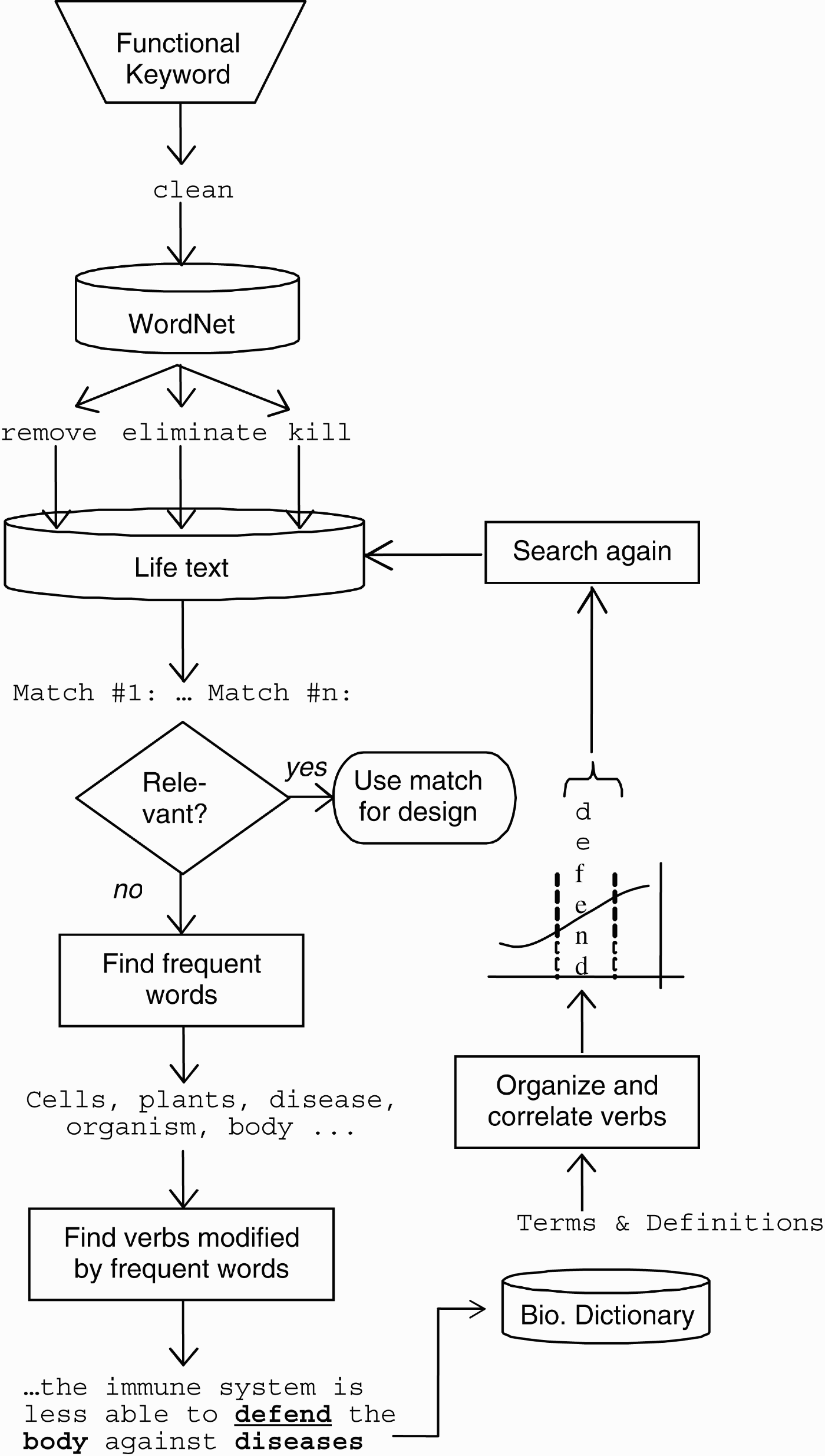
The method, based on word collocation and frequency analysis, is summarized in Figure 1 for the “clean/defend” example. First identified are hypernyms for clean in the lexical resource WordNet 3.0 (n.d.). A hypernym is a more general form of a word. For example, remove is a hypernym of clean. Related words are also identified from WordNet, such as hyponyms/troponyms of remove, for example, eliminate and kill. Next, these words are searched in the corpus of the Purves et al. (Reference Purves, Sadava, Orians and Heller2001) text. Matches with text excerpts containing these words are assessed for relevance to the problem using metrics that are described in Section 2.2.1.
A flow chart of the method bridging the keyword clean to defend. Adapted from “Bridging cross-domain terminology for biomimetic design,” by I. Chiu and L. Shu. Proc. ASME 2005 Int. Design Engineering Technical Conf. Computers and Information in Engineering Conf., Paper No. DETC2005/DTM-84908, Long Beach, CA, September 24–28, 2005. Copyright ASME 2005. Adapted with permission.
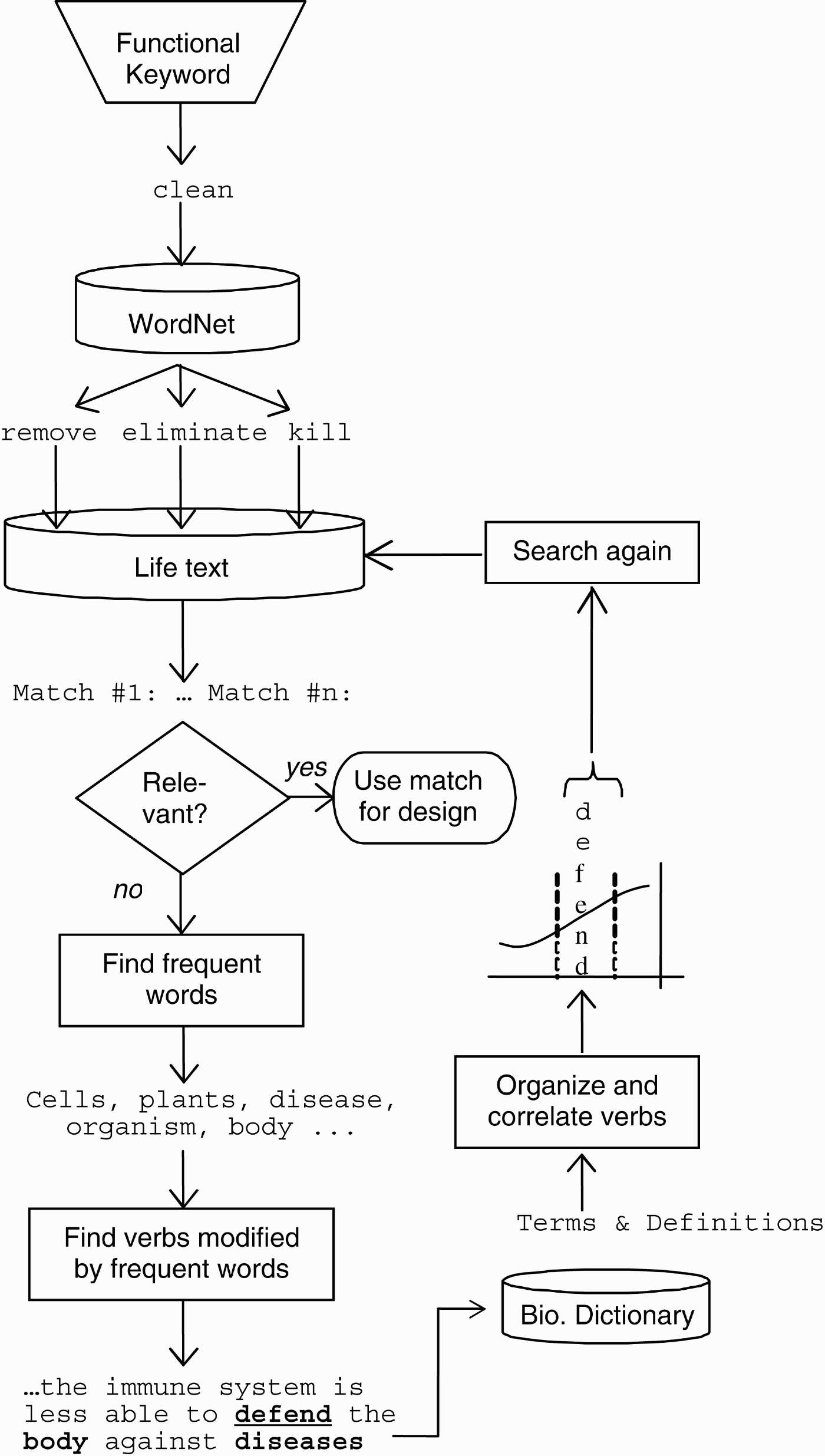
Words, usually nouns (e.g., cells and plants), that occur frequently in the relevant matches are then identified, as are the verbs that modify or act on them.
These verbs are then checked against both the defined terms as well as definition content of a biological dictionary. Verbs that are defined or part of a defined term are called “biologically significant.” “Abscise” means to naturally separate or fall off such as a dead leaf or ripe fruit, and it is an example of a biologically significant verb. Verbs that are not part of defined terms but appear in the definition of terms are called “biologically connotative.” “Defend” would be an example of a biologically connotative word, as it is used in the definitions of several defined terms, but is not a defined term itself. Together, biologically significant and connotative words are termed biologically meaningful. These biologically meaningful keywords are then ordered by frequency of occurrence in the biology dictionary. Most useful bridge words are found between certain frequency cutoffs. Those that occur too frequently tend to be too common in the English language, for example, forms of to be or to have. Those that occur very infrequently tend to be fairly obscure terms. Figure 1 schematically shows how “defend” is located within certain frequency cutoffs. This method was used to locate “defend” as well as other biologically meaningful keywords for the “clean” example. The bridging method also identified the following biologically meaningful keywords: “survive” for an example involving encapsulation, and “break” or “breakdown” for releasing microobjects (Chiu & Shu, Reference Chiu and Shu2007).
Another approach attempted for the bridging method was to simply collect all nonsearch verbs in the vicinity of the search verb. However, this method yielded far fewer useful, biologically meaningful words.
Biologically meaningful keywords for verbs of the functional basis
More recently, the bridging method was used to identify biologically meaningful keywords for verbs of the functional basis (Cheong et al., Reference Cheong, Shu, Stone and McAdams2008). The functional basis contains verb–object pairs that span the functionality of mechanical devices (Stone & Wood, 2001). Cheong et al. (Reference Cheong, Shu, Stone and McAdams2008) identified four categories, or cases, where most biologically meaningful keywords appear. Examples from the Purves et al. (Reference Purves, Sadava, Orians and Heller2001) corpus illustrate these cases below.
Case 1—synonymous pair: Many groups or pairs of words are used synonymously in the biological domain, often in the same phrase or sentence, for example, “convert” and “transduce” in “This information is received and converted, or transduced, by sensory cells into electric signals . . .”
Case 2—implicitly synonymous pair: These are cases where synonymous words are present, but in a separate phrase or sentence. These require a closer investigation of search results, and most such synonyms appear in this manner, for example, “conduct” and “transport” in “The xylem of tracheophytes conducts water from roots to aboveground plant parts. It contains conducting cells called tracheary elements, which undergo programmed cell death before they assume their function of transporting water and dissolved minerals.”
Case 3—biologically specific form: Biologically meaningful words can sometimes be a specific form of an engineering word, for example, “photosynthesize” from “convert” and “mutate” from “transform” in “Mutations of one of the homeotic genes, bithorax, transform the third thoracic segment into a second copy of the second thoracic segment.”
Case 4—mutually entailed pair: This is a symmetric relationship where one action is performed to enable another action, and the sequence of the two actions can be switched in the description with an appropriate prepositional phrase. An example is “absorb” and “break down” in “Humans absorb amino acids by breaking down proteins from food,” which can be restated as “Humans breakdown proteins from food to absorb amino acids.”
Cheong et al. (Reference Cheong, Shu, Stone and McAdams2008) applied the above method and cases to identify biologically meaningful keywords for all the verbs of the functional basis. Ke et al. (Reference Ke, Chiu, Wallace and Shu2010) incorporated the tagging of lexicographical data to each word of the corpus, which enables the automation of the above.
2.1.3. Categorization of search results
Along with the advantages, there are challenges involved with using natural-language knowledge sources to identify biological analogies. A primary difficulty involves the quantity and quality of matches.
Even with a single text used as the source, there can be an unmanageable number of matches. Identifying words that frequently collocate with sought keywords can be used to summarize dominant biological phenomena associated with keywords. For example, high-frequency words were “predator,” “prey,” and “species” for the keyword “eliminate,” describing how interactions between prey and predator species lead to one another's elimination (Chiu & Shu, Reference Chiu and Shu2004).
Ke et al. (Reference Ke, Wallace and Shu2009) also investigated using Wikipedia categories to categorize search results. Currently explored are other means for categorization so that search results can be more quickly skimmed, such as sorting by the subject acting out the keyword verb, and/or by the object that the keyword verb acts upon.
2.2. Evaluation, selection, and application of biological phenomena
After search words are generated and text-excerpt matches for them identified and presented, a human designer selects matches that appear most promising as possible design stimuli. However, evaluating the relevance of potential analogies is a less straightforward process than evaluating the relevance of matches to specific information sought. For example, in a search for “map of Toronto” it is far more obvious which matches actually contain the map sought. In contrast, when searching for a cross-domain analogy, where the actual physical entities are likely to be different between the source (i.e., biology) and target (i.e., engineering) domains, it is more complex to evaluate relevance, much less usefulness of a given match. This section describes challenges faced from the evaluation to the application of matches, and means toward overcoming these challenges.
2.2.1. Evaluation and selection of matches
Hacco and Shu (Reference Hacco and Shu2002) noted that matches, or text excerpts containing sought keywords, with the following characteristics can be eliminated right away.
1. Matches may contain the sought keyword in a different sense, or meaning. For example, when searching for biological analogies for “seal” as in sealing a joint, many matches contained “seal” as in the aquatic mammal. Clearly, these matches were irrelevant and therefore disregarded.
2. Matches may contain the sought keyword acting on abstract, rather than physical objects. For example, when searching for “balance” the matches regarding balancing flow may be more useful than those regarding balancing an equation. For mechanical design problems that involve physical objects, matches that contain abstract entities, for example, interest, equation, and theory, as the objects of search keywords are generally less applicable and therefore disregarded.
Ke et al. (Reference Ke, Chiu, Wallace and Shu2010) implemented the tagging of each word in a corpus with its part of speech, if it is a noun, whether it is an abstract or physical noun, possible senses, and other lexicographic data, toward automatic hiding of matches that are unlikely to be relevant.
Mak and Shu (Reference Mak and Shu2004a) found that descriptions of biological phenomena that contain principles and behaviors in addition to forms, or biological entities, were more useful as design stimuli. Furthermore, Cheong et al. (2009, Reference Cheong, Chiu and Shu2010) found that descriptions of biological phenomena that contain causal relationships are more likely to be useful analogies for design problems. In a causal relation, one action causes another action, and in our matches, explains how particular behaviors achieve certain functions in biology. For example, in “Lysozyme is an enzyme that protects the animals that produce it by destroying invading bacteria” (Purves et al., Reference Purves, Sadava, Orians and Heller2001), the “destroying” behavior enables the function of “protecting.”
2.2.2. Selection and application of matches
Another challenge in using biological analogies for design involves the human process of extracting relevant strategies from the biological phenomena and applying these strategies to design problems. This is not just a problem after relevant analogies are identified, but can affect the very selection of what is deemed relevant. Factors affecting perception of relevance are particularly applicable to our approach, as currently results are presented as a list of text excerpts that contain the sought keyword. For our studies described below, we selected descriptions of biological phenomena that have a functional connection to the given problem, and observed how students applied the phenomena to solve specified problems. Gentner (Reference Gentner1989) and Goel (Reference Goel1997) established foundations for analogical reasoning relevant to our work. More recently, Vattam et al. (Reference Vattam, Helms and Goel2008) develop a conceptual framework for compound analogical design.
Similarity types
In a study conducted by Mak and Shu (Reference Mak and Shu2004a), students were asked to develop concepts to enable “clean clothes” using the following excerpt from Purves et al. (Reference Purves, Sadava, Orians and Heller2001):
Barriers and local agents defend the body—skin is a primary innate defense against invasion. The bacteria and fungi that normally live and reproduce in great numbers on our body surfaces without causing disease are referred to as normal flora. These natural occupants of our bodies compete with pathogens for space and nutrients, so normal flora are a form of innate defense.
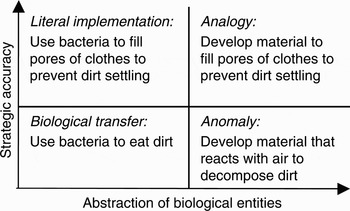
Mak and Shu (Reference Mak and Shu2004a) identify four similarity types observed between the biological phenomena presented and the concepts developed using them as stimuli as, literal implementation, biological transfer, analogy and anomaly, as shown with examples in Figure 2. Along the two axes of Figure 2 are strategic accuracy and abstraction of biological entities. The intended analogous solution accurately transfers the strategy from the biological phenomena to the concept without transferring the biological entities, which in this case include bacteria. A literal implementation transfers the biological entities, bacteria, as well as the strategy from the biological phenomena to the concept, whereas a biological transfer carries the biological entities, bacteria, into the solution without applying the strategy presented. Finally, an anomaly transfers neither the entities nor strategy from the biological phenomena to the solution. Some anomalous concepts result from misunderstanding of the biological phenomenon. Other such instances can be attributed to fixation on a few words in the text description without regard for the overall strategy or principle presented (Mak & Shu, Reference Mak and Shu2004b).
Types of similarities between biological phenomena and developed concepts. Reprinted from “Abstraction of biological analogies for design,” by T.W. Mak and L.H. Shu, 2004a, CIRP Annals 53(1), 117–120. Copyright CIRP 2004. Reprinted with permission.

Mapping tool
Two persisting difficulties observed in students using descriptions of biological phenomena were: inability to transfer information from biology to engineering, and fixation on specific phrases of the description. This prompted further studies where students were given outlines of strategies to be applied to both biological and engineering domains to aid analogical mapping (Mak & Shu, Reference Mak and Shu2008). Compared to earlier results, the quality of generated concepts improved. Although participants using the mapping tool were observed to extract strategies consistent with the biological phenomena presented, they persisted in applying strategies to specific attributes of the given problem. For example, participants were compelled to apply strategies to only one attribute of the problem domain, for example, “clothing” in the example problem, even though the resulting concepts were not necessarily feasible. Because concepts generated varied with attributes chosen, a possible way of reducing fixation and increasing the variety of solutions identified is to encourage one to list various attributes, for example, clothing, dirt, and detergent, of the problem and then generate ways in which the biological strategies can be applied to the list of attributes.
Further work by Cheong and Shu (Reference Cheong and Shu2009) and Cheong et al. (Reference Cheong, Chiu and Shu2010) suggests a template would be especially useful for descriptions of biological phenomena where a causal relationship must be recognized and transferred across domains.
Functional models
Vakili et al. (Reference Vakili, Chiu, Shu, McAdams and Stone2007) describe a preliminary study involving the role of functional models in the presentation of biological phenomena as stimuli. In this study, participants were asked to solve a microassembly problem given a set of biological representations, including functional models, of leaf abscission for inspiration. The visual aids presented to the designers were investigated, and the use of functional models of biological phenomena in particular was critiqued. The designs resulting from the study were classified and theories drawn as to possible influences of the biological representations. Observations, retrospective conversations with participants, and analogical reasoning classifications were used to determine positive qualities as well as areas for improvement in representation of the biological domain. Findings suggest that designers need an explicit list of all possible inherent biological strategies, extracted using function structures with objective graph grammar rules. Nagel et al. (Reference Nagel, Midha, Tinsley, Stone, McAdams and Shu2008) explored the use of functional models in biomimetic conceptual design.
3. EXAMPLES
Several analogies at various levels of biological organization were identified and applied to case studies in: design for remanufacture (Vakili & Shu, Reference Vakili and Shu2001; Hacco & Shu, Reference Hacco and Shu2002; Shu, Reference Shu2004), authorized disassembly (Saitou et al., Reference Saitou, Shalaby and Shu2007), microassembly (Shu et al., Reference Shu, Lenau, Hansen and Alting2003, Reference Shu, Hansen, Gegeckaite, Moon and Chan2006), sensing (Lenau et al., Reference Lenau, Cheong and Shu2008), redesign of fuel cells (Currie et al., Reference Currie, Fung, Mazza, Wallace and Shu2009; Ke et al., Reference Ke, Chiu, Wallace and Shu2010), protection during hobbies (Cheong et al., Reference Cheong, Shu, Stone and McAdams2008), and protection from lunar regolith (Davidson et al., Reference Davidson, Bligh, Maloney, McKnight, Young, Shu, Potvin and Warkentin2009).
Summarized below are three selected case studies executed in chronological order over the span of nearly a decade. Of interest is how the above results were applied to the case studies as they became available, enabling the elucidation of further insights and challenges.
3.1. Design for remanufacture
3.1.1. Introduction and problem definition
Remanufacture is a process applied to products at their end of life that seeks to reuse product components. Advantages over recycling for scrap material include conservation of resources required to melt and reform components. One design guideline identified to facilitate remanufacture is that product features that are prone to failure should be made separable (Shu & Flowers, Reference Shu and Flowers1999). In this way, the failed features can be replaced, enabling the reuse of a component without labor- and capital-intensive repair operations. However, making failure-prone parts separate increases part count and assembly cost. Biological analogies were sought to address this apparent contradiction between ease of assembly and ease of remanufacture.
3.1.2. Keyword and analogy identification
A search for the keyword remanufacture resulted in no matches in the biology text, which was no surprise. In this case, alternative keywords such as synonyms are required to find any matches. Other keywords used include synonyms and related words “repair” and “correct.” Matches identified using “repair” involve DNA repair mechanisms, including DNA proofreading during replication, mismatch repair, and excision repair. Excision repair was found to be the most analogous to repairs performed during remanufacture. Although the description of excision repair by Purves et al. (Reference Purves, Sadava, Orians and Heller2001) confirms relevance of the phenomenon to remanufacture, further research using a more advanced text, Friedberg et al. (Reference Friedberg, Walker and Siede1995), was required to determine details that could be used as stimuli for design (Vakili & Shu, Reference Vakili and Shu2001).
The search for the word “repair” also led to a match in Purves et al. (Reference Purves, Sadava, Orians and Heller2001) that provides an analogy at the organism level:
The defense systems of plants and animals differ. Animals generally repair tissues that have been infected. Plants, on the other hand, do not make repairs. Instead, they seal off and sacrifice the damaged tissue so that the rest of the plant does not become infected. This approach works because most plants, unlike most animals, can replace damaged parts by growing new stems, leaves, and roots.
The strategy extracted from the above is based on the ability of plants to add new parts to replace damaged ones, rather than expending resources in repairing damaged parts or sacrificing the entire organism. Applying this strategy to products involves planning for parts that can be used to replace a broken feature, without repairing the broken feature or replacing the entire part that contained the feature.
Another phenomenon identified using the keyword correct involves fainting. According to Purves et al. (Reference Purves, Sadava, Orians and Heller2001),
Blood must be returned from the veins to the heart so that circulation can continue. If the veins are above the level of the heart, gravity helps blood flow, but below the level of the heart, blood must be moved against the pull of gravity. If too much blood remains in the veins, then too little blood returns to the heart, and thus too little blood is pumped to the brain; a person may faint as a result. Fainting is self-correcting: A fainting person falls, thereby moving out of the position in which gravity caused blood to accumulate in the lower body.
The strategy derived from the above excerpt is that fainting is a form of defensive failure that prevents more serious failure.
3.1.3. Selected analogies and implementation
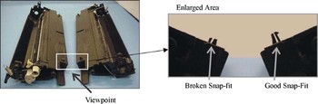
Snap fits embody a form of fastening often preferred for assembly and recycling purposes, but are problematic for remanufacture when they fail. Figure 3 compares failed and unbroken snap fits on toner-cartridges undergoing remanufacture.
Broken versus undamaged snap-fit features. Reprinted from Quantification and analysis of remanufacturing waste streams for improving product design, MS Thesis, by J. Williams, Reference Williams2001, University of Toronto, Department of Mechanical and Industrial Engineering. Copyright J. Williams Reference Williams2001. Reprinted with permission. [A color version of this figure can be viewed online at journals.cambridge.org/aie]

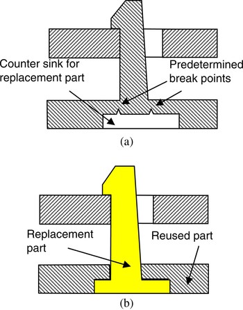
Applying the fainting strategy to the design of snap fits, Hacco and Shu (Reference Hacco and Shu2002) incorporated predetermined breakpoints into snap fit configurations as shown in Figure 4a that may cause earlier failure than with standard snap fit configurations, but the part containing the snap fit feature can be more easily reused. Applying the ability of plants to sacrifice and replace parts, a possible planned replacement part is shown in Figure 4b that can be used once the sacrificial feature in Figure 4a fails.
Redesigned snap fit to facilitate repair. (a) Snap fit redesigned with countersink and break points and (b) redesigned snap fit after failure and refurbishment. Reprinted from “Biomimetic concept generation applied to design for remanufacture,” by E. Hacco and L. Shu. Proc. ASME 2002 Int. Design Engineering Technical Conf. Computers and Information in Engineering Conf., Paper No. DETC2002/DTM-34177, Montreal, September 29–October 2, 2002. Copyright ASME 2002. Reprinted with permission. [A color version of this figure can be viewed online at journals.cambridge.org/aie]

3.1.4. Conclusions from remanufacture example
This was an explorative case study to confirm that keyword searches on natural language text can be used to identify relevant and novel analogies to solve engineering problems. Analogies were identified at several levels of biological organization, from the molecular to the ecosystem, with only two described in detail above. The abstraction of strategies from the biological phenomena is key to their realistic application, as opposed to literal implementation in engineering solutions.
3.2. Overcoming sticking in microassembly
3.2.1. Introduction
Collaboration with researchers with expertise in micro- and nanoengineering at the Technical University of Denmark led to the following case study in microassembly. Shu et al. (Reference Shu, Hansen, Gegeckaite, Moon and Chan2006) report the identification and use of biological analogies to solve the problem of sticking during microassembly. Selected release techniques based on DNA transcription and the abscission process in plants inspired concepts of new automated handling devices for microobjects.
3.2.2. Problem definition
A problem unique to microassembly is that size effects, which occur when part dimensions are scaled down, complicate the handling and assembly of micromechanical parts. At the microlevel, surface-related forces, such as electrostatic, van der Waals, and surface tension forces dominate gravitational forces. A common complication involves sticking between the gripping device and the micropart, which hinders the automation of picking and releasing operations. The goal then, is the controlled removal of a microobject from a gripping device.
3.2.3. Keyword and analogy identification
The functional keyword that can be derived from the above problem statement is “remove.” Chiu and Shu (Reference Chiu and Shu2004) had observed the value of using not just synonyms as alternative keywords, but also troponyms, or more specific manners of a functional verb. For example, “release” is a troponym, or more specific manner of the keyword remove. In addition to words lexically related to the functional keyword, Chiu and Shu (Reference Chiu and Shu2005, Reference Chiu and Shu2007) also developed a process to identify biologically meaningful keywords, that is, words that are relevant to the desired function in biology whose relationship may not be documented in lexical references such as dictionaries and thesauri. One such keyword for remove is “defend” because entities are sometimes removed in biological systems as a defensive mechanism.
DNA transcription
A match with “defend” identified the concept of regulated expression of interferons, which are proteins that defend against viral infections. The following phenomenon enables the regulated expression, or controlled production, of proteins.
In biology, transcription is the process of synthesizing RNA using one strand of DNA as the template. RNA is then used to synthesize proteins, for example, that can defend against viral infections. Discrete segments of the DNA (i.e., different genes) encode different proteins and these genes are transcribed and then translated into proteins. Because different proteins are synthesized as needed for specific purposes, the activities of several molecules (also proteins) determine whether the transcription process is carried out, and where along the DNA the transcription occurs.
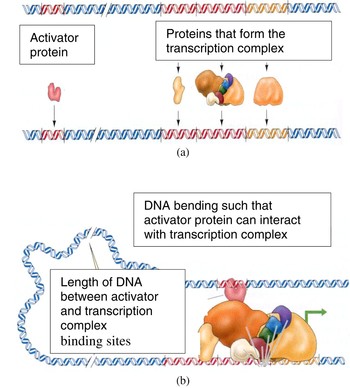
Figure 5a shows that the activator protein binds to a region of the DNA that is some distance away from where the proteins that form the transcription complex bind to the DNA. It is hypothesized that the DNA is bent such that the activator protein can contact the transcription complex, as shown in Figure 5b, to stimulate the transcription process (Purves et al., Reference Purves, Sadava, Orians and Heller2001). The specific binding of proteins involved is governed by their particular geometries and the molecular interactions between the proteins and the DNA.
(a) Proteins and binding regions on DNA and (b) the interaction of activator protein and transcription complex bound to different regions of DNA. Adapted from Life, the Science of Biology, 6th ed., by W.K. Purves, D. Sadava, G.H. Orians, and H.C. Heller, 2001. Sunderland, MA: Sinauer Associates. Copyright Sinauer Associates 2001. Adapted with permission. [A color version of this figure can be viewed online at journals.cambridge.org/aie]

The strategy extracted from the above biological phenomenon is as follows. Interactions due to specific geometries (or chemical characteristics) of entities as they move relative to each other determine whether proteins are synthesized in biology (to enable defense against, or removal of, invasive entities), and whether a microobject is released for our problem.
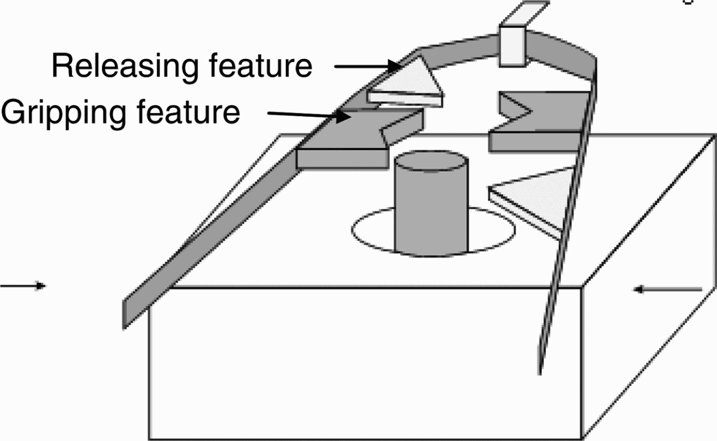
A possible physical realization of the above strategy is a ribbonlike structure with features that either grip or release microobjects based on the amount of surface area in contact with the microobject. A highly simplified schematic is shown in Figure 6. As the structure is rotated, features move relative to each other and the microobject. The geometry of the gripping features is such that sufficient contact with the object ensures a secure grip when the object is between these features. To release the object, the ribbon is rotated until the object is between the features that minimize contact. When the two sides of the ribbon are then pulled apart, the object will be released with minimal surface interactions.
Proposed microhandling tool inspired by DNA transcription. Reprinted from “Case study in biomimetic design: handling and assembly of microparts,” by L. Shu, H. Hansen, A. Gegeckaite, J. Moon, and C. Chan. Proc. ASME 2006 Int. Design Engineering Technical Conf. Computers and Information in Engineering Conf., Paper No. DETC2006/DTM-99398, Philadelphia, PA, September 10–13, 2006. Copyright ASME 2006. Reprinted with permission.
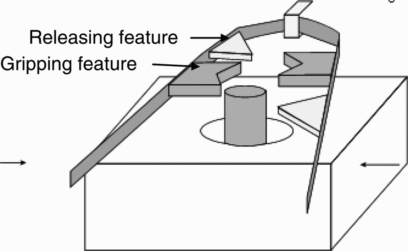
Analogical mapping between the source and target domains, guided by past work (Mak & Shu, Reference Mak and Shu2004b) is as follows. The strategy used for the controlled production of proteins that remove invasive entities in biology is transferred to the controlled release of microobjects. Chemical and geometric interactions between entities bound to different regions of DNA as portions of DNA move past each other is the mechanism behind the biological phenomenon. Physically, the DNA strand maps into the ribbon structure of the above concept, and the reactants map onto the geometric features attached to the ribbon structure. Geometric interactions between these features and the microobject are used to enable the release of the microobject by minimizing surface effects. Table 1 summarizes the mapping described above.
Analogical mapping for microobject release

Abscission
Multiple keywords, including defend, remove, and release located the phenomenon of abscission. This biological phenomenon was selected for further development and is detailed in the next section.
3.2.4. Selected analogy: Abscission
The previous phenomenon identified is the basis for how proteins are selectively synthesized to defend against infections, and led to a concept where features with different geometries would be used to maximize or minimize surface contact with the microobject as needed. However, this complex interaction mapped into a relatively complex solution compared to one that can be developed based on the abscission principle described below.
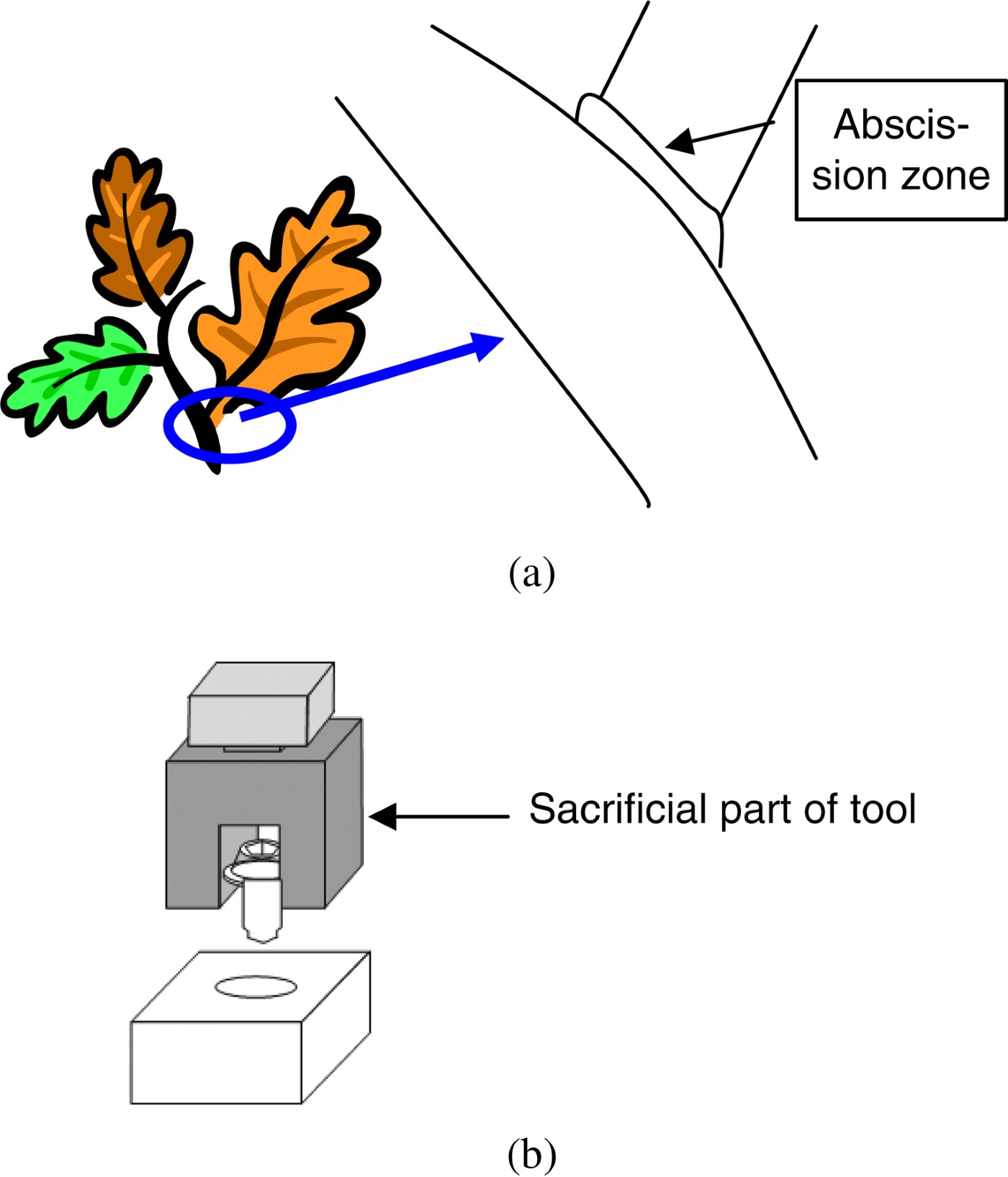
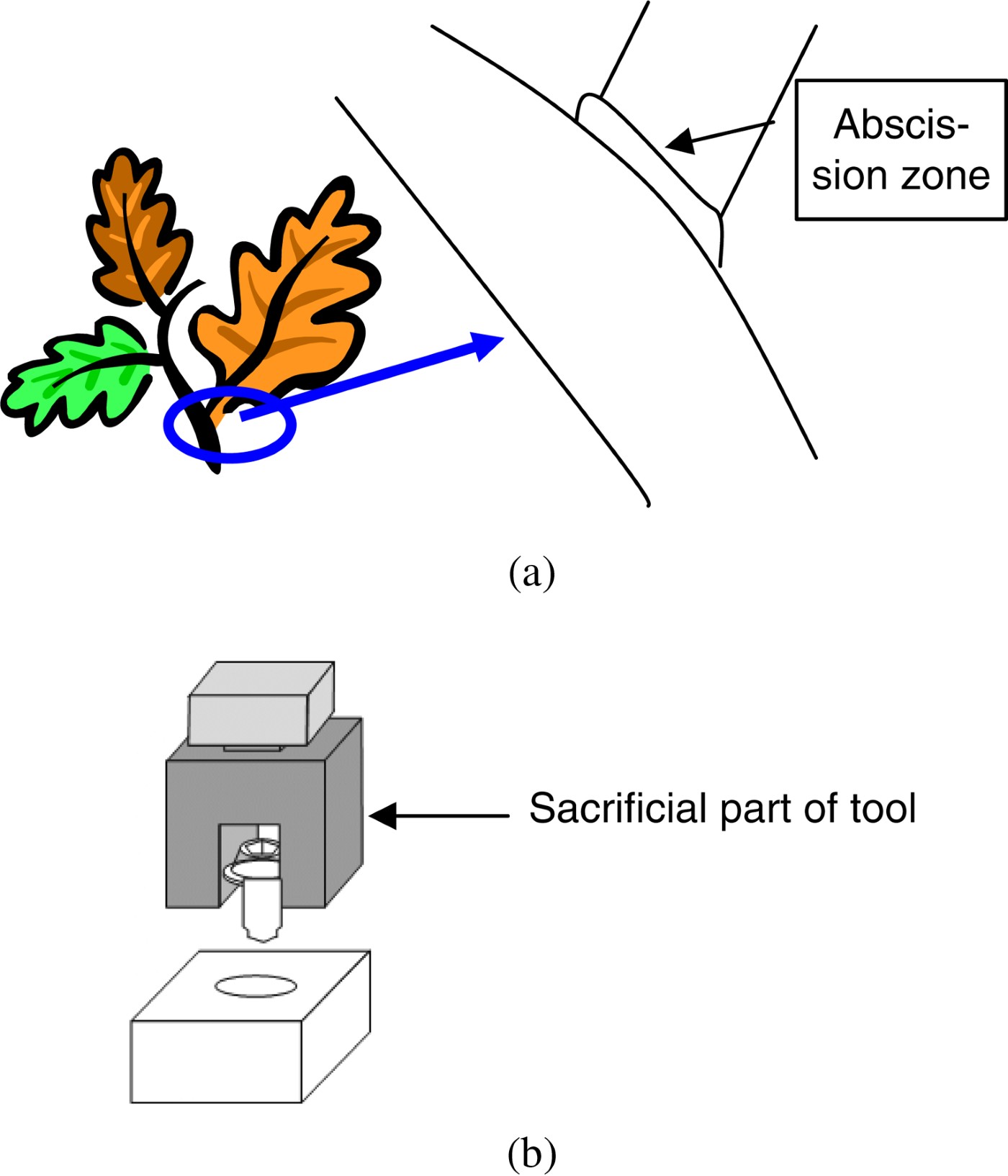
The phenomenon of abscission is the process by which leaves, petals, and fruits separate from a plant. Plants direct growth in different parts such as roots and shoots by strategically releasing a hormone called auxin. When leaves are damaged through infection, for example, or are no longer needed, as in the winter season, the leaves stop producing auxin, allowing the further expression of abscisic acid and ethylene, which advance abscission. As a result, specific parts of the stalks of the leaves break down and become completely detached from the plant. The base of some leaves contains a special layer of cells called the abscission zone (see Fig. 7a). In the absence of auxin, these cells swell and form a corklike material. This cuts off the flow of nutrients to the leaf and forms a seal between the leaf and the plant and protects the plant once the leaf separates (Purves et al., Reference Purves, Sadava, Orians and Heller2001).
(a) The abscission zone and (b) abscission applied to microassembly. Reprinted from “Case study in biomimetic design: handling and assembly of microparts,” by L. Shu, H. Hansen, A. Gegeckaite, J. Moon, and C. Chan. Proc. ASME 2006 Int. Design Engineering Technical Conf. Computers and Information in Engineering Conf., Paper No. DETC2006/DTM-99398, Philadelphia, PA, September 10–13, 2006. Copyright ASME 2006. Reprinted with permission. [A color version of this figure can be viewed online at journals.cambridge.org/aie]
3.2.5. Implementation
The abscission principle can be applied abstractly to microassembly as shown in Figure 7b. To overcome difficulties associated with the object adhering to the handling device, the object is released together with a part of the tool designated as sacrificial. The sacrificial part can be of significant mass to take advantage of gravity. In this way the object can be easily released. The sacrificial part of the tool can then either remain with the microobject or be subsequently removed.
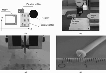
For the specific application of inserting a 0.6-mm metallic microscrew into a plastic counterpart, the abscission zone is physically implemented as a polypropylene rod of 4-mm diameter that is easily gripped and positioned by a small industrial robot with 6 degrees of freedom and a specified repeatability of ±0.02 mm (see Fig. 8).
(a) A top-view diagram of the experimental setup, (b) the experimental setup, (c) the gripper with a polypropylene rod over mounted screws, and (d) the polypropylene rod with a screw. Reprinted from “Case study in biomimetic design: handling and assembly of microparts,” by L. Shu, H. Hansen, A. Gegeckaite, J. Moon, and C. Chan. Proc. ASME 2006 Int. Design Engineering Technical Conf. Computers and Information in Engineering Conf., Paper No. DETC2006/DTM-99398, Philadelphia, PA, September 10–13, 2006. Copyright ASME 2006. Reprinted with permission.

The tip of the polypropylene rod is locally melted by heating, and then pressed over the head of the screw. The contact with the screw results in solidification of the polypropylene, and a solid bond between the rod and the screw is formed. The robot can now manipulate the screw into the plastic counterpart. Once the screw is tightened into its final position, the resulting increased torque will break the bond between screw and rod.
Other concepts considered for implementation of the abscission principle included the use of ice or other intermediate material that could be chemically dissolved. This, however, would introduce possible contaminants that are clearly undesirable. The abscission principle is more broadly interpreted as a physically weaker zone between the tree (gripper) and the leaf (screw). Gravitational, torsional, or other forces can be used to break this zone to separate the gripper and screw. In addition to relative “weakness,” another factor that led to the choice of a polymer as the intermediate-zone material is the ability of polymers to form the very small geometric features that mate with and thus handle the microscrew.
3.2.6. Conclusions from microassembly example
The added challenge of physical implementation of the biological strategy in a solution for this case study highlighted the following. Previous work (Shu et al., Reference Shu, Lenau, Hansen and Alting2003) conjectured that biological analogies at a scale comparable to the microassembly scale could be more directly implemented with less need for abstraction. However, the complex and tightly controlled biological processes identified closer to the microscale, only one of which was described for this case study, are difficult to emulate. The far simpler strategy of using an intermediate zone that could be broken down, thermally, chemically, or mechanically, was more easily implemented, although the concept of an abscission zone was abstracted into the form of polypropylene rods as opposed to being literally implemented.
This case study supports the importance of abstracting biological principles and entities to implement as practical engineering solutions, as it may not be possible or desirable to completely emulate analogous biological processes.
3.3. Protection from lunar regolith
3.3.1. Introduction
In lunar exploration, regolith, or dust, poses a significant problem due to its pervasiveness, adherence, and abrasiveness, causing premature failure of space suits and mechanisms. Davidson et al. (Reference Davidson, Bligh, Maloney, McKnight, Young, Shu, Potvin and Warkentin2009) report the use of biologically meaningful keywords to identify biological analogies to generate solutions for protection required during lunar exploration. Specifically, biomimetic concepts were developed to protect a light detection and ranging (LIDAR) device in a collaborative project between the Canadian Space Agency, Dalhousie University, and the University of Toronto.
3.3.2. Problem description
The challenge of protection from regolith is common to most scientific instruments used on the moon. Solutions must accommodate both the lunar environment and lunar regolith, which prevent implementation of most obvious solutions. Therefore, creative design techniques are required to expand the range of possible solutions and identify feasible ideas.
Lunar environment
Lunar temperatures vary from extremes of 120°C during the day to −150°C at night in the most common exploration areas. Solutions must accommodate large temperature swings that occur rapidly during the change from day to night and vice versa, which limits the selection and arrangement of materials.
The lunar atmosphere is sufficiently thin that it is to be considered as a hard vacuum. This affects material selection because materials, such as polymers, will outgas in a vacuum, causing severe physical degradation.
Lunar regolith
Lunar regolith adheres strongly to all surfaces. The mechanical aspect of adhesion is due to the jagged shape of regolith particles. In the absence of an atmosphere, there is no wind to round regolith particles, resulting in sharp edges. Most regolith particles are below 70 µm in diameter, and can infiltrate almost all mechanical systems, and even abrade mechanical seals.
Electrostatic adhesion is due to positive charging of particles by solar wind during the lunar day and negative charging by plasma electron currents at night. This electrostatic charging enables particles to cling to ungrounded conductive surfaces and nonconductive surfaces. Finer regolith grains will levitate under electrostatic charging, and therefore, dust is present at instrument level, even in the absence of any mechanical disturbance of regolith.
LIDAR device
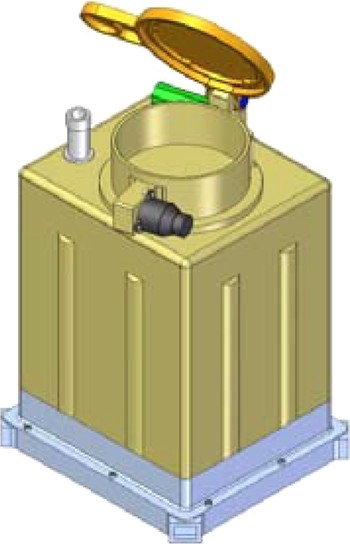
The LIDAR device of interest is similar to one used for the Phoenix Mission on Mars, shown in Figure 9. A LIDAR device is an optical instrument that can detect particle concentrations kilometers above the instrument itself and consists of two major components: a high-powered laser that points upward (small light grey cylinder) and an optical receiver (large gold cylinder). The closed cover protects both the laser beam canister and the receiver lens. Improved protection is required for the lens both during operation and while idle.
The LIDAR system (~20 cm height). Reprinted from “Biomimetic design of a multi-layered dust protection system for optical instruments operating in the lunar environment,” by M. Davidson, D. Bligh, N. Maloney, C. McKnight, W. Young, L.H. Shu, M.J. Potvin, and A. Warkentin. 6th Int. Conf. Innovation and Practices in Engineering Design and Engineering Education, Hamilton, Ontario, July 27–29, 2009. Copyright Canadian Design Engineering Network 2009. Reprinted with permission. [A color version of this figure can be viewed online at journals.cambridge.org/aie]

3.3.3. Keyword and analogy identification
The engineering keyword protect follows directly from the current problem statement. In the translation from engineering to biologically meaningful keywords, protect is grouped with the functional basis words prevent, inhibit, and shield. Corresponding biologically meaningful keywords are cover, surround, inhibit, destroy, change shape, bind, release, attach, protect, repel, push away, shield, and defend (Cheong et al., Reference Cheong, Shu, Stone and McAdams2008). More promising biologically meaningful keywords were selected. Those that led to matches described below are italicized above.
Matches for protect
The keyword protect returned several matches, most of which involve some physical protection/covering, for example, for embryos and seeds. One match was not used strictly analogously, but it did give an idea for a simple configuration of the lens cap that would result in less regolith falling onto the lens during opening. This matched phenomenon involved a “clam” and suggested a lens cap in the form of two halves of a bivalve that opens from the top, such that regolith that has collected on top is less likely to fall onto the lens than from a single hinged cap, the current configuration, shown in Figure 9.
Matches for repel
The keyword repel identified concepts that use coatings, for example, waxy coating on hair that repels water. One match, involving the use of like charges to repel versus opposite charges to attract, may be more conceptually novel than the use of coatings. This match led to the idea of using charge to manipulate regolith away from LIDAR parts.
Matches for destroy
Although destroy seems to be an antonym of protect, biological systems destroy entities to protect themselves. This is an example of a biologically meaningful keyword that may not be intuitively or lexically related to the engineering function. One match describes how proteins, once denatured, loose their structure and therefore behavior.
This strategy was linked to knowledge that because of specific lunar conditions and regolith composition, small amounts of microwave energy can be used to smooth out the rough surface of regolith so that it does not adhere as much.
In addition, the biologically meaningful keyword destroy identified a match describing how hemoglobin has a higher affinity to bind carbon monoxide, which destroys its ability to bind oxygen. The corresponding idea was to position foam around but not encapsulating parts to be protected, such that regolith binds to foam before reaching the lens or mechanism to be protected.
3.3.4. Selected analogies
Of the identified biological analogies, those selected for further investigation and development are detailed below. In addition, the feasibility of implementing strategies from a more obvious biological analogy, not identified as described above, is explored.
Bivalve class
Further investigation by Davidson et al. (Reference Davidson, Bligh, Maloney, McKnight, Young, Shu, Potvin and Warkentin2009) revealed that the bivalve class of mollusks, including scallops, clams, oysters, and mussels, have evolved for life in particulate-laden environments on earth, and protect themselves from both predation and environmental hazards, such as excessive particle intrusion, with their shells. The geometry of bivalve shells facilitates easy travel through sand and mud, while offering protection from hazards. The 10–20° angle where the two shell halves meet deflects sand away from mating surfaces, and the curvature of the shell itself sheds passing sand particles. The two halves of the bivalve pivot to open and close the shell using a flexible ligament, which is more resistant to particle fouling as it does not involve the rotational sliding motion typical of more standard mechanical hinges.
Charge
The strategy of using like versus unlike charges identified by the keyword repel led to the idea of moving and keeping particles around the perimeter of the LIDAR receiver using high-voltage direct current (DC) electromagnetic fields. This method enables active dust protection with the cover opened during operation, exploiting the electrostatic charge always present on lofted lunar dust that is not mechanically disturbed.
Human eye
Davidson et al. (Reference Davidson, Bligh, Maloney, McKnight, Young, Shu, Potvin and Warkentin2009) report that an obviously analogous biological phenomenon for the protection of a visual sensing system from dust is that of the human eye. Different types of tears hydrate the eye and provide a barrier between dust and the sensitive tissues of the eye. In addition, the eyelid provides a sweeping action to actively transport foreign particles to the perimeter of the eye's exposed surface. These particles are then collected at the inside edge of the eye where they are flushed from the eye with tears.
However, directly implementing many parts of the human eye analogy is ineffective for this problem. Use of fluids in the lunar environment is inappropriate because of the hard vacuum and large temperature ranges. The use of a mechanical wiper is unsuitable because of the abrasiveness of the particles and the sensitivity of the protected optical surfaces.
Transferable strategies include transporting particles to the perimeter of sensitive surfaces, and actively protecting these surfaces while in operation, as accomplished by the charge-inspired concept.
3.3.5. Implementation
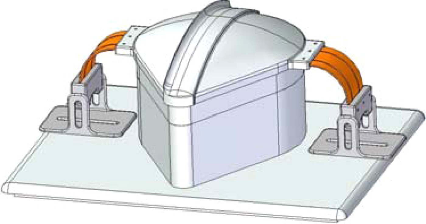
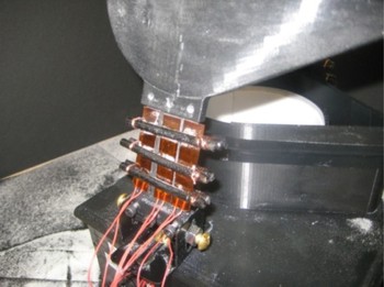
A prototype dust protection system developed based on the above analogies and concepts comprises two protection mechanisms: a shape memory alloy (SMA) actuated, bivalve-inspired lid assembly that protects the LIDAR device when not in operation, and an integral DC field generator in a circular collar that protects the LIDAR device during operation. Figure 10 shows the prototype assembly in its closed position. Figure 11 shows the actuator in the open position.
The prototype assembly in the closed position. Reprinted from “Biomimetic design of a multi-layered dust protection system for optical instruments operating in the lunar environment,” by M. Davidson, D. Bligh, N. Maloney, C. McKnight, W. Young, L.H. Shu, M.J. Potvin, and A. Warkentin. 6th Int. Conf. Innovation and Practices in Engineering Design and Engineering Education, Hamilton, Ontario, July 27–29, 2009. Copyright Canadian Design Engineering Network 2009. Reprinted with permission. [A color version of this figure can be viewed online at journals.cambridge.org/aie]
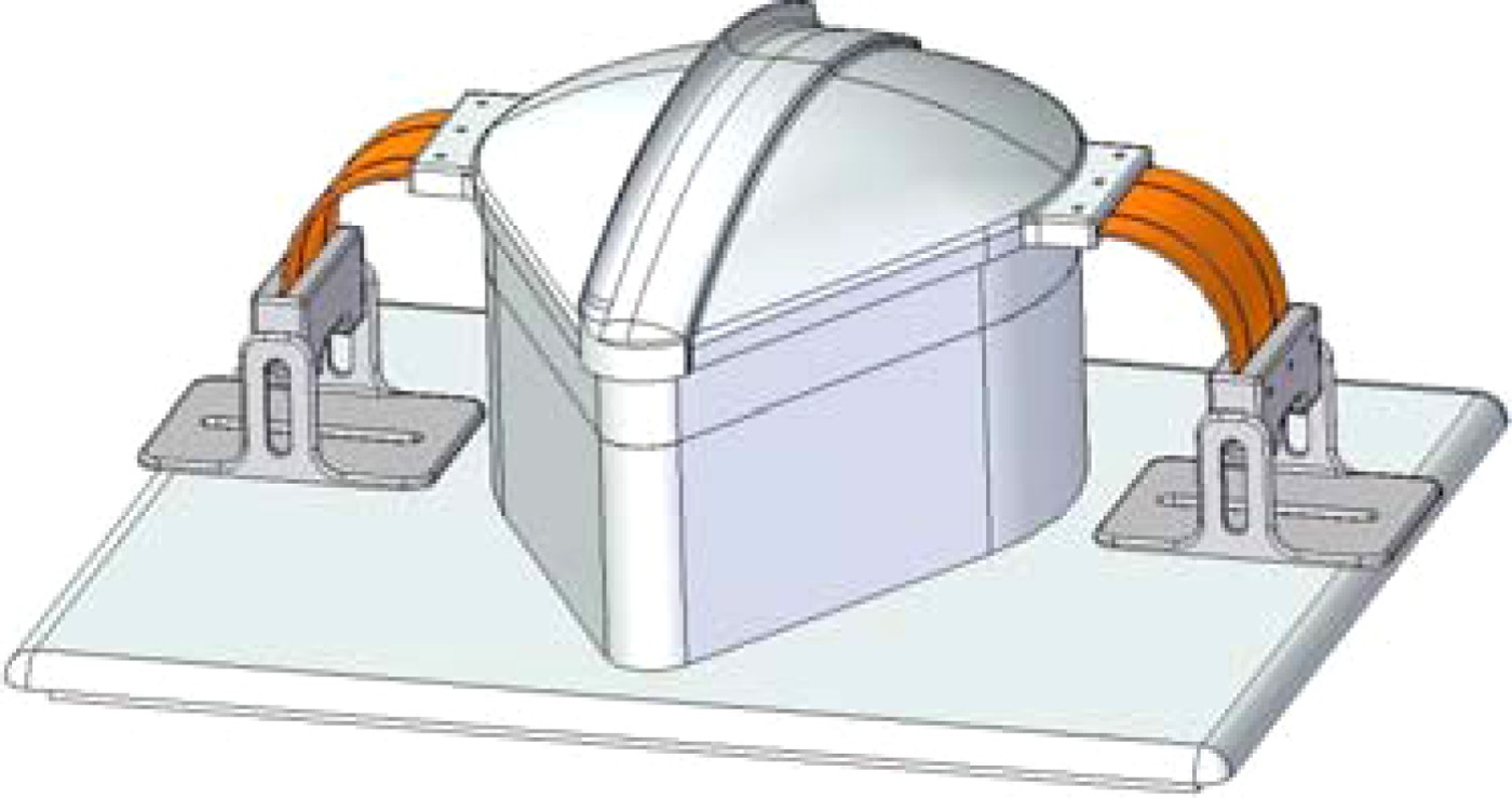
The actuator in the open position. Reprinted from “Biomimetic design of a multi-layered dust protection system for optical instruments operating in the lunar environment,” by M. Davidson, D. Bligh, N. Maloney, C. McKnight, W. Young, L.H. Shu, M.J. Potvin, and A. Warkentin. 6th Int. Conf. Innovation and Practices in Engineering Design and Engineering Education, Hamilton, Ontario, July 27–29, 2009. Copyright Canadian Design Engineering Network 2009. Reprinted with permission. [A color version of this figure can be viewed online at journals.cambridge.org/aie]

Bivalve-inspired lid assembly
Both the curvature and joint of the bivalve shell were incorporated into a two-piece cover system for the LIDAR device. The curvature of the lids facilitates the shedding of regolith and prevents regolith from falling onto the lens area during opening. The bivalve ligament joint led to development of an SMA hinge that also avoids the relative motion found in traditional rotating joints, increasing resistance to particle fouling.
Detailed implementation of the bivalve-inspired lid must meet the challenges introduced by the new lid configuration, specifically, the central seam between the two halves. An overlap protects the central seam where the two lid sections meet and prevents particles from falling straight down onto the LIDAR equipment upon opening. A pointed lip at the outside edge of the overlap section guides dust away from the edge of the lid while closed. To ensure alignment when closed, the underside edges of both lid sections have a mating groove that fits the top of the stationary base part that encases the LIDAR equipment. Thin-film surface heaters supply heat to SMA actuators, which move each of the two lid sections. Davidson et al. (Reference Davidson, Bligh, Maloney, McKnight, Young, Shu, Potvin and Warkentin2009) provide further details of this implementation.
Particle management using charge
The receiver section of the base contains two semicylindrical insulated aluminum sheets, which, oppositely charged, deflect charged particles away from the lens face. This solution works especially well in the lunar environment because of a weaker gravitational field compared to earth. A charged particle that enters the electric field is drawn toward the oppositely charged plate, and is held at that plate upon contact.
Prototype test results
Davidson et al. (Reference Davidson, Bligh, Maloney, McKnight, Young, Shu, Potvin and Warkentin2009) report that the SMA actuation system was able to achieve more than 100 repeatable lid opening and closing cycles, and the high-voltage DC field was able to control and deflect 98% of incoming charged polystyrene particles (mean diameter = 1 mm) away from a representative surface.
3.3.6. Conclusions from LIDAR protection example
This case study demonstrates a number of points in the implementation of biologically inspired design. First, obvious biological analogies that come to mind, for example, human eye protection, may have limited applicability to specific environments, for example, those on the moon. Second, biologically meaningful keywords, including those that are not obviously related to the engineering function (e.g., “destroy”) may lead to novel analogies and thus concepts. Although the clam analogy was not initially identified by a functional link, the clam operates in a particle-laden environment similar to the lunar environment. Therefore, the initial concept of two halves of a clamshell opening from the top was further improved with additional characteristics, for example, shell geometry and ligament joint, of the clam that enable it to better cope with such an environment. Third, configurations corresponding to biologically inspired concepts are likely to introduce novel challenges to be solved, for example, a central seam between two halves of a lid. These challenges may be appropriate for further creativity enhancing methods, including iterative use of biomimetic design.
4. SUMMARY AND CONCLUSIONS
This paper summarized our work over 10 years on developing a methodology to identify and use relevant biological analogies for any given engineering problem in a systematic manner. First introduced were challenges and measures toward addressing those challenges in natural-language analysis and analogical reasoning for using biological phenomena to develop engineering solutions. Biological analogies identified using the chosen approach for case studies in design for remanufacture, microassembly, and protection from lunar regolith, were then described to illustrate the process as it was further developed. Relevant biological analogies are presented as design stimuli, and as such, rely on appropriate designer application to produce the final designs.
The value of the natural-language approach is demonstrated by its ability to identify relevant analogies that may not be obvious. In some cases, such analogies outperform more obvious analogies. The main benefit of this approach is that analogies are not limited to those entered in advance into a database specifically for engineering design.
ACKNOWLEDGMENTS
The financial support of the Natural Sciences and Engineering Research Council of Canada as well as the National Science Foundation of the United States are gratefully acknowledged.
L.H. Shu is an Associate Professor in the Department of Mechanical and Industrial Engineering at the University of Toronto, where she holds the Wallace G. Chalmers Chair of Engineering Design. She obtained her PhD and SM from MIT and her BS from the University of Nevada, all in mechanical engineering. She has held research fellowships at the Technical University of Denmark, Allied Signal Aerospace Canada Inc., Eastman Kodak Company, the Naval Ocean Systems Center, and the Naval Training Systems Center. Dr. Shu is active in ASME and was Design Theory and Methodology Conference Program Chair in 2007, Conference Chair in 2008, and Technical Committee Chair in 2009. She is also a member of CIRP and received the F.W. Taylor Medal Award in 2004. Her research interests include creativity in conceptual design, systematic identification and application of biological analogies in biomimetic (biologically inspired) design, and identifying and overcoming obstacles to personal environmentally significant behavior.