Nomenclature
- Abbreviation
-
Description
- GA
-
genetic algorithm
- IAE
-
integral of absolute error
- ISE
-
integral of squared error
- ITAE
-
integral of time-weighted absolute error
- ITSE
-
integral of time-weighted squared error
- KF
-
Kalman filter
- LQR
-
linear quadratic regulator
- LQG
-
linear quadratic Gaussian
- MT
-
MATLAB tune
- MRAC
-
model reference adaptive control
- RL
-
root locus
- ZN
-
Ziegler–Nichols
Symbols
-
 $A{R_w}$
,
$A{R_{wt}}$
-
wing and tail aspect ratios
-
$b$
-
wingspan [m]
-
$c$
-
mean aerodynamic chord [m]
-
${C_{{D_0}}}$
,
${C_{{D_u}}}$
-
zero-lift drag, drag due to speed
-
${C_{D\alpha }}$
-
drag slope w.r.t. aoa [rad
${^{ - 1}}$
] -
${C_{L0}}$
,
${C_{Tu}}$
-
lift at zero AoA, thrust stability
-
${C_{L\alpha }}$
,
${C_{L\alpha w}}$
-
lift slope for wing [rad
${^{ - 1}}$
] -
${C_{L\alpha t}}$
,
${C_{L\alpha vt}}$
-
tail and vertical tail lift slopes [rad
${^{ - 1}}$
] -
${C_{m\alpha }}$
,
${C_{m{\alpha _q}}}$
-
pitch moment slope [rad
${^{ - 1}}$
] -
${C_{n\beta }}$
,
${C_{np}}$
,
${C_{nr}}$
-
yaw moment due to
$\beta $
, roll, yaw rate -
${C_{l\beta }}$
,
${C_{lp}}$
,
${C_{lr}}$
-
roll moment coefficients
-
${C_{Y{\delta _a}}}$
,
${C_{Y{\delta _r}}}$
-
sideforce coeff. due to aileron and rudder
-
${C_{n{\delta _a}}}$
,
${C_{n{\delta _r}}}$
-
yaw moment coeff. due to aileron and rudder
-
${C_{l{\delta _a}}}$
,
${C_{l{\delta _r}}}$
-
roll moment coeff. due to aileron and rudder
-
$d$
-
fuselage depth [mm]
-
${d_i}$
-
propeller diameter [in]
-
${D_{{\delta _e}}}$
,
${D_{{\delta _T}}}$
-
elevator deflection, throttle input [rad]
-
${I_{xx}}$
,
${I_{yy}}$
,
${I_{zz}}$
-
moments of inertia [kg
$ \cdot $
m
${^2}$
] -
${I_{xz}}$
-
product of inertia [kg
$ \cdot $
m
${^2}$
] -
${l_t}$
-
distance to tail quarter chord [m]
-
${L_v}$
,
${L_p}$
,
${L_r}$
,
${N_v}$
,
${N_p}$
,
${N_r}$
-
lateral moment derivs. [1/(m
$ \cdot $
s)] -
$m$
-
mass [kg]
-
${M_q}$
-
pitching moment due to
$q$
[1/s] -
${M_u}$
,
${M_{}}$
-
pitch moment derivs. [1/(m
$ \cdot $
s)] -
${M_{{\delta _e}}}$
,
${M_{{\delta _T}}}$
-
pitch moment due to elevator/throttle [1/s
${^2}$
] -
$p$
,
$q$
,
$r$
-
roll, pitch, yaw rates [rad/s] pitch propeller pitch [in]
-
$Q$
-
dynamic pressure at 60 km/h [N/m
${^2}$
] - rpm
-
propeller speed [1/min]
-
$S$
,
${S_r}$
-
wing and reference area [m
${^2}$
] -
${S_t}$
,
${S_{vt}}$
-
horizontal and vertical tail areas [m
${^2}$
] -
$u$
,
$v$
,
$w$
-
linear velocities in body frame [m/s]
-
${u_0}$
-
trim airspeed [m/s]
-
${V_H}$
-
horizontal tail volume ratio [-]
-
${x_{ac}}/c$
-
aerodynamic centre location
-
${x_b}$
,
${y_b}$
,
${z_b}$
-
UAV body coordinates [m]
-
${x_{cg}}/c$
-
centre of gravity location
-
${X_u}$
,
${X_w}$
,
${Z_u}$
,
${Z_w}$
-
force derivatives [1/s]
-
${X_{{\delta _e}}}$
,
${X_{{\delta _T}}}$
,
${Z_{{\delta _e}}}$
,
${Z_{{\delta _T}}}$
-
force derivs. of elevator and throttle [1/s
${^2}$
] -
${y_1}$
,
${y_2}$
-
aileron section endpoints [m]
-
${Y_v}$
,
${Y_p}$
-
lateral force derivatives [1/s]
-
${z_t}$
-
thrust offset along
$z$
-axis [mm] -
${z_{vt}}$
-
vertical tail height offset [mm]
-
${z_w}$
-
interval parallel to the z-axis from 1/4 chord to the fuselage centerline (mm)
-
$\eta $
,
${\eta _{vt}}$
-
horizontal-vertical tail efficiency
-
$\phi $
,
$\theta $
,
$\psi $
-
Euler angles (roll, pitch, yaw) [rad]
-
${\tau _a}$
,
${\tau _e}$
,
${\tau _r}$
-
control surface effectiveness
-
${\rm{\Lambda }}$
-
wing taper ratio
-
${{\rm{\Lambda }}_{c/4w}}$
-
quarter-chord sweep [rad]


1.0 Introduction
Unmanned aerial vehicles (UAVs) have become essential instruments in a variety of domains, from environmental monitoring and precision agriculture to military reconnaissance and security operations. UAVs have led to critical studies on improving stability and control mechanisms in different dynamic environments. As UAVs are required to fly under various wind conditions, it is essential to have rapid manoeuvres, and UAV systems must be able to perform under unpredictable external disturbances. To achieve this, robust flight control systems are crucial for optimal performance and reliability.
Recently, UAV applications have come to the forefront across various fields, especially defence, observation, exploration and inspection. Thanks to technological advances in aviation, low-altitude controlled systems are now being used to obtain earth images using UAV systems [Reference Swain, Jayasuriya and Salokhe1]. According to the Massachusetts Institute of Technology, UAVs for agricultural and environmental use are among ten technologies that can make a breakthrough [Reference Marinello, Pezzuolo, Chiumenti and Sartori2].
The creation of control architectures that maintain a stable and robust system in the face of intrinsic nonlinearity, model uncertainty and unforeseen disruptions is crucial to achieving advanced autonomy for fixed-wing UAVs.
Recent literature in the last five years about UAV control systems has focused on the convergence of optimal strategies, highlighting time-stability and constraint management. Robust design criteria are significantly enhanced through the widespread use of finite-time disturbance observers. In a study of Nguyen et al. the multivariable disturbance observer-based finite-time sliding mode attitude control (MDOB-FT-SM-AC) was proposed for matched and mismatched disturbances [Reference Nguyen, Oh, Moon and Kim3]. Similarly, in a previous study of the researchers, the finite-time disturbance observer-based modified super-twisting algorithm (FDO-STA) offers a robust path following against severe wind gusts [Reference Nguyen, Oh, Kim, Moon, Yang and Chen4], while fixed-time observers combined with sliding mode control guarantee unconditional convergence speed irrespective of initial conditions [Reference Cui, Zhou, Huang and Yang5]. To improve performance, optimisation with new learning methods, illustrated by adaptive dynamic programming (ADP) combined with adaptive sliding mode control (SMC), was proposed. The ADP method obtains optimal control for changing and uncertain conditions [Reference Zhang, Zhang and Dong6], In another study, radial basis function (RBF) neural networks were used for disturbance rejection for path following [Reference Zhao, Guo, Yan, Chang and Chen7].
There are numerous research methodologies and approaches for autonomous control of UAVs, such as fuzzy control [Reference Babaei, Mortazavi and Moradi8, Reference Doitsidis, Valavanis, Tsourveloudis and Kontitsis9], artificial neural networks [Reference Alsaade, Jahanshahi, Yao, Al-zahrani and Alzahrani10], adaptive control [Reference Andrievsky and Fradkov11, Reference Wu and Huang12], genetic algorithms (GA) [Reference Cordón, Herrera, Gomide, Hoffmann and Magdalena13, Reference Apriaskar, Prastiyanto and Utomo14] and Lyapunov theory. Kurnaz et al. [Reference Kurnaz, Cetin and Kaynak15] proposed an artificial neuro-fuzzy inference system (ANFIS) based on an autonomous flight control structure for a UAV. Abdulrahim and Lind [Reference Abdulrahim and Lind16] studied the shape-changing wing structure and control inspired by nature for UAVs, known as micro air vehicles. In a study on aircraft aerodynamics, Atkinson and Ferguson [Reference Atkinson and Ferguson17] used computational fluid dynamics for the combat UAV and compared it with experimental results. Casas et al. [Reference Casas, Malik, Delmelle, Karwan and Batta18] worked on creating a network with nodes and links to map the anatomy of enemy terrain to create a route for the UAV. Grabowski et al. [Reference Goetzendorf-Grabowski, Frydrychewicz, Goraj and Suchodolski19] designed a UAV, the PW-103, which can fly for long periods at medium altitudes. In a simulative study for trajectory planning, Jung et al. [Reference Jung, Ratti and Tsiotras20] achieved a real-time online implementation with an autopilot for trajectory planning and control in the simulation domain with high accuracy. In their research for crop protection, Psirofonia et al. [Reference Psirofonia, Samaritakis, Eliopoulos and Potamitis21] recommended using UAVs to detect diseases in olive trees. Öner et al. [Reference Öner, Çetinsoy, Sirimoğlu and Hançer22] presented a mathematical model for their proposed rotary wing UAV. Studies have reported that high-resolution systems and imaging and mapping tools in precision agriculture can perform an ideal task [Reference Hunt, Cavigelli, Daughtry, Mcmurtrey and Walthall23]. An event-triggered neural adaptive fixed-time control was developed for input saturation of multi-agent system and communication overhead was reduced in Liu et al. [Reference Liu and Yang24]. Aerial photography was used to obtain a crop yield map, and it was stated that remotely controlled systems are valuable in precision agriculture. In another study [Reference Lelong, Burger, Jubelin, Roux, Labbé and Baret25] in which UAV was used for quantitatively monitoring wheat products, 10 types of wheat were imaged by taking images with spectral-filtered cameras. Also, global positioning system (GPS) and camera images were used to combat insects and protect crops using UAVs in agriculture [Reference Lan, Thomson, Huang, Hoffmann and Zhang26]. Rasmussen et al. [Reference Rasmussen, Nielsen, Garcia-Ruiz, Christensen and Streibig27] aimed to create an image of weeds in barley with UAVs and aimed to increase crop productivity by using the UAV camera photos. The LQR controller weights for quadrotor-type UAV navigation points control were implemented by Ata et al. [Reference Ata and Gencal28] The efficacy of the optimisation strategies was demonstrated using the GA and particle swarm optimisation (PSO). Okasha et al. [Reference Okasha, Kralev and Islam29] compared PID, LQR and model predictive controllers (MPC) on the Parrot Mambo mini-drone to reveal the advantages and disadvantages of each control strategy. Similarly, MPC-based control achieved successful results for dual-thrust UAV to achieve manoeuvres in another work [Reference Mohammadi, Tayefi and Zhu30]. Apriaskar et al. [Reference Apriaskar, Prastiyanto and Utomo14] developed a GA-assisted LQR control for balancing a bicopter system with two propellers. The optimisation process was used to balance the system’s dynamics most appropriately. In Jiao et al. [Reference Jiao, Wang, Chen, Lu, Zou and Yang31], full-state attitude control is achieved in finite time using nonlinear transformation functions under full-state constraints and input saturations for fixed-wing UAVs.
Managing the complicated nonlinear dynamics and severe physical constraints that come with six degrees of freedom (DOF), flying is the focus of an ongoing research effort. In order to provide quick and precise setpoint tracking, this requires applying new nonlinear optimal control, such as a stabilising
 ${{\mathcal H}_\infty }$
feedback controller generated via approximation linearisation [Reference Rigatos, Gao, Busawon, Abbaszadeh, Siano, Al Numay and Zouari32]. Finite-time control techniques that use nonlinear transformation functions to obey full-state constraints and input saturation in the attitude system strictly preserve constraint adherence [Reference Jiao, Wang, Chen, Lu, Zou and Yang31]. In another study, fixed-time prescribed performance functions, which impose constraints on airspeed and altitude tracking errors through the path, have been applied in the backstepping method for longitudinal motion [Reference Tan and Guo33]. Aslan et al. [Reference Aslan and Yalçn34] noted that the immersion and invariance method for globally stable, non-chattering Euler angle control improves lateral control accuracy. Also, specific tasks, such as terrain following, require the implementation of control barrier functions (CBF) embedded in quadratic programming (QP) to set critical attitude limitations [Reference Kang and Kim35].
Lastly, tremendous progress has been made in both collaborative control and autonomy. The model compensation control (MCC) technique effectively decouples longitudinal and lateral channels and restrains disturbances in high-complexity systems by using a compensation function observer (CFO) [Reference Xu and Qi36]. Nonlinear model predictive control (NMPC) is essential for multiple-UAV image-based visual servoing [Reference Yang, Shi and Zhong37] and for optimising guidance rule parameters in planar curved path tracking [Reference Chen, Zeng, Wang and Wu38] in cooperative flight. Strict velocity constraints are satisfied by distributed protocols like distributed SMC [Reference Wang, Yu and Li39], and structural modifications like the use of multiple segmented ailerons with MPC greatly improve disturbance rejection in lateral roll control [Reference Sattar, Wang, Ansari, Hoshu and Khan40]. Yang et al. [Reference Yang, Shi and Zhong37] guaranteed the practical finite-time formation tracking despite ambient wind by using robust adaptive protocols.
This study explores different control methodologies applied to the Cessna-182 UAV’s longitudinal and lateral dynamics, emphasising their effectiveness in handling uncertainties and disturbances. By combining classical and modern control techniques, including PID tuning, LQR and LQG control, this paper aims to highlight the strengths and limitations of all controllers. The findings contribute to developing high-performance UAV control systems that ensure precision, stability and adaptability in various operational scenarios. The following parts give the dynamic equations of the Cessna-182 in Section 2. The proposed control system is provided in Section 3, and simulation results are evaluated in Section 4. In the end, conclusion is given in Section 5.
2. Mathematical model of the Cessna-182 UAV
This section includes the equations of motion (EoM), kinematic parameters, aerodynamic findings and wing profile equations of the Cessna-182. A structure with six DOF was obtained by deriving the force and moment EoMs according to the longitudinal and lateral axes of the aircraft.
As seen in Fig. 1, the aircraft performs a roll (
 $\phi $
) motion around the longitudinal axis X and a pitch (
 $\theta $
) motion around the lateral axis Y. Yaw movement (
 $\psi $
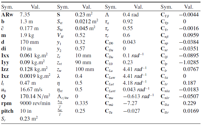
) occurs around the vertical axis of the aircraft, which indicates the left and right movement of the aircraft. The thrust force is generated along the X-axis by the action of the aircraft engine and contributes to the push of the aircraft, while the drag effect slows the aircraft down. The aircraft can lift and elevate along the Z axis by airflow to the wings and body. All aerodynamic and kinematic parameters of the Cessna-182 are given in Table 1.
The model has a 1.3 m wingspan and gross weight of 1.9 kg as a fixed-wing model. The force and moment equations for the UAV and the angular velocities
 $\left( {{\textrm{p}},{\textrm{q}},{\textrm{r}}} \right)$
, the Euler rates (
 $\dot \theta $
,
 $\dot \phi $
,
 $\dot \psi $
) are given in detail in the paper of Ulus et al. [Reference Ulus and Eski42]. All the stability derivative formulations used in the EoMs are given in Ulus and Eski [Reference Ulus and Eski42] and are therefore not repeated here.
Cessna-182 UAV parameters

Forces and moments of the aircraft [Reference Vogeltanz41].

2.1 Aerodynamic forces and moments
Aerodynamic forces and moments include the motion and interaction of the aircraft and airflow relative to the ground. Control inputs are the aircraft’s control surfaces, such as the aileron, rudder and elevator. Figure 2 shows the aerodynamic control surfaces on the aircraft. The displacement of the control surfaces generates lift and drag.
Aerodynamic control surfaces.

Aerodynamic forces in the centre of the aircraft also cause aerodynamic moments. A change in the elevator surface causes a pitching moment change. Figure 3 defines the pitching moment in the wind axis with lift and drag forces.
Lift, drag force and pitching moment.

While longitudinal motions occur according to the vertical axis of symmetry, lateral motions happen in the form of lateral force, roll moments or yaw moments resulting from the asymmetric air flow of the aircraft. These interactions may arise from lateral wind or rudder control surfaces.
Equations (1–6) define the parameters for longitudinal and lateral motions and their functional dependencies. In these equations,
 ${{\textrm{C}}_L}$
,
 ${{\textrm{C}}_D}$
,
 ${{\textrm{C}}_m}$
are the dimensionless aerodynamic coefficients,
 ${\textrm{S}}$
is the platform area of the wing surface,
 ${\textrm{c}}$
is the mean aerodynamic cord,
 ${\textrm{b}}$
is the span of the wing,
 $\rho $
is aerodynamic pressure and
 ${{\textrm{V}}_a}$
is airspeed.
 ${{\textrm{F}}_{lift}}$
,
 ${{\textrm{F}}_{drag}}$
,
 ${{\textrm{F}}_{lat}}$
represent the forces acting on the aircraft’s
 ${\textrm{x}},{\textrm{y}},{\rm{z}}$
axis, while
 ${\rm{L}}$
,
 ${\rm{M}}$
,
 ${\rm{N}}$
stand for the roll, pitch, yaw moments, respectively.
 \begin{align*}\begin{array}{*{20}{l}}{{\textrm{Longitudinal\,plane}}}\end{array}\end{align*}
 \begin{align}{F_{lift}} = \frac{1}{2}\rho .V_a^2.S\left( {{C_L}_0 + {C_L}_\alpha {\rm{\;}}.\alpha + {C_L}_q{\rm{\;}}.\frac{c}{{2{V_a}}}{\rm{\;}}.q + {C_L}_{{\delta _e}}{\rm{\;}}.{\delta _e}} \right)\end{align}
 \begin{align}{F_{drag}} = \frac{1}{2}\rho .V_a^2.S\left( {{C_D}_0 + {C_D}_\alpha .\alpha + {C_D}_q.\frac{c}{{2{V_a}}}.q + {C_D}_{{\delta _e}}.{\delta _e}} \right)\end{align}
 \begin{align}M = \frac{1}{2}\rho .V_a^2.S.c\left( {{C_M}_0 + {C_M}_\alpha .\alpha + {C_M}_q.\frac{c}{{2{V_a}}}.q + {C_M}_{{\delta _e}}.{\delta _e}} \right)\end{align}
 \begin{align*}\begin{array}{*{20}{l}}{{\textrm{Lateral\,plane}}}\\{}\end{array}\end{align*}
 \begin{align}{F_{lat}} = \frac{1}{2}\rho .V_a^2.S\left( {{C_Y}_0 + {C_Y}_\beta {\rm{\;}}.\beta + {C_Y}_p{\rm{\;}}.\frac{b}{{2{V_a}}}{\rm{\;}}.p + {C_Y}_r{\rm{\;}}.\frac{b}{{2{V_a}}}{\rm{\;}}.r + {C_Y}_{{\delta _r}}{\rm{\;}}.{\delta _r} + {C_Y}_{{\delta _{}}}{\rm{\;}}.{\delta _a}} \right)\end{align}
 \begin{align}L = \frac{1}{2}\rho .V_a^2.S.b\left( {{C_l}_0 + {C_l}_\beta {\rm{\;}}.\beta + {C_l}_p{\rm{\;}}.\frac{b}{{2{V_a}}}{\rm{\;}}.p + {C_l}_r{\rm{\;}}.\frac{b}{{2{V_a}}}{\rm{\;}}.r + {C_l}_{{\delta _r}}{\rm{\;}}.{\delta _r} + {C_l}_{{\delta _a}}{\rm{\;}}.{\delta _a}} \right)\end{align}
 \begin{align}N = \frac{1}{2}\rho .V_a^2.S.b\left( {{C_n}_0 + {C_n}_\beta {\rm{\;}}.\beta + {C_n}_p{\rm{\;}}.\frac{b}{{2{V_a}}}{\rm{\;}}.p + {C_n}_r{\rm{\;}}.\frac{b}{{2{V_a}}}{\rm{\;}}.r + {C_n}_{{\delta _r}}{\rm{\;}}.{\delta _r} + {C_n}_{{\delta _a}}{\rm{\;}}.{\delta _a}} \right)\end{align}
 $\alpha $
,
 $\beta $
,
 ${\rm{p}}$
,
 ${\rm{q}}$
and
 ${\rm{r}}$
in Equations (1–6) are angle-of-attack, sideslip angle, roll rate, pitch rate and yaw rate, respectively.
 ${\delta _{\rm{a}}}$
,
 ${\delta _{\rm{e}}}$
and
 ${\delta _{\rm{r}}}$
are defined as control derivatives for aileron, elevator and rudder control surfaces. In the Appendix section, Table A1 shows the values of some geometrical and aerodynamic parameters of the test model Cessna-182 aircraft.
The fixed-wing UAV model must be able to maintain a horizontal position and constant altitude during a certain flight speed. The UAV model must provide combinations such as angle-of-attack (
 $\alpha $
), thrust adjustment and angular changes of aileron, elevator and rudder required at
 ${V_{T0}}$
flight speed. These values are referred to as the trim (equilibrium) conditions of flight and the stabilised conditions of motion, which are given in Equation (7).
 \begin{align}\begin{array}{*{20}{l}}{{U_0} = {V_{T0}}. \cos {\alpha _0},{W_0} = {V_{T0}}.\sin {\alpha _0},{Q_0} = 0,{\theta _0} = {\alpha _0},} {}{}\\{{V_0} = {P_0} = {R_0} = {\phi _0} = {\psi _0} = 0.} {}{}\end{array}\end{align}
The longitudinal EoMs are
 \begin{align}\begin{array}{*{20}{l}}{{F_x}} {}{ = m{\rm{\;}}\dot U = - m.g.\sin \alpha + q.S.\left( {{C_L}.\sin \alpha - {C_D}.\cos \alpha } \right) + T,}\\[3pt]{{F_z}} {}{ = m{\rm{\;}}\dot W = m.g.\cos \alpha + q.S.\left( {{C_L}.\cos \alpha + {C_D}.\sin \alpha } \right),}\\[3pt]M {}{ = \dot Q{\rm{\;}}{I_y} = q.S{\rm{\;}}.c{\rm{\;}}.{C_M} + T{\rm{\;}}.{e_T} + q.S\left( {{C_L}.\sin \alpha - {C_D}.\cos \alpha } \right).{h_0}.}\end{array}\end{align}
T is the thrust force and
 ${e_T}$
is the thrust line offset. The distance from the aerodynamic centre to the centre of gravity can be expressed as
 ${h_0}$
.
 \begin{align}{C_L} = {C_{L0}} + {C_L}_\alpha {\rm{\;}}.\alpha + {C_L}_q{\rm{\;}}.\frac{c}{{2{V_a}}}{\rm{\;}}.q + {C_L}_{{\delta _e}}{\rm{\;}}.{{\rm{\delta }}_e},\end{align}
 \begin{align}{C_D} = {C_0} + {C_D}_\alpha {\rm{\;}}.\alpha + {C_D}_q{\rm{\;}}.\frac{c}{{2{V_a}}}{\rm{\;}}.q + {C_D}_{{\delta _e}}{\rm{\;}}.{\delta _e},\end{align}
 \begin{align}{C_M} = {C_{M0}} + {C_M}_\alpha {\rm{\;}}.\alpha + {C_M}_q{\rm{\;}}.\frac{c}{{2{V_a}}}{\rm{\;}}.q + {C_M}_{{\delta _e}}{\rm{\;}}.{\delta _e}\end{align}
The control surface parameters and graphs are below for the moment balance on the aircraft axes at a
 ${V_{T0}}$
= 60 km/h flight speed. These results were obtained using the “fminsearch” optimisation algorithm in MATLAB, and the results are shown below and in Fig. 4:

Equilibrium states (u, v, w, p, q, r,
 $\phi ,\theta ,\psi $
) of the Cessna182.

2.2 The longitudinal equations of the Cessna-182 UAV
If the linearised longitudinal parameters previously mentioned in Equations (1–6) are considered and expressed in the state-space matrix, Equation (12) is obtained. State-space for both longitudinal and lateral motion details for parameter explanations can be seen in Refs (Reference Ulus and Eski42, Reference Oktay, Konar, Onay, Aydin and Mohamed43):
 \begin{align}\left\{ {\begin{array}{*{20}{l}}{{\rm{\Delta }}\dot u}\\[2pt]{{\rm{\Delta }}\dot w}\\[2pt]{{\rm{\Delta }}\dot q}\\[2pt]{{\rm{\Delta }}\dot \theta }\\[2pt]{{\rm{\Delta }}\dot h}\end{array}} \right\} = \left[ {\begin{array}{c@{\quad}c@{\quad}c@{\quad}c@{\quad}c}{{X_u}}& {}{{X_w}}& {}0& {}{ - g}& {}0\\[2pt]{{Z_u}}& {}{{Z_w}}& {}{{u_0}}& {}0& {}0\\[2pt]{{M_u} + {M_{\dot w}}{Z_u}}& {}{{M_w} + {M_{\dot w}}{Z_w}}& {}{{M_q} + {M_{\dot w}}{u_0}}& {}0& {}0\\[2pt]0& {}0& {}1& {}0& {}0\\[2pt]{ - \sin {\theta _0}}& {}{ - \cos {\theta _0}}& {}0& {}{ - {u_0}\cos {\theta _0}}& {}0\end{array}} \right]\\[5pt] \left\{ {\begin{array}{*{20}{l}}{{\rm{\Delta }}u}\\[2pt]{{\rm{\Delta }}w}\\[2pt]{{\rm{\Delta }}q}\\[2pt]{{\rm{\Delta }}\theta }\\[2pt]{{\rm{\Delta }}h}\end{array}} \right\} + \left[ {\begin{array}{c@{\quad}c}{{X_{{\delta _e}}}}& {}{{X_{{\delta _T}}}}\\[2pt]{{Z_{{\delta _e}}}}& {}{{Z_{{\delta _T}}}}\\[2pt]{{M_{{\delta _e}}} + {M_{\dot w}}{Z_{{\delta _e}}}}& {}{{M_{{\delta _T}}} + {M_{\dot w}}{Z_{{\delta _T}}}}\\[2pt]0& {}0\\[2pt]0& {}0\end{array}} \right]\left\{ {\begin{array}{*{20}{l}}{{\rm{\Delta }}{\delta _e}}\\[2pt]{{\rm{\Delta }}{\delta _T}}\end{array}} \right\}\end{align}
 \begin{align}\left[ {\begin{array}{*{20}{l}}{\delta u}\\[4pt]{\delta w}\\[4pt]{\delta q}\\[4pt]{\delta \theta }\\[4pt]{\delta h}\end{array}} \right] = \left[ {\begin{array}{c@{\quad}c@{\quad}c@{\quad}c@{\quad}c}{ - 0.10}& {}{0.23}& {}0& {}{ - 9.8}& {}0\\[4pt]{ - 0.76}& {}{ - 5.49}& {}{16.67}& {}0& {}0\\[4pt]{0.98}& {}{ - 1.85}& {}{ - 7.94}& {}0& {}0\\[4pt]0& {}0& {}1& {}0& {}0\\[4pt]{ - 0.05}& {}{ - 0.99}& {}0& {}{ - 16.7}& {}0\end{array}} \right]\left[ {\begin{array}{*{20}{l}}{{\rm{\Delta }}u}\\[4pt]{{\rm{\Delta }}w}\\[4pt]{{\rm{\Delta }}q}\\[4pt]{{\rm{\Delta }}\theta }\\[4pt]{{\rm{\Delta }}h}\end{array}} \right] + \left[ {\begin{array}{c@{\quad}c}{6.81}& {}0\\[4pt]0& {}{ - 8.9}\\[4pt]{0.07}& {}{ - 86.6}\\[4pt]0& {}0\\[4pt]0& {}0\end{array}} \right]\left[ {\begin{array}{*{20}{l}}{{\delta _e}}\\[4pt]{{\delta _t}}\end{array}} \right]\end{align}
where u and w are the velocities in the direction of the x and z axes, respectively, and q,
 $\theta $
, h are the parameters related to pitch rate, pitch angle and altitude.
 $\delta_e$
and
 ${\delta_T}$
are the changes in the elevator and the thrust.
2.3. The lateral equations of the Cessna-182 UAV
The UAV lateral state-space equations are obtained in Equation (14) and Equation (15) for parameter definitions (see Ref. (Reference Ulus and Eski42)):
 \begin{align}\left[ {\begin{array}{*{20}{l}}{{\rm{\Delta }}\dot v}\\[1pt]{{\rm{\Delta }}\dot p}\\[1pt]{{\rm{\Delta }}\dot r}\\[1pt]{{\rm{\Delta }}\dot \phi }\\[1pt]{{\rm{\Delta }}\dot \psi }\end{array}} \right] = \left[ {\begin{array}{c@{\quad}c@{\quad}c@{\quad}c@{\quad}c}{{Y_v}}& {}{{Y_p}}& {}{ - \left( {{u_0} - {Y_r}} \right)}& {}{g\cos {\theta _0}}& {}0\\[1pt]{{L_v}}& {}{{L_p}}& {}{{L_r}}& {}0& {}0\\[1pt]{{N_v}}& {}{{N_p}}& {}{{N_r}}& {}0& {}0\\[1pt]0& {}1& {}{\tan {\theta _0}}& {}0& {}0\\[1pt]0& {}0& {}{\sec {\theta _0}}& {}0& {}0\end{array}} \right]\left[ {\begin{array}{*{20}{l}}{{\rm{\Delta }}v}\\[1pt]{{\rm{\Delta }}p}\\[1pt]{{\rm{\Delta }}r}\\[1pt]{{\rm{\Delta }}\phi }\\[1pt]{{\rm{\Delta }}\psi }\end{array}} \right] + \left[ {\begin{array}{c@{\quad}c}0& {}{{Y_{{\delta _r}}}}\\[1pt]{{L_{{\delta _a}}}}& {}{{L_{{\delta _r}}}}\\[1pt]{{N_{{\delta _a}}}}& {}{{N_{{\delta _r}}}}\\[1pt]0& {}0\\[1pt]0& {}0\end{array}} \right]\left[ {\begin{array}{*{20}{l}}{{\rm{\Delta }}{\delta _a}}\\[1pt]{{\rm{\Delta }}{\delta _r}}\end{array}} \right]\end{align}
If the values are substituted in the equation:
 \begin{align}\begin{array}{*{20}{l}}{\left[ {\begin{array}{*{20}{l}}{\delta \dot v}\\[1pt]{\delta \dot p}\\[1pt]{\delta \dot r}\\[1pt]{\delta \dot \phi }\\[1pt]{\delta \dot \psi }\end{array}} \right] = \left[ {\begin{array}{c@{\quad}c@{\quad}c@{\quad}c@{\quad}c}{ - 8.1}& {}0& {}{ - 16.4}& {}{9.81}& {}0\\[1pt]{ - 76.3}& {}{ - 33.5}& {}{2.42}& {}0& {}0\\[1pt]{22.2}& {}{ - 1.75}& {}{ - 2.2}& {}0& {}0\\[1pt]0& {}1& {}0& {}0& {}0\\[1pt]0& {}0& {}1& {}0& {}0\end{array}} \right]\left[ {\begin{array}{*{20}{l}}{\delta v}\\[1pt]{\delta p}\\[1pt]{\delta r}\\[1pt]{\delta \phi }\\[1pt]{\delta \psi }\end{array}} \right] + \left[ {\begin{array}{c@{\quad}c}0& {}{3.8}\\[1pt]{191}& {}{13.5}\\[1pt]{ - 4.4}& {}{ - 19.9}\\[1pt]0& {}0\\[1pt]0& {}0\end{array}} \right]\left[ {\begin{array}{*{20}{l}}{{\delta _a}}\\[1pt]{{\delta _r}}\end{array}} \right]}\end{array}\end{align}
3.0 Control structures
In recent years, different control methods have been developed for complex systems, such as flight control. Generally, there is a need for robust control systems that can provide more advantages than classical control methods and reduce uncertain conditions to very low levels. This approach mainly focuses on minimising uncertainties in optimisation and modelling for robust control. PID controller, LQR, LQG, Kalman filter (KF) and MRAC approaches are investigated for fixed-wing aircraft in this context. Flight controller aims to design a controller that will guide the UAV to the desired waypoints for autonomous flight at a constant speed and apply commands such as input roll, pitch and yaw angles.
3.1 PID controller using genetic algorithm
In this study, a GA is used to search the gains of the PID controller [Reference Ulus and Eski42]. Equation (16) is given for PID cost function (
 ${\rm{J}}$
) according to performance criteria.
 \begin{align}J = {\textrm{parm}}\left( 1 \right) + {\textrm{parm}}\left( 2 \right)\frac{1}{s} + {\textrm{parm}}\left( 3 \right)\frac{s}{{0.001s + 1}}\end{align}
The expressions given as parm(1), parm(2) and parm(3) are used in the GA code as
 ${{\textrm{K}}_{\textrm{p}}}$
,
 ${{\textrm{K}}_{\textrm{i}}}$
and
 ${{\textrm{K}}_{\textrm{d}}}$
. Here, unnecessary signals are avoided by using a high-pass filter in the derivative block. Various performance criteria are given in Equations (17–21), respectively,
 \begin{align}ISE = {\rm{\;}}\mathop \sum \limits_{t = 0}^k {({x_{{{\textrm{m}}_{}}}} - \hat x)^2}\end{align}
 \begin{align}IAE = {\rm{\;}}\mathop \sum \limits_{t = 0}^k \left| {\left( {{x_{{{\textrm{m}}_{}}}} - \hat x} \right)} \right|\end{align}
 \begin{align}ITSE = {\rm{\;}}\mathop \sum \limits_{t = 0}^k t{\rm{'}}.{({x_{{{\textrm{m}}_{}}}} - \hat x)^2}\end{align}
 \begin{align}ITAE = {\rm{\;}}\mathop \sum \limits_{t = 0}^k t{\rm{'}}.\left| {\left( {{x_{{{\textrm{m}}_{}}}} - \hat x} \right)} \right|\end{align}
 \begin{align} LQR = {\rm{\;}}\mathop \sum \limits_{t = 0}^k (Q.{\left| {\left( {{x_{{{\textrm{m}}_{}}}}\left( t \right) - \hat x\left( t \right)} \right)} \right|^2} + R.u\left( {t{)^2}} \right)\end{align}
Here, t is the time and
 $\left( {{x_{{{\textrm{m}}_{}}}} - \hat x} \right)$
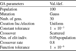
is the error signal. According to LQR performance criteria, Q = 10 and R = 0.001 are settled to regulate controller effort between error and controller in Equation (21). In this way, a tendency to rely more on the sensor measurement and less on the controller is aimed. The GA parameters are shown in Table 2.
Values for the GA parameters

3.2 Linear quadratic regulator (LQR) controller
The LQR controller is used as an optimisation technique involving a quadratic objective function corresponding to the weighted energy of the control variables. The performance criterion in LQR is to select signal u(t) that can minimise the control input u in the
 ${J_{LQR}}$
function given by Equation (22).
 \begin{align}{J_{LQR}} = \mathop {{\textrm{lim}}}\limits_{T \to \infty } {\rm{\;}}\mathop \smallint \limits_0^T \left( {{x^T}.Q.x + {u^T}.R.u} \right).dt\end{align}
The result of the states and control signals given by Equation (22), including the weighted energy terms, must be minimised. For this purpose, stabilising Q and R are constructed to meet the transient performance requirements quickly with minimum controller energy. According to R, higher Q values indicate higher system performance and the reverse. The Q matrix is a positive semi-definite matrix. Adjustments were performed according to each state variable’s feedback K gains and simulation results. Similarly, the R matrix is a positive diagonal matrix chosen to adjust the energy and value of the corresponding control signal. The assumptions are as follows:
Assumption 1.
 \begin{align*}Q = {Q^T} \ge 0{\rm{\;\;}}and{\rm{\;\;}}R = {R^T} \gt 0\end{align*}
and (A, B) the pair must be stable.
According to Assumption 1, the optimum controller design is
 $U\left( t \right) = - {K_r}.x\left( t \right)$
, and
 ${K_r}$
denotes the optimum state feedback gain, as in Equation (23).
 \begin{align}{K_r} = {R^{ - 1}}.{B^T}.P\end{align}
P is obtained from the algebraic Riccati equation required for stability.
 \begin{align}{A^T}.P + P.A - P.B.{R^{ - 1}}.{B^T}.P + Q = 0\end{align}
Here, the stability measure refers to the case where the closed-loop matrix A is
 ${A_c} = A - B{R^{ - 1}}{B^T}P$
asymptotically stable. The P matrix is positive, semi-definite and symmetric. The gain and phase margins are improved with good determination of these matrices. LQR has a linear control law for the UAV and minimises the state variables with a second-order cost function.
3.3 Optimum state estimation with Kalman filter
KF is the most common state estimator because it optimally compensates for measurement noise, disturbances and modelling uncertainties. LQG-type control is obtained by combining the KF with LQR control. The disturbance effect
 ${{\textrm{w}}_{\textrm{d}}}$
and sensor noise
 ${{\textrm{w}}_{\textrm{n}}}$
are added to redefine the system as in Equations (24–25).
 \begin{align}\frac{d}{{dt}}x\left( t \right) = A.x\left( t \right) + B.u\left( t \right) + {w_d}\left( t \right)\end{align}
 \begin{align}y\left( t \right) = C.x\left( t \right) + D.u\left( t \right) + {w_n}\left( t \right)\end{align}
The KF is a Gaussian operation with zero mean at known disturbance and noise covariance values.
 \begin{align}{\textrm{E}}({w_d}\left( t \right).{w_d}\left( {\tau {)^T}} \right) = {V_d}.\delta \left( {t - \tau } \right)\end{align}
 \begin{align}{\textrm{E}}({w_n}\left( t \right).{w_n}\left( {\tau {)^T}} \right) = {V_n}.\delta \left( {t - \tau } \right)\end{align}
In Equations (27–28), E is the expected value and
 $\delta $
is the Dirac delta function.
 ${{\textrm{V}}_{\textrm{d}}}$
and
 ${{\textrm{V}}_{\textrm{n}}}$
are matrices that include positive semi-definite disturbance and noise covariances. The KF depends on unknown noise, disturbance and direct effects. It estimates the state
 ${\hat{\textrm{x}}}$
from the state measurements x according to the input u and output y measurements as in Equations (29–36).
 \begin{align}\frac{d}{{dt}}{\hat x} \left( t \right) = A.{\hat x} \left( t \right) + B.u\left( t \right) + {K_f}.\left( {y - {\hat y} } \right)\end{align}
 \begin{align}{\hat y} \left( t \right) = C.{\hat x} \left( t \right) + D.u\left( t \right)\end{align}
The matrices A, B, C and D reflect the UAV model, and the
 ${K_f}$
gain can be obtained similarly for LQR. y is the solution of algebraic Riccati equation,
 \begin{align}{A^T}.Y + Y.A - Y.C.{V_n}^{ - 1}.{C^T}.Y + {V_d} = 0\end{align}
The solution given by Equation (31) is called the KF.
 \begin{align}\frac{d}{{dt}}{\hat x} \left( t \right) = \left( {A - {K_f}.C} \right){\hat x} \left( t \right) + \left[ {{K_f},{\rm{\;\;}}\left( {B{K_f}.D} \right)} \right]\left[ {\begin{array}{*{20}{c}}y\\u\end{array}} \right]\end{align}
3.4 Linear quadratic Gaussian (LQG) controller
Since the assumption that all state variables can be measured in LQR control is not very realistic in terms of application, LQG control theory was preferred. For the LQG controller, disturbance effects are filtered Dryden wind turbulence signals. Leaving aside the measurement logic of all variables in LQR control, LQG control is based on noisy measurements. In this case, two different sub-problem solutions arise. One is the filter design in which the state variables can be optimally estimated and the other is to obtain the optimal controller setting. KF is essential here as the optimal observer that balances disturbance and noise signals. Here, LQR gain
 ${K_r}$
and KF gain
 ${K_f}$
are obtained separately. LQR and KF full-state observer form the LQG controller together. The LQG controller is the controller structure of the dynamic system which has input y, output u, internal state
 $\hat x$
.
 \begin{align}\frac{d}{{dt}}{\hat x} \left( t \right) = \left( {A - {K_f}.C - B.{K_r}} \right){\hat x} \left( t \right) + {K_f}.y\left( t \right)\end{align}
 \begin{align}u = - {K_r}.{\hat x} \end{align}
Equation (33) defines the newly derived matrix A and B for the LQG. Equation (34) is the negative feedback of the
 ${K_r}$
gains containing the LQR controller output. Equation (35) defines the LQG controller’s cost function.
 \begin{align} J\left( t \right) = \mathop \int \limits_0^t [x{(\tau )^T}.Q.x\left( \tau \right) + u\left( {\tau {)^T}.R.u\left( \tau \right)} \right].d\tau \end{align}
The controller
 $u = - {K_r}{\hat x} $
is a cost function related to the state estimation and requires averaging over many realisations of disturbance and noise. If we apply the LQR for
 $\hat x$

The final form for the closed-loop system is given by Equation (37).
 \begin{align}\frac{d}{{dt}}\left[ {\begin{array}{*{20}{l}}x {}\\[2pt]\varepsilon \end{array}} \right] = \left[ {\begin{array}{c@{\quad}c}{A - B{K_r}}& {}{B{K_r}}\\[2pt]0& {}{A - {K_f}C}\end{array}} \right]{\rm{\;}}\left[ {\begin{array}{*{20}{l}}x\\[2pt]\varepsilon {}\end{array}} \right] + \left[ {\begin{array}{c@{\quad}c}I& {}0\\[2pt]I& {}{ - {K_f}} {}\end{array}} \right]{\rm{\;}}\left[ {\begin{array}{*{20}{l}}{{w_d}}\\[2pt]{{w_n}}\end{array}} \right]\end{align}
The LQG block diagram can be found in Fig. 5. For the LQR and KF, the eigenvalues
 $\left( {A - B.{K_r}} \right)$
and
 $\left( {A - {K_f}.C} \right)$
, respectively, provide the closed-loop eigenvalues of the LQG controlled system.
Block diagram of the LQG controller.

3.5 Model reference adaptive control based on MIT rule
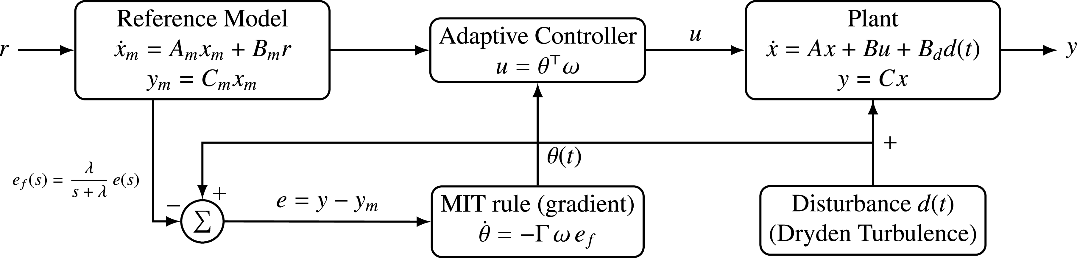
In this paper, the dominant transfer function of the aircraft dynamics is controlled using an MRAC system based on the traditional Massachusetts Institute of Technology (MIT) rule as in Fig. 6. To provide transparency in robustness and disturbance-rejection analysis, the controller is designed inside a single-input, single-output (SISO) architecture.
MIT rule-based MRAC structure with additive disturbance input.

The desired closed-loop system behaviour is given by a stable second-order reference model whose output represents the ideal system response.
 ${\omega _n}$
and
 ${\rm{\zeta }}$
are the natural frequency and damping ratio of the reference model, respectively. The reference model is defined as
 \begin{align}{G_m}\left( s \right) = \frac{{\omega _n^2}}{{{s^2} + 2\zeta {\omega _n}s + \omega _n^2}}\end{align}
The plant dynamics are described by a linear transfer function obtained from the linearised aircraft model. The tracking error is defined as
 \begin{align}e\left( t \right) = y\left( t \right) - {y_m}\left( t \right)\end{align}
and is used for both control law and parameter adaptation. The adaptive controller input is constructed in a PID-type design,
 \begin{align}u\left( t \right) = {K_p}\left( t \right)e\left( t \right) + {K_i}\left( t \right)\mathop \smallint \nolimits_0^t e\left( \tau \right){\rm{\;}}d\tau + {K_d}\left( t \right){\dot e_f}\left( t \right)\end{align}
where the derivative term is used as a first-order filtered error
 \begin{align}{e_f}\left( s \right) = \frac{\lambda }{{s + \lambda }}e\left( s \right)\end{align}
The adaptation laws are obtained using the MIT rule by minimising the cost function J
 \begin{align}J = \frac{1}{2}{e^2}\left( t \right)\end{align}
leading to gradient-based update equations for the controller gains,
 \begin{align} {{{\dot K}_p}} &= -{\gamma_p}{e^2}\left( t \right),\nonumber\\[3pt]{{{\dot K}_i}} &= - {\gamma _i}e\left( t \right)\mathop \smallint \nolimits_0^t \left( \tau \right){\rm{\;}}d\tau , \nonumber\\[3pt]{{{\dot K}_d}} &= - {\gamma _d}e\left( t \right){{\dot e}_f}\left( t \right) \end{align}
where
 ${\gamma _p}$
,
 ${\gamma _i}$
, and
 ${\gamma _d}$
are positive adaptation gains. Dryden turbulence model for moderate level of external disturbances is applied at the plant input, while the reference model remains disturbance-free. This ensures that the adaptive mechanism compensates for model uncertainties and disturbances directly through parameter adjustment. The final MRAC design provides improved robustness compared to fixed-gain controllers and offers a clear benchmark for comparison with PID, LQR and LQG designs.
4.0 Simulation and experimental results
4.1 Cessna-182 longitudinal motion controller results
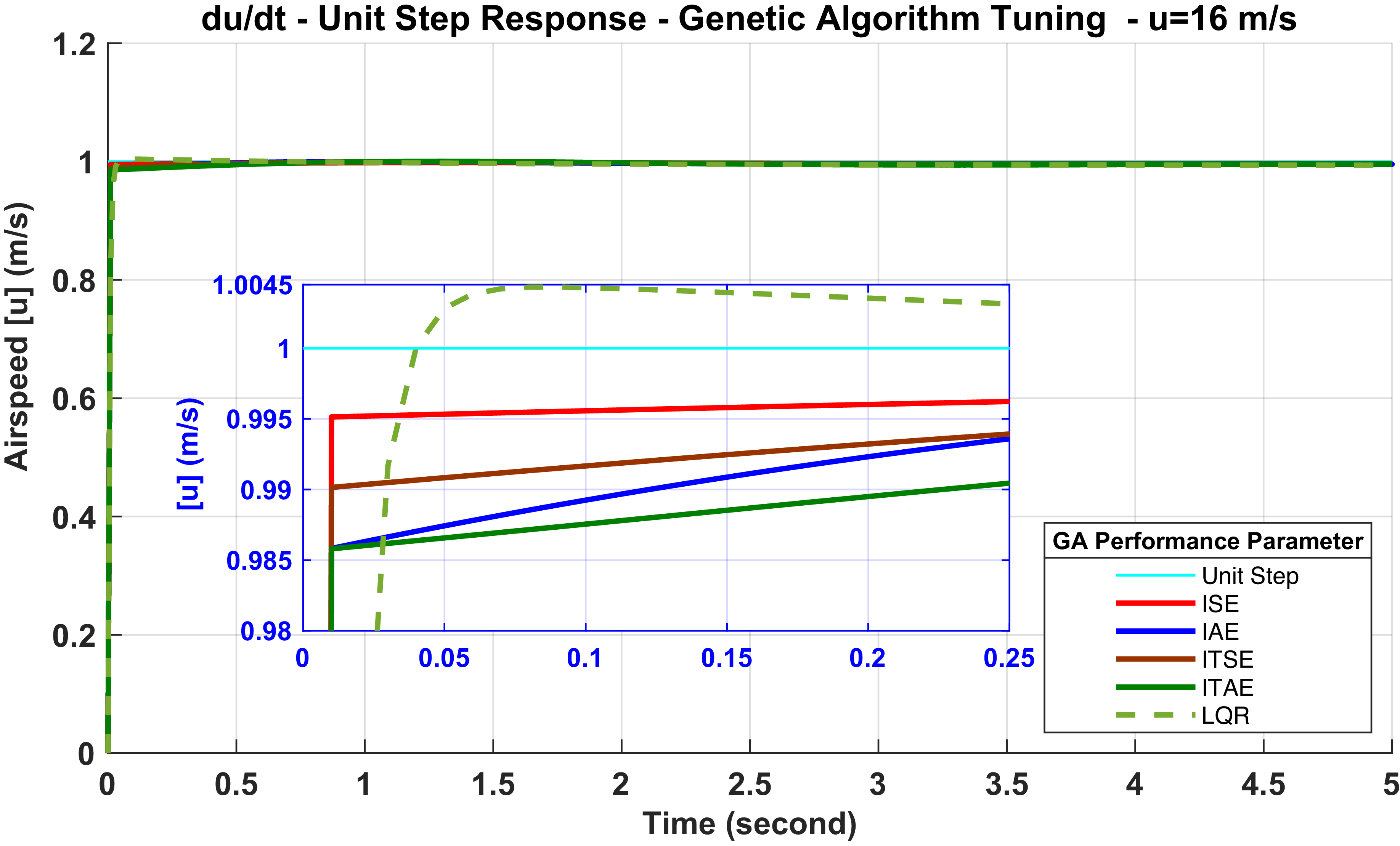
ZN, RL, GA and MT were used to determine the gains of the PID controller. The simulation results obtained with PID (ZN), PID (RL), PID (GA), PID (MT), MRAC are given. Figures 7–10 show the results of the PID (GA) controller for the flight speed (u), downward speed (w), pitch rate (q) and pitch angle
 $(\theta)$
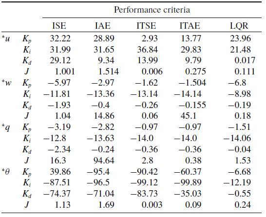
dynamics. In the appendix, Tables A2–A3 show the gain parameters
 $K_p$
,
 $K_i$
and
 $K_d$
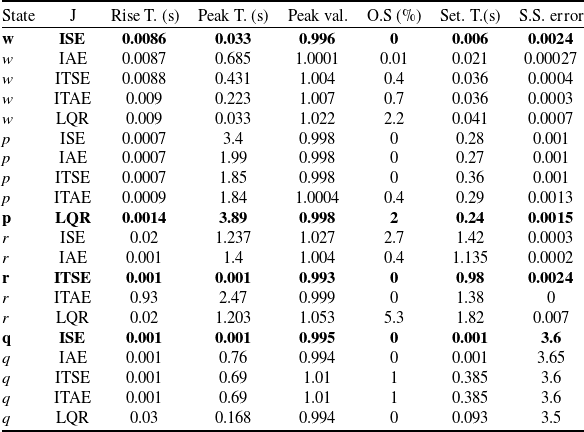
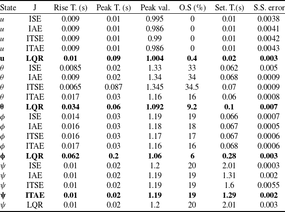
obtained from the GA optimisation. The J term, which is the cost function of each performance parameter, is also aimed to be minimal. Especially for the LQR criterion, Q = 10 and R = 0.001 were chosen to reduce the load on the controller and reduce overshoot. Considering the controller effort, GA responses for the LQR performance criterion were generally preferred. GA settings show much better results than the PID (ZN) method as seen in Tables 3–4.
PID(GA) – flight speed (u) unit step.

Figure 7 Long description
A line graph titled du/dt - Unit Step Response - Genetic Algorithm Tuning - u equals 16 meters per second. The horizontal axis represents Time in seconds ranging from 0 to 5 seconds. The vertical axis represents Airspeed in meters per second ranging from 0 to 1.2 meters per second. The graph includes a legend with labels for Unit Step, ISE, IAE, ITSE, ITAE, and LQR. The Unit Step line is cyan and remains constant at 1 meter per second. The ISE line is red and shows a gradual increase. The IAE line is blue and shows a slower increase compared to ISE. The ITSE line is brown and shows a moderate increase. The ITAE line is green and shows the slowest increase. The LQR line is a dashed green and shows a rapid initial increase followed by a leveling off. An inset zooms in on the time range from 0 to 0.25 seconds and airspeed range from 0.98 to 1.0045 meters per second, highlighting the initial responses of the different parameters.
PID(GA) – downward speed (w) unit step.

PID(GA) – pitch rate (q) unit step.

Figure 9 shows that the GA performed flawlessly when parameters such as overshoot and settling time were analysed. In controlling the pitch rate, the integral of squared error (ISE) was preferred as it has a better rise time and settling time than other criteria. As seen in Fig. 9, there is no overshoot. The controller results show that the error increases slightly with time. The ISE and integral of absolute error (IAE) performance are very fast regarding rise time for the pitch angle. In general, the PID gains for the LQR criterion are taken as the best case since the LQR is achieved stably in a very short time in terms of steady-state error.
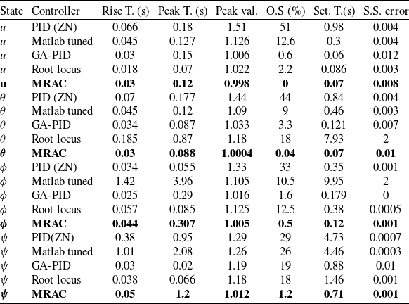
To show the optimum PID parameters obtained with GA more clearly, PID(ZN), PID(MT) and PID(RL) and MRAC controller results are compared in Figs 11–12 for flight speed and pitch angle. As seen in both figures, the MRAC controller performance indicated the best result.
Step result comparisons for GA criteria

PID(GA) – pitch angle (
 $\theta $
) unit step.

In Fig. 12, the overshoot for the pitch angle is high for PID(ZN) and PID(RL), but PID(GA) is acceptable for settling time. Overall results in Table 5 show that the MRAC controller exhibited less overshoot, a fast rise time and a settling time, even in the presence of a moderate level of Dryden turbulence. The MRAC controller can be preferred in this situation.
Step result comparisons for GA criteria (contd.)

PID results – flight speed (u) unit step.

Controller performance comparison for selected states

PID results – pitch angle (
 $\theta $
) unit step.

4.2 Controller results of the lateral motion
The results of the lateral dynamics of roll rate (p), yaw rate (r), roll (
 $\phi $
) and yaw angle (
 $\psi $
) are presented. (p) has the simulation output shown in Fig. 13 among the lateral dynamics. All performance criteria responded quite fast. The ISE criterion has the fastest settling time.
Figure 14 shows that the integral of time-weighted squared error (ITSE) for (r) control stands out with the fastest settling and lowest overshoot. In the unit step response for roll angle (
 $\phi $
) control given in Fig. 15, the LQR criterion stands out regarding very low overshoot and acceptable settling speed. The LQR was preferred as the controller with low overshoot as seen in Table 4.
PID(GA) – roll rate (p) unit step.

PID(GA) – yaw rate (r) unit step.

PID(GA) – roll angle(
 $\phi $
) unit step.

Figure 16 and Table 4 show that the yaw angle responses are close to each other. However, the integral of time-weighted absolute error (ITAE) performance criterion regarding steady-state error and settling time is accepted.
PID(GA) – yaw angle(
 $\psi $
) unit step.

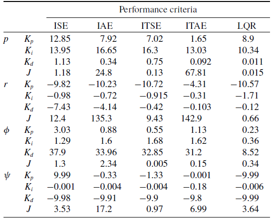
The lateral dynamic controller gains and J cost function values obtained by optimisation for different criteria using GA are given in Appendix Table A3. Figures 17–18 and Table 4 results, the MRAC controller represents much better settling time and less overshoot and the MRAC design exhibits a stable result under Dryden wind moderate turbulence conditons. It is acceptable to use the UAV at a moderate level of wind.
Different PID tuning – roll angle (
 $\phi $
) unit step.

PID results – roll angle (
 $\psi $
) unit step.

4.3 LQR, LQG and MRAC simulation results
4.3.1 LQR, LQG, MRAC longitudinal motion results
The longitudinal motion simulation results of the LQR controller are given in this section. As mentioned in the previous section explaining the LQR, the system’s feedback coefficients (K) are found, and the closed-loop simulation results are obtained. Defining the
 ${\textrm{Q}}$
and
 ${\textrm{R}}$
matrices is necessary to minimise this criterion according to the determined performance criterion.
The ratio between
 ${\textrm{Q}}$
and
 ${\textrm{R}}$
should be well-determined to obtain the best performance value by minimising
 ${{\textrm{J}}_{{\textrm{LQR}}}}$
defined by Equation (22). If the value of R matrix is larger than Q matrix, the settling time will increase. On the contrary, if Q matrix is larger than R matrix, the settling time will decrease.
For the state space longitudinal motion of the Cessna-182, the LQR feedback gains
 ${K_r}$
were obtained by selecting Q and R optimally in Equation (44) as a result of the trials. Here, the diagonal terms belong to the state variables u, w, q,
 $\theta $
, h, which are
 ${Q_{11}}$
,
 ${Q_{22}}$
,
 ${Q_{33}}$
,
 ${Q_{44}}$
and
 ${Q_{55}}$
, respectively. Here,
 ${\textrm{h}}$
is altitude and
 ${\textrm{w}}$
is emphasised more to provide altitude control.
 \begin{align}R = 1,Q = {\textrm{diag}}\left( {50,{\rm{\;\;}}100,{\rm{\;\;}}0.001,{\rm{\;\;}}0.001,{\rm{\;\;}}200} \right)\end{align}
The resulting
 ${K_r}$
feedback gains are:
 \begin{align}{K_r} = \left[ {\begin{array}{c@{\quad}c@{\quad}c@{\quad}c@{\quad}c}{7.07}& {}{ - 0.49}& {}{0.05}& {}{8.56}& {}{ - 1.16}\\{ - 0.01}& {}{ - 6.29}& {}{ - 1.51}& {}{ - 65.12}& {}{14.1}\end{array}} \right]\left[ {\begin{array}{*{20}{l}}{{\delta _T}} {}{} {}{} {}{} {}{} {}{} {}{} {}{} {}{} {}{} {}{} {}{} {}{} {}{} {}{} {}{} {}{} {}{} {}{} {}{}\\{{\delta _e}} {}{} {}{} {}{} {}{} {}{} {}{} {}{} {}{} {}{} {}{} {}{} {}{} {}{} {}{} {}{} {}{} {}{} {}{} {}{}\end{array}} \right]\end{align}
The eigenvalues of the new closed loop system
 $\left( {{\textrm{A}} - {\textrm{B}}{{\textrm{K}}_{\textrm{r}}}} \right)$
formed with the found LQR gain are:
 \begin{align}{\textrm{Eigs}} = \left\{ { - 97.75 \pm 74.75i,{\rm{\;\;}} - 48.15,{\rm{\;\;}} - 2.35 \pm 1.34i} \right\}\end{align}
KF gains are required in addition to the LQR gains for the LQG control. If the altitude is monitored, the LQG can observe and control the system. The disturbance, noise covariances
 ${V_d}$
and
 ${V_n}$
for the KF given by Equation (47) were both selected as 0.1 to represent moderate uncertainty, providing a balanced trade-off between estimation responsiveness and noise amplification while avoiding overly aggressive or excessively sluggish Kalman filter behaviour.
 \begin{align}{V_d} = 0.1 \cdot {I_5},{\rm{\;\;\;\;}}{V_n} = 0.1\end{align}
Here, the new matrix B is obtained as
 ${B_{new}}$
= [B Vd 0 * B] and the matrix D is as
 ${D_{{\textrm{new}}}} = \left[ {0{\rm{\;\;}}0{\rm{\;\;}}0{\rm{\;\;}}0{\rm{\;\;}}0{\rm{\;\;}}0{\rm{\;\;}}0{\rm{\;\;}}0{\rm{\;\;}}0{\rm{\;\;}}0{\rm{\;\;}}{V_n}} \right]$
and the
 ${{\textrm{K}}_{\textrm{f}}}$
gains, are given in Equation (48).
 \begin{align}{K_f} = \left[ {\begin{array}{*{20}{l}}{0.71}\quad {}{0.07}\quad {}{0.062}\quad {}{ - 0.074}\quad {}{1.51} {}{} {}{} {}{} {}{} {}{} {}{} {}{} {}{} {}{} {}{} {}{} {}{} {}{} {}{} {}{}\end{array}} \right]\end{align}
The eigens of the state observer KF, i.e. poles and zeros, are obtained as in Equation (49). The poles are in the left half plane of the virtual axis, and the state observer KF is in steady-state.
 \begin{align}{\textrm{Eigs}}\left( {A - {K_f}C} \right) = \left\{ { - 0.1,{\rm{\;\;}} - 0.72 \pm 1.19i,{\rm{\;\;}} - 6.75 \pm 5.4i} \right\}\end{align}
According to the gains, the LQR noisy and noiseless state-space simulation results of the longitudinal model and the LQG noisy results are analysed. Since the KF required for using the LQG is a reasonable observer for noisy conditions, it is preferred for LQG design.
The results of the velocity and angle change in response to the altitude input to be controlled are shown in Fig. 19. The pitch angle changes by about 0.08 rad (4.58°) during the altitude increase and tries to settle around the equilibrium position (0°) when altitude is achieved. Here, the results of the LQR technique were realised relatively fast and without overshooting in the noiseless state; however, a Dryden wind moderate continuous turbulence was added to all state variables via Matlab Simulink by using Dryden block to model the external disturbance effect on the system. The noise variance was 0.1. In addition, to model the sensor noise in the system, a sensor noise with a variance of 0.01 was added to the sensor measurement sent to the KF, and the noisy state’s results were examined. The results clearly show that the LQR controller is more affected by noise and disturbance input. For this reason, it is seen that the system is less affected by disturbances with the LQG controller with the intuition of the noisy state of the examined KF. In addition to the LQG, the MRAC controller shows the best performance in terms of disturbance rejection and tracking accuracy.
Altitude (h) control (LQR, LQG and MRAC) at Dryden turbulence.

In Fig. 20, a signal was input for altitude from 50 m to 100 m for ascent, constant altitude and descent, and the results were compared.
(h,u,
 $\theta $
) LQR and LQG results.

Fig. 20 clearly shows that the given reference altitude signal is followed by LQR and LQG controllers, but the LQR is much more affected by the noise and disturbance input signal. The ramp signal was defined for the UAV moving at a constant altitude, and the ascent was 100 m. Then, the wing-level flight was parallel to the ground, and the descent signal was followed at 50 m. During this time, the flight speed is 60 km/h. The pitch angle changes during ascent and descent show that the pitch angle remains constant during ascent and returns to the equilibrium angle when altitude is achieved. In general, the results show that the LQG controller is effective against noise, and therefore, the LQR + KF structure is valid and can be chosen at uncertain conditions. Beyond that the MRAC controller again demonstrates superior tracking performance and disturbance rejection compared to both LQR and LQG controllers under the same conditions.
4.3.2 LQR, LQG, MRAC lateral motion results
For the lateral dynamics of the Cessna-182 model, the weighting matrices Q and R were selected as shown in Equation (50), and the LQR feedback gains
 ${K_r}$
were obtained. Here, the diagonal terms
 ${Q_{11}}$
,
 ${Q_{22}}$
,
 ${Q_{33}}$
,
 ${Q_{44}}$
and
 ${Q_{55}}$
correspond to the state variables v, p, r,
 $\phi $
and
 $\psi $
, respectively. These state variables represent the sideslip velocity, roll angular velocity, yaw angular velocity, roll angle and yaw angle, respectively. In this case, greater weighting was applied to the roll angle
 $\phi $
and yaw angle
 $\psi $
to ensure effective control of these angles, and the necessary gain values were obtained.
 \begin{align}R = 0.1,{\rm{\;\;\;\;}}Q = {\textrm{diag}}\left( {0.1,0.1,0.1,100,100} \right)\end{align}
The obtained LQR feedback gains (
 ${{\textrm{K}}_{\textrm{r}}}$
) form a 2
 $ \times $
5 gain matrix, as there are two lateral control inputs: aileron (
 $\delta a$
) and rudder (
 $\delta r$
).
 \begin{align}{K_r} = \left[ {\begin{array}{l@{\quad}l@{\quad}l@{\quad}l@{\quad}l}{-0.27}& {}{0.99}& {}{0.04}& {}{31.68}& {}{0.24}\\[5pt]-0.58 & {0.02} & {- 1.66}& {}{ - 0.88}& {}{ - 31.62}\end{array}} \right]\left[ {\begin{array}{*{20}{l}}{{\delta _a}} {}{} {}{} {}{} {}{} {}{} {}{} {}{} {}{} {}{} {}{} {}{} {}{} {}{} {}{} {}{} {}{} {}{} {}{} {}{}\\{{\delta _r}} {}{} {}{} {}{} {}{} {}{} {}{} {}{} {}{} {}{} {}{} {}{} {}{} {}{} {}{} {}{} {}{} {}{} {}{} {}{}\end{array}} \right]\end{align}
The eigenvalues of the new closed-loop
 $\left( {{\textrm{A}} - {\textrm{B}}.{{\textrm{K}}_{\textrm{r}}}} \right)$
formed by the LQR gains:
 \begin{align}{\textrm{Eigs}} = \left\{ { - 191.5,{\rm{\;\;}} - 3.192,{\rm{\;\;}} - 31.46,{\rm{\;\;}} - 18.83 \pm 21.15i} \right\}\end{align}
As shown in Equation (52), the eigens are located in the left half of the complex plane, with real and complex conjugate roots. Since no poles are in the right half-plane, the system is controlled stably. For LQG control, the KF gains were obtained. As discussed in Section 4, the system is observable when the yaw angle
 $\psi $
is tracked, and it was explained that the system can be controlled using LQG. The disturbance and noise covariance matrices
 ${V_d}$
and
 ${V_n}$
for the KF are given in Equation (53) as explained in Equation (47).
 \begin{align}{V_d} = 0.1 \cdot {I_5},{\rm{\;\;\;\;}}{V_n} = 0.1\end{align}
The solution to KF gains is given in Equation (54):
 \begin{align}{K_f} = \left[ {\begin{array}{*{20}{l}}{6.9x{{10}^{ - 4}}}\quad {}{ - 1.01x{{10}^{ - 3}}} {}\quad {7.98x{{10}^{ - 3}}}\quad {}{1.4x{{10}^{ - 2}}} {}{0.13} {}{} {}{} {}{} {}{} {}{} {}{} {}{} {}{} {}{} {}{} {}{} {}{} {}{} {}{} {}{}\end{array}} \right]\end{align}
The eigenvalues of the KF are given in Equation (55):
 \begin{align}{\textrm{Eigs}}\left( {A - {K_f}.} \right) = \left\{ { - 35.7,{\rm{\;\;}} - 4.05 \pm 2.1i,{\rm{\;\;}} - 0.1 \pm 0.08i} \right\}\end{align}
As seen in Equation (55), the poles are located in the left half-plane, which indicates that the KF is stable. Figure 21 shows the results for the other state variables in response to a 10° step input for roll angle control. The control surfaces (aileron and rudder) were limited to
 $ \mp 40^\circ $
using a saturation block in Simulink to reflect realistic conditions. The figure compares the noisy and noise-free responses of LQR with the noise of LQG for roll angle control.
Roll angle (
 $\phi $
) control and other states.

The desired roll angle was achieved relatively quickly, while the other state variables exhibited changes until the roll angle settled, after which they stabilised. Both disturbance and sensor noise were introduced into the system to simulate the effects of noise. The variance of the randomly generated MATLAB Simulink noise was set to 0.01. In terms of noise, it was observed that the LQR feedback was more affected by noise. In contrast, the LQG, benefiting from the KF, effectively suppressed the noise. For the yaw angle (
 $\psi $
), a
 $10^\circ $
step input simulation results are shown in Fig. 22. The MRAC controller also demonstrates robust performance in tracking the yaw angle command under similar noisy conditions, outperforming both LQR and even LQG controllers.
Yaw angle (
 $\psi $
) control and other states.

As in Fig. 22, the yaw angle settled within approximately 1 second, during which the sideslip and yaw angular velocity also exhibited changes. Once the system reached a steady state, the state variables converged to zero as expected. Additionally, the yaw condition only slightly affected the roll angular velocity and angle, settling to zero after minimal angular changes. When evaluating controller performance, it is evident that the LQG controller responded well to noise. In contrast, unlike its noise-free performance, the LQR controller exhibited significant oscillations in the presence of noise. But, the MRAC controller was preferred because of its fast and stable performance under same disturbance effects
As a result of the studies conducted, the proposed MRAC and GA-based PID parameter tuning, MATLAB PID tuning, RL design and ZN were implemented. Furthermore, full-state feedback control with LQR were explored to better demonstrate the interactions between all state-space variables and control inputs of the UAV. In noisy as well as noise-free conditions, the MRAC provides a flexible and adaptive response based on the transfer function. While LQG has an advantage over LQR due to its full-state design, MRAC offers more adaptable performance under varying conditions.
4.4 Frequency-domain robustness analysis
To analyse the robustness of the system dynamics, frequency-domain analyses were conducted using Bode diagrams. Figures 23–24 present the magnitude and phase responses of the altitude, pitch-angle, roll-angle and yaw-angle channels, respectively. The frequency-domain study shows that under open-loop operation, the longitudinal dynamics show marginal or even unstable behaviour, with poles near the imaginary axis and negative phase margins. The drastically decreased phase margins suggest poor robustness and significant sensitivity to parameter uncertainty and disturbances, even though some channels have reasonably substantial gain margins. On the other hand, even if some channels are operating near the stability boundary, the lateral dynamics show more favourable stability margins and remain open-loop stable with respectable gain and phase characteristics.
Bode diagrams: (a) altitude response (b) pitch-angle response.

Bode diagrams: (a) roll angle response (b) yaw-angle response.

Both longitudinal and lateral dynamics show notable increases in stability margins when closed-loop control, such as the MRAC and LQG controller, is used. Increased phase margins and decreased sensitivity to disturbances are evaluated by using the MRAC and LQG controllers. While the LQG controller successfully reduces the effects of noise and disturbances through optimal state estimation, the MRAC controller specifically improves robustness by adaptively responding to changing dynamics. Overall, the frequency-domain analysis verifies that the suggested control solutions significantly improve the stability and resilience of the UAV dynamics in both lateral and longitudinal motions.
4.5 Flight test results
Cessna-182 mini-UAV was used for flight tests. The aim was to compare the PID parameters obtained from simulation results. Several successful flights were carried out, and PID tuning was performed in real-time using the Mission Planner ground station software. The resulting PIDs are presented. The PIDs for roll and pitch angles were obtained during real-time flight using Mission Planner, and their proximity to the values derived from simulation results was examined.
During the flight, the UAV successfully executed roll, pitch, and yaw angle commands despite windy conditions, and the obtained PIDs were found suitable for controlling the aircraft. All hardware and the plan were prepared using the Pixhawk Cube controller board and the Mission Planner. The accelerometer, compass, radio controller, airspeed sensor and ESC motor were calibrated using ArduPilot instructions. Additionally, flight modes (manual, stabilise, mission, return-to-launch, FBWA) were configured on the controller. To ensure communication via telemetry, the RFD900x modem was used, operating in the 915–928 MHz frequency band with 21 channels. Necessary data were monitored through the autopilot during the flight.
In addition to previous flight tests, some information and the flight path obtained during this flight are shared. Figure 25 shows the GPS data for the flight during the PID auto-tuning attempt at the Talas model aircraft runway. The red trajectory represents the flight path during PID tuning, while the yellow trajectory represents the flight path in stabilise mode using the tuned PID parameters.
(a) Auto-PID tuning; (b) second flight route at stabilise mode.

Figure 25(b) shows the automatic PID adjustment during real-time flight and the route during the adjustment with red lines. These adjustments continued for about 1.5 turns. Then, the UAV was put into stabilised mode, and the flight continued the route indicated by yellow lines. No abnormality was observed in the aircraft flight despite the windy conditions. Later, the landing was performed successfully, as there was no signal loss or deviation in the control. A flight was conducted for the next attempt to re-adjust the PIDs. Figure 25(b) shows the route of this flight.
The flight was experimented with, and all PID parameters were experimentally adjusted in real time. The results obtained are close to the theoretical results. Figure 26(a) shows the takeoff and Fig. 26(b) was captured while in flight phase. In Appendix Figs A1(b–c) indicate the desired roll and pitch angle versus the measured roll and pitch angle after the Mission Planner auto-tune. In general, desired and measured angle data follow each other. Airspeed data taken from GPS is depicted in Appendix Figure A1(a).
(a) Take off; (b) flight.

5.0 Conclusion
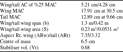
In this study, control systems for UAVs were assessed, ranging from adaptive PID, optimal state-space controllers to traditional PID methods. Some specific aerodynamic coefficients were obtained by ANSYS Fluent after modelled by a computer-aided design programme. The analysis began with PID using ZN tuning, but Matlab’s PID tuning and GA optimisation were explored due to their performance limitations. PID tuning using GA performed noticeably better in dynamic responsiveness than both Matlab’s auto-tuning and Ziegler-Nichols methods.
State-space feedback control was implemented using LQR, KF and LQG methodologies for longitudinal and lateral motions. While LQR provided excellent performance in noise-free conditions, its performance deteriorated significantly in the presence of disturbances and sensor noise. Since UAVs perform in noisy situations, LQG control, integrating LQR with a KF, appeared more robust. Additionally, the MRAC controller demonstrated superior adaptability and disturbance rejection capabilities compared to both LQR and LQG controllers under similar conditions.
The KF within LQG proficiently estimated the dynamic states, reducing the effects of turbulence, sensor noise and disturbances. The selection of
 ${V_d}$
and
 ${V_n}$
covariance matrices was critical in the filter’s response tuning to measurement and process noise. The process noise was chosen based on UAV flight dynamics and environments.
Ultimately, under noisy and disturbed operating conditions, PID-based flight experiments were conducted on a UAV platform equipped with a KF-based state estimation infrastructure originally designed for LQG control. While full LQG and MRAC implementations could not be experimentally evaluated due to hardware limitations, the MRAC controller demonstrated the best overall performance in simulation-based robustness and disturbance rejection analyses.
The state-of-the-art in robust UAV control is advanced by this work, which not only compares traditional PID tuning methods to optimum controllers but also offers a comprehensive framework suitable for small UAVs.
It should be stated that the regulation and disturbance rejection performance of the studied control techniques, which represent the core layer of fixed-wing UAV flight control, are the main emphasis of this work. To ensure a fair and targeted comparison at the stabilisation level, trajectory tracking, waypoint navigation and coupled longitudinal–lateral movement were intentionally omitted out.
Additionally, this study did not specifically address practical implementation issues such actuator saturation, sensor errors and real-time embedded deployment restrictions. These factors are indicated as essential areas for future research, especially for sophisticated adaptive and optimal control structures like MRAC and MPC-based frameworks, together with discrete-time implementation, sampling effects and comprehensive sensor noise characterisation.
Acknowledgements
This study is part of the research project FBA-2018-8391. The authors would like to show appreciation for the economical support supplied by the Scientific Research Projects Coordination Unit of Erciyes University, in accomplishing this study.
Financial support
This study is a work of the research project numbered as FBA-2018-8391.
Competing interests
The authors declare no conflicts of interest. They have no financial, commercial or personal relationships that could influence or be perceived to influence this work. The manuscript is original, has not been published before and is not under consideration elsewhere.
Author contributions
Şaban Ulus: Conceptualisation, data curation, formal analysis, methodology, software, writing – original draft.
İkbal Eski: Investigation, supervision, validation, writing-editing.
Appendix
Cessna-182 parameters

Long. PID gains tuned with GA

Lateral PID gains tuned with GA

(a) Airspeed, (b) Roll angle, (c) Pitch angle.



 ϕ,θ,ψ




 θ


 θ


 ϕ

 ψ

 ϕ

 ψ


 θ

 ϕ

 ψ