I. INTRODUCTION
Composite magnetoelectric (ME) materials combine a magnetostrictive phase and a piezoelectric phase to a ME heterostructure. As in single phase ME materials, the electric properties can be manipulated using an externally applied magnetic field and, vice versa, the magnetic properties using an electric field. Reference Nan, Bichurin, Dong, Viehland and Srinivasan1 This coupling of properties is very interesting, because of the potential for application in multifunctional or highly sensitive devices. Provided that the incorporated materials and processes are compatible, magnetostrictive, and piezoelectric materials can be chosen for the fabrication of ME heterostructures so as to be attuned to the particular application under consideration. Thus, the current limitation of single phase ME materials with regard to magnitude and temperature dependence of the magnetoelectric effect can be circumvented. Reference Nan, Bichurin, Dong, Viehland and Srinivasan1 A thin film approach to layered ME composites additionally increases design flexibility Reference Nan, Hui, Rinaldi and Sun2–Reference Lee, Kim, Yoo, Han, Chun, Kim, Kim, Hwang, Kim, Jo, Kim, Song and Lee4 and enables the exploitation of coupling phenomena such as exchange biasing of the magnetostrictive layers, Reference Lage, Kirchhof, Hrkac, Kienle, Jahns, Knöchel, Quandt and Meyners5 which further increases the usability of the resulting ME devices. This article presents the evaluation of thin film ME heterostructures fabricated on Si cantilevers by means of bulk micromachining. They are investigated as highly sensitive alternating magnetic field sensors.
In a ME cantilever sensor, magnetostrictive strain is generated in response to an external magnetic field by the ferromagnetic layer. This strain leads to a deflection of the cantilever and mechanical stress arises in the piezoelectric layer due to the immanent mechanical coupling across the layer structure. The direct piezoelectric effect produces an electrical field, which can be detected as an electric voltage between the electrodes, e.g., along the piezoelectric thickness direction. As a result the ME effect is a product property Reference Nan, Bichurin, Dong, Viehland and Srinivasan1 and the magnetoelectric voltage V ME generated in response to an alternating magnetic field H AC along the cantilever axis is dependent on the properties of the constituent phases of the composite Reference Piorra6 :
 $${V_{{\rm{ME}}}} = {{{d^{\rm{m}}}_{11}k{e_{31}}} \mathord{\left/ {\vphantom {{{d^{\rm{m}}}_{11}k{e_{31}}} {({\varepsilon _0}{\varepsilon _{33}})z{H_{{\rm{AC}}}}\quad ,}}} \right. \kern-\nulldelimiterspace} {({\varepsilon _0}{\varepsilon _{33}})z{H_{{\rm{AC}}}}\quad ,}}$$
where d m 11 denotes the piezomagnetic coefficient along the magnetic field direction, k = ∂S/∂λ the transfer of magnetostrictive strain to strain in the piezoelectric material, e 31 the transverse piezoelectric charge coefficient, ε0 and ε33 the absolute and relative permittivity in the thickness direction, and z the thickness of the piezoelectric layer. For a better comparison of different heterostructures with various functional layers the magnetoelectric coefficient αME is introduced:
 $${\alpha _{{\rm{ME}}}} = {{{V_{{\rm{ME}}}}} \mathord{\left/ {\vphantom {{{V_{{\rm{ME}}}}} {(z{H_{{\rm{AC}}}})\quad .}}} \right. \kern-\nulldelimiterspace} {(z{H_{{\rm{AC}}}})\quad .}}$$
Recent research demonstrated large values of the order of several V/cm Oe for the ME coefficient for bulk ME laminates. Reference Ryu, Priya, Carazo, Uchino and Kim7,Reference Dong, Zhai, Li and Viehland8 For a metglas/PZT-fiber composite, an extremely high αME ≈ 500 V/cm Oe was achieved by operating the composite in mechanical resonance. Reference Dong, Zhai, Li and Viehland8 Using resonance effects to enhance the ME response is also applicable to thin film ME heterostructures. Reference Zhao, Zhao, Hunter, Suchoski, Gao, Mathews, Wuttig and Takeuchi3,Reference Onuta, Wang, Long and Takeuchi9,Reference Kirchhof, Krantz, Teliban, Jahns, Marauska, Wagner, Knöchel, Gerken, Meyners and Quandt10 Following this route, a ME coefficient as large as 20 kV/cm Oe was reached at mechanical resonance under vacuum conditions. Reference Kirchhof, Krantz, Teliban, Jahns, Marauska, Wagner, Knöchel, Gerken, Meyners and Quandt10 This indicates the high potential of such structures for the design of high sensitivity magnetic field sensors. The fact that ME sensors can be operated at room temperature further facilitates their practical application. In particular, certain medical applications could strongly benefit from the invention of such alternative magnetic field sensors. So far, they rely on the usage of liquid-helium cooled Superconducting Quantum Interference Devices (SQUIDs). However, the need for cooling hinders the introduction of SQUID based measurement methods into the clinical daily routine.
II. MATERIALS AND METHODS
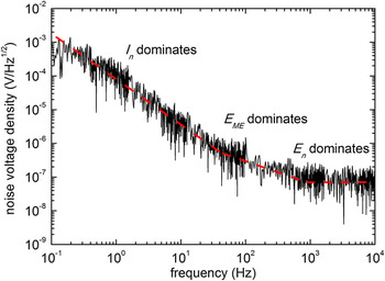
Because the ME voltage is directly proportional to the piezomagnetic and piezoelectric coefficients of the incorporated materials [Eq. (1)], the material selection is most important in terms of magnetic field sensor performance, i.e., sensor sensitivity, sensor noise and, thus, signal-to-noise ratio (SNR). Figure 1 displays an exemplary noise voltage density measurement of a micromachined ME cantilever with 1.8 µm thick AlN and 1.75 µm thick FeCoSiB layers as piezoelectric and magnetostrictive functional phases. Reference Jahns, Greve, Woltermann, Lage, Quandt and Knöchel11 A simple plate-capacitor design was used as the electrode configuration. The measurements were conducted in a magnetically and acoustically shielded set-up to minimize environmental noise sources. An analysis of the intrinsic noise sources of the ME cantilever and the charge amplifier electronics needed for voltage readout revealed three frequency ranges with different dominating noise sources. Reference Jahns, Greve, Woltermann, Quandt and Knöchel12 For low frequencies f below approx. 100 Hz, the current noise sources I n of the operational amplifier govern the noise voltage density, which consequently shows a 1/f dependency. In this frequency range, a large piezoelectric coefficient is mandatory for a high SNR. For frequencies of about 1 kHz and above, a frequency independent voltage noise E n of the operational amplifier dictates the total noise level. The best SNR is observed for a piezoelectric with maximum e 31/ε33 ratio [Eq. (1)]. For medium frequencies in between the two aforementioned ranges the Johnson–Nyquist noise E ME of the piezoelectric phase dominates the magnitude of the noise voltage density. The SNR scales with e 31/(ε0ε33 tan δ)1/2, where tan δ is the dielectric loss tangent. Accordingly, at these frequencies, a piezoelectric material with low dielectric losses should be selected for sensor applications.
Noise voltage density of a ME cantilever sensor readout by a charge amplifier. The dashed line indicates three frequency ranges with different dominating noise sources (I n: current noise sources of the operational amplifier, E ME: Johnson-Nyquist noise of the piezoelectric phase, E n: voltage noise of the operational amplifier). Adapted from Ref. Reference Jahns, Greve, Woltermann, Lage, Quandt and Knöchel11.

In the following, AlN and PZT thin films are considered as representative materials with low dielectric loss factor and large piezoelectric coefficient, respectively. A low-temperature pulsed-DC sputter deposition process has been developed for AlN. Reference Yarar, Hrkac, Zamponi, Piorra, Kienle and Quandt13 The deposition on unheated substrates was carried out with a pure Al target using pure nitrogen as sputtering gas. On a 100 nm thick Pt layer, highly textured c-oriented growth of AlN is achieved. PZT layers were fabricated by chemical solution deposition (CSD). Reference Salzer, Jahns, Piorra, Teliban, Reermann, Höft, Quandt and Knöchel14 The PZT sol was prepared based on lead acetate trihydride, zircon-n-propoxide, titanium-isopropoxide, acetylacetone, and 2-methoxyethanol. It was spin coated on substrates with a 300 nm thick insulating ZrO2 layer, which was also prepared by CSD. In comparison to AlN sputter deposition, a high processing temperature T = 700 °C is required for the crystallization of the PZT films. To increase the total PZT thickness, the procedure can be repeated several times. Table I summarizes the dielectric and piezoelectric properties of AlN and PZT films with a thickness of 2 µm. Within the frequency range where the 1/f current noise sources I n dominate (see Fig. 1), a material with a piezoelectric coefficient as high as possible should be selected to achieve a maximum SNR. According to the e 31 values in Table I, PZT provides a SNR which is 12 times higher than that of AlN. In contrast to that, AlN is the better choice for piezoelectric material at the intermediate frequency range, because of the low dissipation factor and the SNR being proportional to e 31/(ε33 tan δ)1/2. Reference Jahns, Greve, Woltermann, Quandt and Knöchel12 In general, the best SNR can be obtained for high frequencies as the noise voltage density is lowest (see Fig. 1). In addition, here, the SNR scales with the ratio of piezoelectric coefficient over relative permittivity, which favors AlN over PZT again. The low noise level at frequencies above 1 kHz motivates the utilization of a frequency conversion method, which allows picking up low frequency magnetic field signals out of the high noise level range by frequency up-conversion. Reference Jahns, Greve, Woltermann, Quandt and Knöchel15
Dielectric, piezoelectric properties and material dependent factors with impact on SNR for AlN and PZT thin films.

For magnetic field sensor applications, the magnetostrictive phase should exhibit a large piezomagnetic coefficient d m = δλ/δH [Eq. (1)]. Hence, a magnetic material with large saturation magnetostriction and preferably large magnetic susceptibility is demanded. As covered below, the study focuses on ME composites with (Fe90Co10)78Si12B10 layers, because this amorphous alloy combines soft magnetic properties with considerable magnetostriction. Reference Shin, Inoue and Arai16,Reference Greve, Woltermann, Quenzer, Wagner and Quandt17 Sputter deposited FeCoSiB layers show a uniaxial magnetic anisotropy field of approx. 20 Oe and a saturation magnetostriction in the order of one hundred ppm leading to a piezomagnetic coefficient of about 5 ppm/Oe. Reference Greve, Woltermann, Quenzer, Wagner and Quandt17 Besides, because of the low magnetic anisotropy, only small magnetic bias fields are needed to set the ME sensor to its optimum working point, at which the magnetic field dependent piezomagnetic coefficient is at its maximum. Magnetostrictive and AlN layers were fabricated on Si substrates in a sputter deposition cluster tool CS730S manufactured by VON ARDENNE, Dresden, Germany. This tool is equipped with 3 processing chambers and 9 magnetron sputter sources enabling the deposition of complex multilayer systems without breaking vacuum conditions. The magnetostrictive phases with exchange biased magnetic layers were deposited as multilayer systems based on the layer sequence Ta/Cu/Mn70Ir30/FeCoSiB. The antiferromagnetic MnIr imposes a unidirectional anisotropy on the FeCoSiB layer, which can be adjusted in magnitude and direction by layer thickness control and magnetic field cooling, respectively. Reference Lage, Kirchhof, Hrkac, Kienle, Jahns, Knöchel, Quandt and Meyners5 Consequently, instead of applying an external magnetic bias field, the properly tuned unidirectional anisotropy can be utilized to set the optimum working point of such a ME sensor with exchange biased magnetostrictors. The Ta/Cu bi-layer works as seed layer to initiate oriented growth of MnIr in [111] direction. Furthermore, magnetization reversal of magnetic multilayers can be completely different compared to that of micron thick single layers. Hence, the multilayer approach should allow the fabrication of specially tailored multilayers to control the magnetization reversal with the aim to reduce magnetic contributions to the overall sensor noise. Magnetic noise contributions from the magnetostrictive phase are of major concern for magnetically modulated sensors, which are under consideration in Sec. III. C.
Using bulk micromachining for the fabrication of ME heterostructures offers the opportunity for processing of Si substrates on their top and rear sides. Reference Zabel, Kirchhof, Yarar, Meyners, Quandt and Faupel18 Deposition of magnetostrictive and piezoelectric materials on opposite sides of a double-side polished substrate provides a well-defined surface with low roughness for both functional phases. This promotes a smooth growth of the layers within the magnetostrictive multilayers with single layer thicknesses of a few nm. In addition, textured growth is more easily controlled. Structuring of the functional layers was done by standard optical lithography and a combination of wet chemical etching, dry etching, and lift-off techniques. Maintaining a minimum separation of a few hundred microns between functional layers and blade, individual cantilevers were cut with a dicing saw. Typical cantilever dimensions are a length of 25 mm, a width of 2.2 mm, and a thickness of 300 µm. Detailed information on the sensor layout is provided in Table SI. Several layouts make use of the magnetostrictive phase as sensor electrode. In case of AlN based ME sensors, the counter-electrode was implemented as a Cr/Au or Ta/Pt bilayer confined to an area close to the cantilever clamping, where mechanical stress is at its maximum. On PZT grown on insulating ZrO2 interdigital (ID) electrodes can be used on top of the PZT which leads to a sensor design with additional degrees of freedom compared to the simple parallel plate design used for AlN ME sensors. The application of ID electrodes results in a utilization of the longitudinal piezoelectric effect described by e 33, which is about two times larger than the transverse piezoelectric coefficient e 31. Reference Piorra, Jahns, Teliban, Gugat, Gerken, Knöchel and Quandt19 Moreover, the electrode spacing [parameter z in Eq. (1)] is not determined by the piezoelectric layer thickness anymore and can be adjusted independently. As a final step of sensor fabrication, magnetic field annealing at a temperature T = 250 °C and a magnetic field H ≥ 800 Oe and subsequent cooling in presence of H was performed to align the magnetic anisotropies.
The magnetoelectric characterization was carried out in a cylindrical system inclosing two coils. One of the coils, connected to a battery, generated an optional static bias field H BIAS without introducing noise contributions due to current supply fluctuations. The second coil was used to apply a small alternating magnetic field H AC. In measurements of the ME coefficient αME, the RMS amplitude of H AC was typically set to 1 mOe. The frequency f AC of the applied magnetic field could be tuned to match the mechanical resonance frequencies f res of the cantilevers. Both the optional static and the alternating magnetic fields were aligned parallel to the long cantilevers axis. A low-noise charge amplifier was connected to the sensor electrodes and the amplified ME signal was detected by means of lock-in technique. If not otherwise stated, the integration time of the lock-in amplifier equaled 1 s. In case of a tuning fork-like sensor assembly, a more complex analog pre-processing stage including two charge amplifiers, filters, and an instrumentation amplifier was used. Reference Salzer, Jahns, Piorra, Teliban, Reermann, Höft, Quandt and Knöchel14 The whole set-up was placed in a magnetically and acoustically shielded environment (for a detailed discussion of the shielding equipment see Ref. Reference Jahns, Greve, Woltermann, Lage, Quandt and Knöchel11). The minimum detectable amplitude of an alternating magnetic field, at which the ME signal reaches the noise floor, determines the limit of detection (LOD). In LOD measurements the amplitude of H AC was continuously decreased starting from values at least three orders of magnitude larger than the minimum detectable field. A special measurement technique applies frequency conversion to enhance the sensor sensitivity (described by αME) to magnetic field signals with frequencies different than f res. For this purpose, instead of a constant bias field a modulation field H mod with frequency f mod was applied.
III. RESULTS AND DISCUSSION
In the succeeding sections, three approaches to ME alternating magnetic field sensors with high sensitivity and low limit of detection are discussed. These measures are based on exploitation of stress enhancement at resonance, exchange biased magnetostrictive multilayers, and magnetic sensitivity modulation. Finally, the achievements in terms of the detection limit are compared to typical magnetic field amplitudes in medical applications.
A. Resonant magnetoelectric cantilevers
The cantilever design allows for the excitation of the mechanical resonances using an external alternating magnetic field. Considering the first bending mode, the amplitude of the cantilever deflection reaches its maximum after a settling time
 $$\tau = {Q \mathord{\left/ {\vphantom {Q {\left( {\pi {f_{{\rm{res}}}}} \right)\quad ,}}} \right. \kern-\nulldelimiterspace} {\left( {\pi {f_{{\rm{res}}}}} \right)\quad ,}}$$
where Q and f res denote quality factor and resonance frequency. Accordingly, mechanical stress in the piezoelectric is enhanced and Q enters the equation for the generated ME voltage:
 $${V_{{\rm{ME}}}}\left( {{f_{{\rm{res}}}}} \right) = {{Q{d^{\rm{m}}}_{11}k{e_{31}}} \mathord{\left/ {\vphantom {{Q{d^{\rm{m}}}_{11}k{e_{31}}} {({\varepsilon _0}{\varepsilon _{33}})z{H_{{\rm{AC}}}}}}} \right. \kern-\nulldelimiterspace} {({\varepsilon _0}{\varepsilon _{33}})z{H_{{\rm{AC}}}}}}\quad .$$
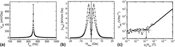
Figure 2(a) shows a measurement of V ME as a function of f AC for an exemplary Si cantilever with a ME functional layer stack Ta 15/FeCoSiB 2970/Ta 15/Pt 150/AlN 1600/Cr 5/Au 100 [thickness in nm]. The magnetic anisotropy of the FeCoSiB layer was aligned perpendicular to the long cantilever axis. H AC and H BIAS were applied along this cantilever axis. The enhancement of the ME voltage for a particular frequency f AC is evident from the graph. At its maximum, V ME amounts to about 1 V/Oe for 867 Hz, which is the first bending mode resonance frequency f res of the millimeter sized cantilever. Out of resonance, the ME voltage is reduced by a factor of 1/Q ≈ 1/500. In Fig. 2(b) the absolute value of the ME coefficient is plotted as a function of the bias magnetic field H Bias. During the measurement, f AC was tuned to the resonance frequency. Since the piezomagnetic coefficient is magnetization dependent, the hysteretic behavior of the piezomagnetic phase transfers to the ME coefficient, which reaches its maximum |αME,max| = 6.9 kV/cm Oe at H BIAS = ±2.4 Oe. These two features of ME behavior, enhancement by mechanical resonance and bias field dependence, are typical for ME cantilever sensors with a single magnetostrictive layer. As a result, resonance frequency and optimum bias magnetic field set the working point of such devices. Without operating them actively, i.e., by applying a magnetic modulation field or an electrical driving field, the sensor bandwidth is given by the width of the resonance curve.
ME properties of a cantilever sensor based on a single FeCoSiB layer and AlN as piezoelectric phase. (a) ME voltage versus f AC for H AC = 1 mOe. An optimum static field H Bias = 2.4 Oe was applied for maximum ME response. (b) Absolute value of the ME coefficient versus H Bias for H AC = 1 mOe and f AC tuned to f res = 876 Hz. (c) ME voltage versus H AC at the optimum working point (H Bias = 2.4 Oe and f AC = 876 Hz). Solid lines indicate linear fits of V ME and the noise level. Their intersection determines the limit of detection (arrow). (b) and (c) are adapted from Ref. Reference Röbisch, Yarar, Urs, Teliban, Knöchel, McCord, Quandt and Meyners20.

For the optimum working point, the detection limit was determined [Fig. 2(c)]. Reducing H AC continuously, first a linear decrease of the ME voltage output is observed over several orders of magnitude of alternating magnetic fields. Finally, the voltage noise floor covers the ME signal and the sensor output is not correlated to H AC anymore. Linear fits of the ME signal and the noise floor are calculated. Their intersection appoints the LOD, at which the SNR equals 1. From the measurement it is derived that the detection limit is in the order of 1 pT/Hz1/2, which is a representative result for this kind of resonant micromachined cantilever sensors. Reference Röbisch, Yarar, Urs, Teliban, Knöchel, McCord, Quandt and Meyners20
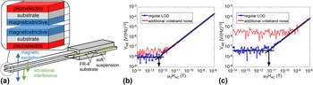
Utilization of vibrating structures for sensing purposes holds the potential risk of cross-sensitivity to environmental noise sources such as acoustic waves and structure-born sound. These types of noise can lead to mechanical vibrations of the sensing unit. In case of a ME cantilever sensor, such vibrations are transferred to the sensor output via piezoelectricity and interfere with the ME signal. Special designs for noise rejection in laminated ME sensors have been proposed based on the fundamental observation that the ME signal should occur in one oscillatory mode, whereas noise actuation should be restricted to another mode. Reference Xing, Zhai, Li and Viehland21 A structural design concept fulfilling this requirement, could be a ME laminate, which enables a mechanically symmetrical response to an applied magnetic field and only asymmetrical responses to vibrational noise. Following this general route, it has been proposed to make use of a tuning fork-like assembly of two ME sensors as it is depicted in Fig. 3(a). Reference Salzer, Jahns, Piorra, Teliban, Reermann, Höft, Quandt and Knöchel14 The two sensors have an asymmetric layer stack with the piezoelectric and magnetostrictive phases on opposite cantilever sides. Since the sensors are placed opposing each other, a magnetic field causes an upward deflection of one of the cantilevers, whereas the other cantilever will bend downwards. In this sense, an applied alternating magnetic field generates a mechanically mirror symmetrical response of the sensor pair. Due to the deflections the piezoelectric layers on both cantilevers are either under compressive or tensile stress simultaneously, i.e., the ME signals are in phase. By contrast, vibrational interference predominantly produces cantilever deflections in the same direction. Hence, vibrational interference leads to voltage outputs of the upper and lower cantilevers being opposite in phase. During a measurement, the sum signals can serve as a measure of the applied magnetic field, whereas the difference contains information about interfering disturbances. Overall, the tuning fork like assembly results in a magnetic sensor structure that is more robust against acoustic waves and structure-borne noise. A prerequisite for the construction is that the constituent cantilever sensors match in their mechanical and magnetoelectric properties. This emphasizes the need for sensor fabrication based on micromachining on wafer level, because it provides high reproducibility of all physical properties.
(a) Tuning fork-like assembly of two ME cantilever sensors. The inset shows details of the layer stack configuration. (b) ME voltage versus H AC using the in phase signals of both ME cantilevers with and without application of wideband noise. (c) displays the corresponding measurements of a single cantilever sensor. Adapted from Ref. Reference Salzer, Jahns, Piorra, Teliban, Reermann, Höft, Quandt and Knöchel14.

Figure 3(b) displays a measurement of the detection limit for two ME cantilever sensors combined to a tuning fork as described in more detail in Ref. Reference Salzer, Jahns, Piorra, Teliban, Reermann, Höft, Quandt and Knöchel14. The sensors with ID electrodes consist of the layers Ta 5 nm/FeCoSiB 4 µm/Si 300 µm/ZrO2 300 nm/PZT 2 µm/Cr 5 nm/Au 100 nm. The first bending mode oscillation occurs at a frequency f res = 958 Hz. In Fig. 3(c) the LOD determination of an identically constructed single sensor is shown. In absence of any artificially induced disturbing influences, its LOD is about 5 pT/(Hz)1/2 (blue crosses). By superimposing additional wideband noise using a piezoelectric loudspeaker, the voltage noise level increases by almost two orders of magnitude and the detection limit is worsened by the same amount (red dots). In contrast to that, the noise level of the assembled sensors increases by a factor of only 4, if the external noise source is operated. This shows that the tuning fork-like assembly is by far less sensitive to acoustic noise. Additionally, the LOD ≈ 500 fT/(Hz)1/2 is significantly better than the detection limit of the individual sensors. This is an indication that shielding against acoustic interference and air-born sound of the measurement set-up is not perfect. As a result, the effect of the noise cancellation property of the tuning fork is already detectable without operating the loudspeaker.
As summarized above, the magnetic field detection by a ME sensor is based on a conversion of magnetoelastic energy to piezoelectric energy. Thus, the LOD is expected to be dependent on the volume V of the respective magnetostrictive and piezoelectric phases. The noise spectral density has been theoretically analyzed for laminated ME composites without substrate in Ref. Reference Zhuang, Cordier, Saez, Sing, Dolabdjian, Gao, Li and Viehland22. For such kind of sensors the noise spectral density is found to scale with 1/V 1/2. As a result, the reduction of size should degrade the achievable LOD of miniaturized ME sensors. In Fig. 2 the functionally active layers have a size of 0.18 mm³ and the sensor’s LOD is about 1 pT/(Hz)1/2. In resonance almost the same LOD = 2 pT/(Hz)1/2 has been recorded for a FeCoBSi and AlN based ME sensor with a significantly reduced V = 0.007 mm³. Reference Zabel, Kirchhof, Yarar, Meyners, Quandt and Faupel18 Apparently, for the sensors discussed here, the experimentally observed LODs are influenced by nonlinear magnetic effects, which do not simply scale with the volume. For example, a reduction in sensor size involves a change of the exhibited magnetic domain configurations of the magnetostrictive phase, which translates into a complex size dependency of the piezomagnetic coefficient.
B. Magnetoelectric composites with exchange biased magnetostrictors
A well-known disadvantage of most ME heterostructures comprising only one magnetostrictive layer is that a bias magnetic field has to be applied to enhance the ME response to an alternating magnetic field [see Sec. III. A, Fig. 2(b)]. This is caused by the piezomagnetic coefficient usually being almost zero at zero bias field. Hence, an external magnetic field source is needed to provide the optimum H Bias. The integration of such a magnetic field source inevitably complicates the construction of closely arranged sensor arrays and vector field magnetometers, because of the required space, cross-talk, and potentially added magnetic noise. Therefore, several concepts were investigated with the aim to integrate an internal magnetic field source into a self-biasing ME heterostructure. A straightforward concept utilizes additional magnetic layers with magnetic anisotropy and coercivity being larger than the accordant properties of the magnetostrictive phase. Reference Li, Zhiguang, Wang, Li and Viehland23–Reference Tadahiko and Isao25 Here, the permanent moment of the hard magnetic layer creates the desired bias magnetic field. A second approach to self-biased ME structures is based on the use of magnetostrictive phases with a pronounced hysteretic behavior and high remanence magnetization. Reference Zhang, Li, Wen, He, Yang, Wang, Yang and Lu26 It was demonstrated that such magnetostrictors can be realized by fabricating compositionally stepped ferromagnetic layers. Reference Mandal, Sreenivasulu, Petrov and Srinivasan27,Reference Laletin, Sreenivasulu, Petrov, Garg, Kulkarni, Venkataramani and Srinivasan28 A unique strategy was presented in Ref. Reference Onuta, Wang, Long and Takeuchi9 which describes the exploitation of the field-dependent resonant frequency in a hysteretic magnetostrictive material. Alternatively, the use of mechanical stress by means of the inverse magnetostriction effect can enhance the ME effect under zero magnetic bias. Reference Jing and Fang29 Successful application of this concept demands precise control of the stress state within the constituent layers. This impedes the transfer to miniaturized thin film ME sensors. The other aforementioned approaches have in common that additional magnetic stray fields are generated or a magnetic history dependent sensor performance is expected. The thin film approach to ME heterostructures favors the incorporation of exchange biased magnetostrictive layers. Reference Lage, Kirchhof, Hrkac, Kienle, Jahns, Knöchel, Quandt and Meyners5 Strength and direction of exchange coupling can be controlled and the use of multilayer systems is possible with the benefit of an increase in the magnetostrictively active volume.
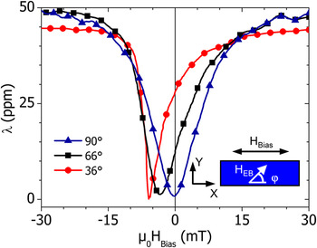
The magnetostrictive strain of exchange biased FeCo layers as a function of an external magnetic field H Bias is presented by Fig. 4. The investigated multilayers consisted of 40 repetitions of the layer sequence Ta 7/Cu 3/Mn70Ir30 7/Fe50Co50 20 [thickness in nm]. The unidirectional anisotropy introduced by the exchange coupling between MnIr and FeCo was established for various angles φ = 36°, 66°, and 90° (φ denotes the angle between H EB and the long cantilever axis, see inset of Fig. 4). For φ = 90°, magnetic anisotropy and unidirectional anisotropy are perpendicular to H Bias. As a result, a symmetrical magnetostriction curve is recorded. The λ(H Bias)-behavior resembles that of a single magnetostrictive material with a magnetic anisotropy aligned in y-direction. The piezomagnetic coefficient, i.e., the derivative of the magnetostriction vanishes at H Bias = 0. With increasing inclination of the unidirectional anisotropy (decreasing φ), the asymmetry of the magnetostriction curves becomes more pronounced and minimum strain is measured at increasing absolute values of H Bias. The tilted orientation of the unidirectional anisotropy causes a deviation of the FeCo magnetization from the y-direction for zero magnetic field. Consequently, the derivative of the magnetization dependent magnetostriction is nonzero. For this particular multilayer, a maximum piezomagnetic coefficient d m = 0.46 ppm/Oe is observed for φ ≈ 66° and H Bias = 0. Further investigation of the ME response as a function of the angle γ between H AC and H EB (γ = 0° in Fig. 4) revealed a more general property. Reference Jahns, Piorra, Lage, Kirchhof, Meyners, Gugat, Krantz, Gerken, Knöchel and Quandt31 Under zero bias field condition, the response is at its maximum for φ = 45°, when the condition γ = 90° is satisfied. Using this finding, vector field sensors can be fabricated. Reference Lage, Woltering, Quandt and Meyners32
Magnetostriction λ as a function of an externally applied magnetic field H Bias. The values for λ were calculated from the measured magnetoelastic coupling coefficient according to λ = −b(1 + νf)(1/E f). Reference Kolkholm30 Here, νf = 0.3 and E f = 230 GPa denote the effective Poisson ratio and Young modulus of the FeCo layer system. Every 70th data point is represented by a symbol. The inset specifies the sample set-up including the definition of angle φ. Adapted from Ref. Reference Lage, Kirchhof, Hrkac, Kienle, Jahns, Knöchel, Quandt and Meyners5.

The concept of exchange biased magnetostrictors can be transferred to multilayers based on the amorphous FeCoSiB alloy. The best LOD at zero bias magnetic field achieved so far equals LOD = 10 pT/(Hz)1/2 at mechanical resonance. The properties of sensors discussed up to this point are summarized in Table II.
Limit of detection for thin film magnetoelectric cantilever sensors operated in mechanical resonance.

C. Frequency conversion technique
In the preceding sections, it was demonstrated that Si bulk micromachined ME heterostructures based on a thin film approach for the functional phases have the potential to detect alternating magnetic fields as small as a few pT. Especially, a tuning fork-like assembly of ME cantilevers is a promising candidate for magnetic field sensor applications. However, exploiting the resonant properties of the cantilever structures results in narrow bandwidth sensors with maximum sensitivity around the mechanical resonance frequency, which is typically in the order of several hundred Hz up to several kHz. On the other hand, many applications such as biomedical ones require high sensitivity and low LOD for frequencies down to a few Hz. Advanced medical applications such as magnetoencephalography and magnetocardiography require highly sensitive DC magnetometers, so far making the utilization of SQUIDs inevitable. In the recent past, considerable progress has been made in enhancing the sensitivity of ME sensors to low frequency and DC magnetic fields. Using a ME nanoelectromechanical resonator, a limit of detection of DC magnetic fields of about 300 pT has been demonstrated. Reference Nan, Hui, Rinaldi and Sun2 High sensitivity to DC magnetic fields has also been reported for a ME microcantilever. Reference Lee, Kim, Yoo, Han, Chun, Kim, Kim, Hwang, Kim, Jo, Kim, Song and Lee4 Such a microcantilever incorporates magnetostrictive Terfenol-D and PZT and is driven off-resonance through a 60 Hz AC magnetic field. An alternative route to high magnetic field sensitivity at low frequency is the frequency conversion technique. This technique is based on applying either magnetic or electric excitation fields. Reference Jahns, Greve, Woltermann, Quandt and Knöchel15,Reference Zhuang, Sing, Dolabdjian, Wang, Finkel, Li and Viehland33–Reference Hayes, Salzer, Reermann, Yarar, Röbisch, Piorra, Meyners, Höft, Knöchel, Schmidt and Quandt35
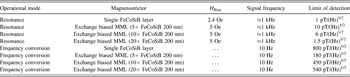
During magnetic frequency conversion, a sinusoidal magnetic modulation field H mod is applied to the sensor. The sensor is driven along its magnetostriction curve (see Fig. 4, φ = 90° case), leading to a modulation of the piezomagnetic coefficient and sensor sensitivity periodic in time. Due to the nonlinearity of the magnetostriction, the sensor acts as a frequency mixing component. If an alternating magnetic field is also present, the sensor voltage output will contain new frequency components such as f ± = f mod ± f AC. By adjusting f mod so that either the sum frequency or difference frequency matches the resonance frequency, resonant enhancement of the ME voltage output is achieved. Thus, the frequency conversion technique increases the sensitivity to alternating magnetic fields having frequencies other than f res. Moreover, sweeping f mod can be used to broaden the effective bandwidth for periodic signals. In Table III LODs are compared for ME cantilevers exposed to magnetic signals with frequencies either matching the resonance frequencies or adjusted to 10 Hz. The magnetostrictive phase is a single 3 µm thick FeCoSiB layer or an exchange biased multilayer. Using the single magnetostrictive layer type sensor, the minimum detectable magnetic field equals 800 pT/(Hz)1/2 for a 10 Hz signal. Thus, the LOD is increased by a factor of 800 compared to that for a resonant alternating magnetic field. Such a large increase cannot be solely explained by losses due to signal conversion into other frequencies than f res. Thus, additional effects are present worsening the LOD for low frequency fields. A major difference exists between the resonant operation and the frequency conversion method in the presence of the modulation field, which is several orders of magnitude larger than the alternating magnetic field to be measured. Noise measurements confirmed that the noise voltage density increases when H mod is applied. Reference Röbisch, Yarar, Urs, Teliban, Knöchel, McCord, Quandt and Meyners20 This suggests that contributions related to the periodic magnetization reversal of the magnetostrictive layer add to the total noise level, thereby worsening the achievable LOD. This explanation is reinforced by the observation of the performance of exchange biased magnetostrictive type sensors (Table III). Since these sensors were fabricated for frequency conversion, the exchange bias direction was established by field cooling with an angle φ = 90°. In resonance, the LOD = 10 pT/(Hz)1/2 is one order of magnitude larger as for the single layer magnetostrictive type. This is attributed to the three times lower total magnetostrictive thickness and the additional unidirectional anisotropy contribution changing the magnetic response characteristics. Increasing the number of repetitions of layer sequences from 5 to 20 improves the LOD for resonant magnetic fields significantly. By contrast, the LOD at 10 Hz reveals a reverse thickness dependency. The best limit of detection [180 pT/(Hz)1/2] for the low frequency field is discovered for sensors having only 5 layer repetitions. At such a low total layer thickness, the additional uniaxial anisotropy imposed by the exchange coupling changes the magnetization reversal, which is accompanied by a lower level of the magnetic noise. Reference Röbisch, Yarar, Urs, Teliban, Knöchel, McCord, Quandt and Meyners20 Upscaling of the total magnetostrictive volume gives rise to an increased demagnetizing field effect, leading to the formation of magnetic domains in the exchange biased layers. Accordingly, domain wall nucleation, movement, and annihilation cause magnetic noise again. In addition, domain wall induced effects can lead to a reduction of the ME response. Reference Urs, Teliban, Piorra, Knöchel, Quandt and McCord36
Limit of detection at selected signal frequencies for thin film magnetoelectric cantilever sensors.

D. Magnetoelectric cantilever sensors for the detection of magnetic fields in medicine
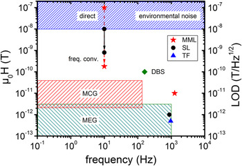
Recently, a first demonstration of ME sensors in a biomedical application succeeded. A bulk laminated ME composite was effectively utilized as susceptometer for a quantitative measurement of iron concentration in liver phantoms. Reference Xi, Qian, Lu, Mei, Rupprecht, Yang and Zhang37 The diagram in Fig. 5 compares typical signal amplitudes in challenging biomedical applications such as magnetocardiography (MCG), magnetoencephalography (MEG), and deep brain stimulation (DBS) 38 to the LODs reported here. In general, MCG and MEG signals measured by SQUID based magnetometers are four to six orders of magnitude smaller than the environmental magnetic noise. In MCG, the signal amplitudes stemming from the beating heart range from 1 pT to roughly 100 pT in a frequency range between fractions of Hz and 100 Hz. Recording of brain signals is even more challenging as the signal amplitudes can be as small as 10 fT. The α-rhythm, one of the strongest brain signals, generates magnetic fields in the order of 10 pT at maximum. Compared to heart signals, the frequency range of brain activity is broader and frequencies up to about 1 kHz can be present.
Amplitude and frequency range of MCG, MEG, and DBS signals in time domain. Reference Sternickel and Braginski39–Reference Wikswo41 Detection limits of magnetoelectric cantilever sensors based on single magnetostrictive layers (exchange biased magnetostrictive multilayers) are represented by black circles (red asterisks). The LOD of the tuning fork-like assembly is indicated by a blue triangle. The direct measurement of the 10 Hz signals was conducted using an integration time equal to 3 s.

A comparison of the displayed data must take into account that the signal amplitudes of the biomagnetic applications specify signals in time domain. Accordingly, recording of MCG and MEG signals requires detection limits being roughly one order of magnitude lower than the respective amplitudes. On the other hand, the sensor to signal source separation must be considered. Especially for signal sources located close to the surface of the human body, the smaller separation achievable with miniaturized uncooled sensors can lead to a significant enhancement of signal amplitudes by more than one order of magnitude at the sensor location. This has been demonstrated by means of magneto-impedance sensors and miniaturized optically pumped atomic magnetometers, which were successfully applied to magnetoencephalographic and magnetocardiographic measurements. Reference Wang, Tajima, Song, Hamada, Cai and Uchiyama42–Reference Alem, Sander, Mhaskar, LeBlanc, Eswaran, Steinhoff, Okada, Kitching, Trahms and Knappe45 From Fig. 5 it becomes evident that frequency conversion applied to ME heterostructures is a promising candidate for gaining access to the low frequency biomagnetic signals, too. At 10 Hz, the LOD = 180 pT/(Hz)1/2 of ME sensors with exchange biased magnetostrictive multilayers is only a small factor above the upper MCG signal limit. From the data in Table III and the discussion in Sec. III. C, it can be concluded that further improvements are possible. If a rise of the effective in plane demagnetization field can be avoided, increasing the total magnetostrictive layer thickness will push the detection limit further downwards.
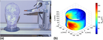
The detection limit of resonant ME cantilever sensors reaches the upper frequency limit of MEG signals. A reduction of the resonance frequency can be simply achieved by changing the sensor design. However, it is not considered to be a sufficient measure for enabling the detection of MEG signals with lower frequencies due to an increase of the 1/f dependent noise level. In fact, resonant ME sensors are envisaged for the application in deep brain stimulation. DBS is an established therapy for Parkinson’s disease. Reference Schuepbach, Rau, Knudsen, Volkmann, Krack, Timmermann, Hälbig, Hesekamp, Navarro, Meier, Falk, Mehdorn, Paschen, Maarouf, Barbe, Fink, Kupsch, Gruber, Schneider, Seigneuret, Kistner, Chaynes, Ory-Magne, Brefel Courbon, Vesper, Schnitzler, Wojtecki, Houeto, Bataille, Maltête, Damier, Raoul, Sixel-Doering, Hellwig, Gharabaghi, Krüger, Pinsker, Amtage, Régis, Witjas, Thobois, Mertens, Kloss, Hartmann, Oertel, Post, Speelman, Agid, Schade-Brittinger and Deuschl46,Reference Deuschl and Agid47 Small electrodes are implanted in intracerebral nuclei for the electrical stimulation with the aim to influence brain circuits. For example, DBS of the thalamus can efficiently reduce tremor. Such a desired clinical effect depends on the electrode position and the stimulated current distribution in the brain of patients with their individual anatomy. Clinical applicability and understanding of DBS would benefit from an uncomplicated measurement technique identifying the area of the brain that is stimulated. Since the electrodes are operated at a fixed frequency ranging from 85 Hz to 185 Hz, 38 a direct measurement of higher harmonics appears to be feasible by resonant ME cantilever sensors with single layer magnetostrictors or a tuning fork-like assembly of cantilever sensors. First test measurements using a head phantom and a ME sensor scanning the flux density distribution generated by a DBS electrode are shown in Fig. 6. During this first trial, the electrode was supplied with DBS pulses with a larger amplitude than the pulses applied in clinical practice. The pulse frequency was 160 Hz and its fifth harmonic was recorded.
(a) Photograph of a pneumatic scanner with head phantom and inserted DBS electrode. The ME sensor is surrounded by a copper coil to supply a static bias field. During scanner operation the sensor is moved around the phantom on a cylindrical surface. The phantom is a glass head filled with saline solution. The solution’s conductivity matches that of a human brain. (b) Plot of the magnetic flux distribution (radial component) surrounding the head phantom, recorded by the ME sensor while operating the DBS electrode.

IV. CONCLUSIONS
In summary, the high potential of bulk micromachined magnetoelectric cantilever sensors for magnetic field sensing applications is demonstrated. The achievable limit of detection can be significantly improved by magnetoelectric voltage enhancement through mechanical resonance, frequency conversion and noise level reduction of exchange biased magnetostrictive multilayers. For alternating magnetic fields matching the mechanical resonance, the detection limit is in the order of 1 pT/(Hz)1/2. Using frequency conversion, the best LOD achieved so far equals 180 pT/(Hz)1/2 at 10 Hz. First biomagnetic applications such as the measurement of current density distributions in the human brain induced by deep brain stimulation are in reach. A combination of the enhancement concepts mentioned above will further improve the performance of magnetoelectric sensors. Other potential methods such as the reduction of substrate clamping effects, the use of more sophisticated resonator structures and sensor arrays, as well as applying sensors based on a magnetically induced change of the elastic properties Reference Zabel, Kirchhof, Yarar, Meyners, Quandt and Faupel18 were not discussed within this article.
Supplementary Material
To view supplementary material for this article, please visit https://doi.org/10.1557/jmr.2017.58.
ACKNOWLEDGMENTS
The authors would like to thank the German Research Foundation DFG for financial support through the Collaborative Research Center SFB 855 ‘Magnetoelectric composites—future biomagnetic interfaces’ and the Grant PAK 902. The authors acknowledge the permission to reproduce article extracts provided by Nature Publishing Group, Elsevier, AIP Publishing LLC and IEEE.