





1 Introduction
Interactions of high-power, short-pulse lasers with matter can generate relativistic electrons[ Reference Esarey, Schroeder and Leemans 1 – Reference Faure, Glinec, Pukhov, Kiselev, Gordienko, Lefebvre, Rousseau, Burgy and Malka 3 ], intense ion beams[ Reference Macchi, Borghesi and Passoni 4 – Reference Daido, Nishiuchi and Pirozhkov 6 ], neutrons[ Reference Yogo, Lan, Arikawa, Abe, Mirfayzi, Wei, Mori, Golovin, Hayakawa, Iwata, Fujioka, Nakai, Sentoku, Mima, Murakami, Koizumi, Ito, Lee, Takahashi, Hironaka, Kar, Nishimura and Kodama 7 – Reference Vallières, Fillion-Gourdeau, Fourmaux, Poupart-Raîche, Dietrich, Beier, Lelièvre, Catrix, Maltais, Hussein, Antici, Légaré and MacLean 9 ], photons[ Reference Corde, Phuoc, Lambert, Fitour, Malka, Rousse, Beck and Lefebvre 10 – Reference Günther, Rosmej, Tavana, Gyrdymov, Skobliakov, Kantsyrev, Zähter, Borisenko, Pukhov and Andreev 12 ] and strong transient electromagnetic signals[ Reference Consoli, Tikhonchuk, Bardon, Bradford, Carroll, Cikhardt, Cipriani, Clarke, Cowan, Danson, De Angelis, De Marco, Dubois, Etchessahar, Garcia, Hillier, Honsa, Jiang, Kmetik, Krása, Li, Lubrano, McKenna, Metzkes-Ng, Poyé, Rączka, Smith, Vrana, Woolsey, Zemaityte, Zhang, Zhang, Zielbauer and Neely 13 – Reference He, Wang, Deng, Feng, Xia, Hu, Zhu, Xie, Yuan, Zhang, Lu, Yang, Cheng, Li, Yan, Fang, Li, Zhou, Li, Chen, Lin and Yan 15 ], making them an important platform for studies of high-energy-density physics[ Reference Sakata, Lee, Johzaki, Sawada, Iwasa, Morita, Matsuo, Law, Yao, Hata, Sunahara, Kojima, Abe, Kishimoto, Syuhada, Shiroto, Morace, Yogo, Iwata, Nakai, Sakagami, Ozaki, Yamanoi, Norimatsu, Nakata, Tokita, Miyanaga, Kawanaka, Shiraga, Mima, Nishimura, Bailly-Grandvaux, Santos, Nagatomo, Azechi, Kodama, Arikawa, Sentoku and Fujioka 16 – Reference Sawada, Yabuuchi, Higashi, Iwasaki, Kawasaki, Maeda, Izumi, Nakagawa, Shigemori, Sakawa, Curry, Frost, Iwata, Ogitsu, Sueda, Togashi, Hu, Glenzer, Kemp, Ping and Sentoku 18 ], laboratory astrophysics[ Reference Remington, Drake and Ryutov 19 – Reference Li, Tzeferacos, Lamb, Gregori, Norreys, Rosenberg, Follett, Froula, Koenig, Seguin, Frenje, Rinderknecht, Sio, Zylstra, Petrasso, Amendt, Park, Remington, Ryutov, Wilks, Betti, Frank, Hu, Sangster, Hartigan, Drake, Kuranz, Lebedev and Woolsey 21 ], fast ignition[ Reference Tabak, Hammer, Glinsky, Kruer, Wilks, Woodworth, Campbell, Perry and Mason 22 – Reference Gong, Habara, Sumioka, Yoshimoto, Hayashi, Kawazu, Otsuki, Matsumoto, Minami, Abe, Aizawa, Enmei, Fujita, Ikegami, Makiyama, Okazaki, Okida, Tsukamoto, Arikawa, Fujioka, Iwasa, Lee, Nagatomo, Shiraga, Yamanoi, Wei and Tanaka 24 ], irradiation diagnostics[ Reference Schaeffer, Bott, Borghesi, Flippo, Fox, Fuchs, Li, Park, Seguin, Tzeferacos and Willingale 25 – Reference Zhou, Fang, Chen, Wu, Du, Yan, Tang and Huang 27 ] and compact secondary sources. Laser peak intensity is a key parameter governing the performance of particle and radiation sources. Equally important, however, are the efficiency of laser–electron coupling and the subsequent transfer of energy into the processes responsible for secondary particle and radiation generation. Improving laser–plasma coupling efficiency is therefore a key route to achieving high-performance laser-driven particle and radiation sources[ Reference Kemp, Sentoku and Tabak 28 ].
The physics of interactions of relativistic laser pulses with solid targets over timescales ranging from sub-picoseconds to multi-picoseconds differs substantially from that of femtosecond irradiation of a steep overdense interface. On the picosecond timescale, the front-side preplasma no longer behaves as a quasi-static, steep boundary, but instead undergoes strongly time-dependent evolution, including hole boring, front-surface steepening, plasma expansion, electron refluxing and the buildup of self-generated electromagnetic fields[ Reference Kemp, Sentoku and Tabak 28 – Reference Iwata, Sentoku, Sano and Mima 35 ]. As a result, electron acceleration in picosecond laser–solid interactions often deviates from simple ponderomotive scaling, enabling the generation of super-ponderomotive electrons. This behavior strongly affects rear-side sheath formation, ion acceleration and the production of secondary particles and radiation[ Reference Kemp and Divol 29 – Reference Simpson, Scott, Mariscal, Rusby, King, Grace, Aghedo, Pagano, Sinclair, Armstrong, Manuel, Haid, Flippo, Winslow, Gatu-Johnson, Frenje, Neely, Kerr, Williams, Andrews, Cauble, Charron, Costa, Fischer, Maricle, Stuart, Albert, Lemos, MacKinnon, MacPhee, Pak and Ma 38 ]. Previous experimental and theoretical studies have shown that multi-picosecond relativistic laser pulses can substantially enhance fast electron[ Reference Sorokovikova, Arefiev, McGuffey, Qiao, Robinson, Wei, McLean and Beg 30 , Reference Iwata, Sentoku, Sano and Mima 35 – Reference Weichman, Robinson, Beg and Arefiev 37 ] and proton[ Reference Yogo, Mima, Iwata, Tosaki, Morace, Arikawa, Fujioka, Johzaki, Sentoku, Nishimura, Sagisaka, Matsuo, Kamitsukasa, Kojima, Nagatomo, Nakai, Shiraga, Murakami, Tokita, Kawanaka, Miyanaga, Yamanoi, Norimatsu, Sakagami, Bulanov, Kondo and Azechi 31 , Reference Iwata, Mima, Sentoku, Yogo, Nagatomo, Nishimura and Azechi 32 , Reference Kim, Kemp, Wilks, Kalantar, Kerr, Mariscal, Beg, McGuffey and Ma 34 , Reference Simpson, Scott, Mariscal, Rusby, King, Grace, Aghedo, Pagano, Sinclair, Armstrong, Manuel, Haid, Flippo, Winslow, Gatu-Johnson, Frenje, Neely, Kerr, Williams, Andrews, Cauble, Charron, Costa, Fischer, Maricle, Stuart, Albert, Lemos, MacKinnon, MacPhee, Pak and Ma 38 ] production, underscoring the key role of plasma evolution in intense laser–solid interactions. When an underdense or near-critical-density plasma region with an appropriate scale length forms in front of the target, electron acceleration can be markedly improved. Under such conditions, the laser can propagate over an extended distance in the low-density plasma, form a plasma channel and efficiently accelerate electrons through mechanisms such as direct laser acceleration (DLA)[ Reference Pukhov, Sheng and Meyer-ter-Vehn 39 – Reference Huang, Robinson, Zhou, Qiao, Liu, Ruan, He and Norreys 42 ]. Significant increases in electron energy, beam charge and photon yield have been reported in systems involving pre-expanded target plumes[ Reference Hussein, Arefiev, Batson, Chen, Craxton, Davies, Froula, Gong, Haberberger, Ma, Nilson, Theobald, Wang, Weichman, Williams and Willingale 43 , Reference Willingale, Thomas, Nilson, Chen, Cobble, Craxton, Maksimchuk, Norreys, Sangster, Scott, Stoeckl, Zulick and Krushelnick 44 ], long-scale-length near-critical-density plasmas and preheated low-density foams[ Reference Rosmej, Andreev, Zaehter, Zahn, Christ, Borm, Radon, Sokolov, Pugachev, Khaghani, Horst, Borisenko, Sklizkov and Pimenov 45 – Reference Scott, Beaucourt, Schlenvoigt, Markey, Lancaster, Ridgers, Brenner, Pasley, Gray, Musgrave, Robinson, Li, Notley, Davies, Baton, Santos, Feugeas, Nicolaï, Malka, Tikhonchuk, McKenna, Neely, Rose and Norreys 48 ]. Taken together, these results suggest that effective control of the low-density plasma distribution in front of the target is an important route to enhancing laser-energy coupling to particle and radiation sources.
Existing experimental studies have focused mainly on interactions of single picosecond laser pulses with solid targets[ Reference Kemp and Divol 29 , Reference Sorokovikova, Arefiev, McGuffey, Qiao, Robinson, Wei, McLean and Beg 30 ], or on externally preconditioned targets produced by low-intensity nanosecond laser ablation[ Reference Hussein, Arefiev, Batson, Chen, Craxton, Davies, Froula, Gong, Haberberger, Ma, Nilson, Theobald, Wang, Weichman, Williams and Willingale 43 , Reference Willingale, Thomas, Nilson, Chen, Cobble, Craxton, Maksimchuk, Norreys, Sangster, Scott, Stoeckl, Zulick and Krushelnick 44 ] or the use of low-density foams[ Reference Rosmej, Andreev, Zaehter, Zahn, Christ, Borm, Radon, Sokolov, Pugachev, Khaghani, Horst, Borisenko, Sklizkov and Pimenov 45 – Reference Rosmej, Gyrdymov, Andreev, Tavana, Popov, Borisenko, Gromov, Gus’kov, Yakhin, Vegunova, Bukharskii, Korneev, Cikhardt, Zähter, Busch, Jacoby, Pimenov, Spielmann and Pukhov 47 ]. By contrast, two independently controlled petawatt-class picosecond laser pulses incident on planar targets with an adjustable temporal delay are expected to provide a means of actively manipulating the preplasma evolution in front of the target, thereby modifying the coupled response of fast electrons, sheath-accelerated ions, neutrons and electromagnetic pulses (EMPs)[ Reference Scott, Beaucourt, Schlenvoigt, Markey, Lancaster, Ridgers, Brenner, Pasley, Gray, Musgrave, Robinson, Li, Notley, Davies, Baton, Santos, Feugeas, Nicolaï, Malka, Tikhonchuk, McKenna, Neely, Rose and Norreys 48 – Reference Yao, Nakatsutsumi, Buffechoux, Antici, Borghesi, Ciardi, Chen, d’Humières, Gremillet, Heathcote, Horný, McKenna, Quinn, Romagnani, Royle, Sarri, Sentoku, Schlenvoigt, Toncian, Tresca, Vassura, Willi and Fuchs 52 ]. Experimental evidence for such a configuration, however, remains limited. The significance of dual-pulse irradiation of solid targets lies not simply in increasing the total incident energy, but more importantly in introducing an additional degree of freedom for controlling the plasma conditions encountered by the subsequent pulse. As a result, the interaction dynamics and coupling pathway can be modified[ Reference Corde, Phuoc, Lambert, Fitour, Malka, Rousse, Beck and Lefebvre 10 , Reference Rosmej, Gyrdymov, Günther, Andreev, Tavana, Neumayer, Zähter, Zahn, Popov, Borisenko, Kantsyrev, Skobliakov, Panyushkin, Bogdanov, Consoli, Shen and Pukhov 17 , Reference Lebedev, Frank and Ryutov 20 , Reference Iwata, Kojima, Sentoku, Hata and Mima 33 – Reference Simpson, Scott, Mariscal, Rusby, King, Grace, Aghedo, Pagano, Sinclair, Armstrong, Manuel, Haid, Flippo, Winslow, Gatu-Johnson, Frenje, Neely, Kerr, Williams, Andrews, Cauble, Charron, Costa, Fischer, Maricle, Stuart, Albert, Lemos, MacKinnon, MacPhee, Pak and Ma 38 ].
The recent upgrade of the SG-II Upgrade facility has provided a unique opportunity to investigate this problem under realistic large-facility conditions[ Reference Zhu, Zhu, Li, Zhu, Ma, Lu, Fan, Liu, Zhou, Xu, Zhang, Xie, Yang, Wang, Ouyang, Wang, Li, Yang, Fan, Sun, Liu, Liu, Zhang, Tao, Sun, Zhu, Wang, Jiao, Ren, Liu, Jiao, Huang and Lin 53 , Reference Li, Chen, Chen, Liu, Gu, Guo, Hua, Huang, Leng, Li, Li, Li, Lin, Lu, Lyu, Ma, Ning, Peng, Wan, Wang, Wang, Wei, Yan, Zhang, Zhao, Zhao, Zhou, Zhou, Zhou, Zhu and Zhu 54 ]. Following the 2024 upgrade, the facility can deliver 16 nanosecond laser beams and two synchronized picosecond laser beams, enabling the coordinated operation of two independently controlled kilojoule-class picosecond petawatt pulses[ Reference Li, Chen, Chen, Liu, Gu, Guo, Hua, Huang, Leng, Li, Li, Li, Lin, Lu, Lyu, Ma, Ning, Peng, Wan, Wang, Wang, Wei, Yan, Zhang, Zhao, Zhao, Zhou, Zhou, Zhou, Zhu and Zhu 54 ]. This capability enables controlled experimental studies of dual-pulse interactions with planar foil targets beyond conventional single-beam multi-picosecond laser–solid configurations. In particular, it enables systematic investigation of the reshaping of the low-density plasma environment in front of the target by the leading picosecond pulse, and of the enhanced coupling of the delayed second pulse to this actively tailored preplasma.
Motivated by this opportunity, we carried out combined experimental and numerical studies of dual petawatt-class picosecond laser pulses interacting with planar metal foil targets. Compared with previous dual-pulse and multi-pulse laser–solid studies, which mainly focused on fast-electron collimation or guiding by self-generated magnetic fields[ Reference Scott, Beaucourt, Schlenvoigt, Markey, Lancaster, Ridgers, Brenner, Pasley, Gray, Musgrave, Robinson, Li, Notley, Davies, Baton, Santos, Feugeas, Nicolaï, Malka, Tikhonchuk, McKenna, Neely, Rose and Norreys 48 , Reference Volpe, Feugeas, Nicolaï, Santos, Touati, Breil, Batani and Tikhonchuk 50 , Reference Malko, Vaisseau, Perez, Batani, Curcio, Ehret, Honrubia, Jakubowska, Morace, Santos and Volpe 51 ], proton-acceleration optimization using double-pulse temporal envelopes[ Reference Markey, McKenna, Brenner, Carroll, Günther, Harres, Kar, Lancaster, Nürnberg, Quinn, Robinson, Roth, Zepf and Neely 49 , Reference Brenner, Robinson, Markey, Scott, Gray, Rosinski, Deppert, Badziak, Batani, Davies, Hassan, Lancaster, Li, Musgrave, Norreys, Pasley, Roth, Schlenvoigt, Spindloe, Tatarakis, Winstone, Wolowski, Wyatt, McKenna and Neely 55 ] or multiplexed-beam coupling in preformed large-scale plasmas[ Reference Yao, Nakatsutsumi, Buffechoux, Antici, Borghesi, Ciardi, Chen, d’Humières, Gremillet, Heathcote, Horný, McKenna, Quinn, Romagnani, Royle, Sarri, Sentoku, Schlenvoigt, Toncian, Tresca, Vassura, Willi and Fuchs 52 ], the present work addresses a different response of the laser–foil system. Here, the first pulse actively reshapes the front-side low-density plasma environment, and the delayed second pulse subsequently couples to this self-generated plasma, leading to enhanced high-energy electron production through DLA. Experimentally, dual-pulse irradiation is associated with a pronounced hardening of the electron spectrum, together with increases in the peak EMP amplitude and neutron yield. The simulations further suggest that the enhanced coupling of the delayed pulse to the front-side plasma layer is responsible for the strengthened electron acceleration. Together, the experimental and numerical results suggest a route to controlling multiple secondary-source signatures through temporal control of the laser–foil coupling environment.
The remainder of this paper is organized as follows. Section 2 describes the experimental setup and target parameters. Section 3 presents the experimental results for electrons, EMPs and neutrons, together with supporting proton measurements. Section 4 discusses the particle-in-cell (PIC) simulation results and the enhanced laser–target coupling under dual-pulse irradiation. Finally, Section 5 summarizes the main conclusions.
2 Experimental setup
The experiment was carried out at the SG-II Upgrade laser facility, which is capable of delivering two ultra-intense short-pulse beams in a synchronized manner. Each pulse had an energy above
$300\;\mathrm{J}$
 , a full width at half-maximum (FWHM) duration of less than
$2\;\mathrm{ps}$
 and a focal spot diameter of approximately
$30\;\unicode{x3bc} \mathrm{m}$
 . Two planar metal foil targets were used: a 10-μm-thick Au foil and a 20-
$\unicode{x3bc} \mathrm{m}$
 -thick Cu foil. The rear surface of each foil was coated with a nanometer-scale CH layer to enable proton generation. The temporal delay between the two pulses could be continuously adjusted. Both picosecond pulses were focused onto the same spot on the target surface and irradiated the target sequentially with a controlled delay.
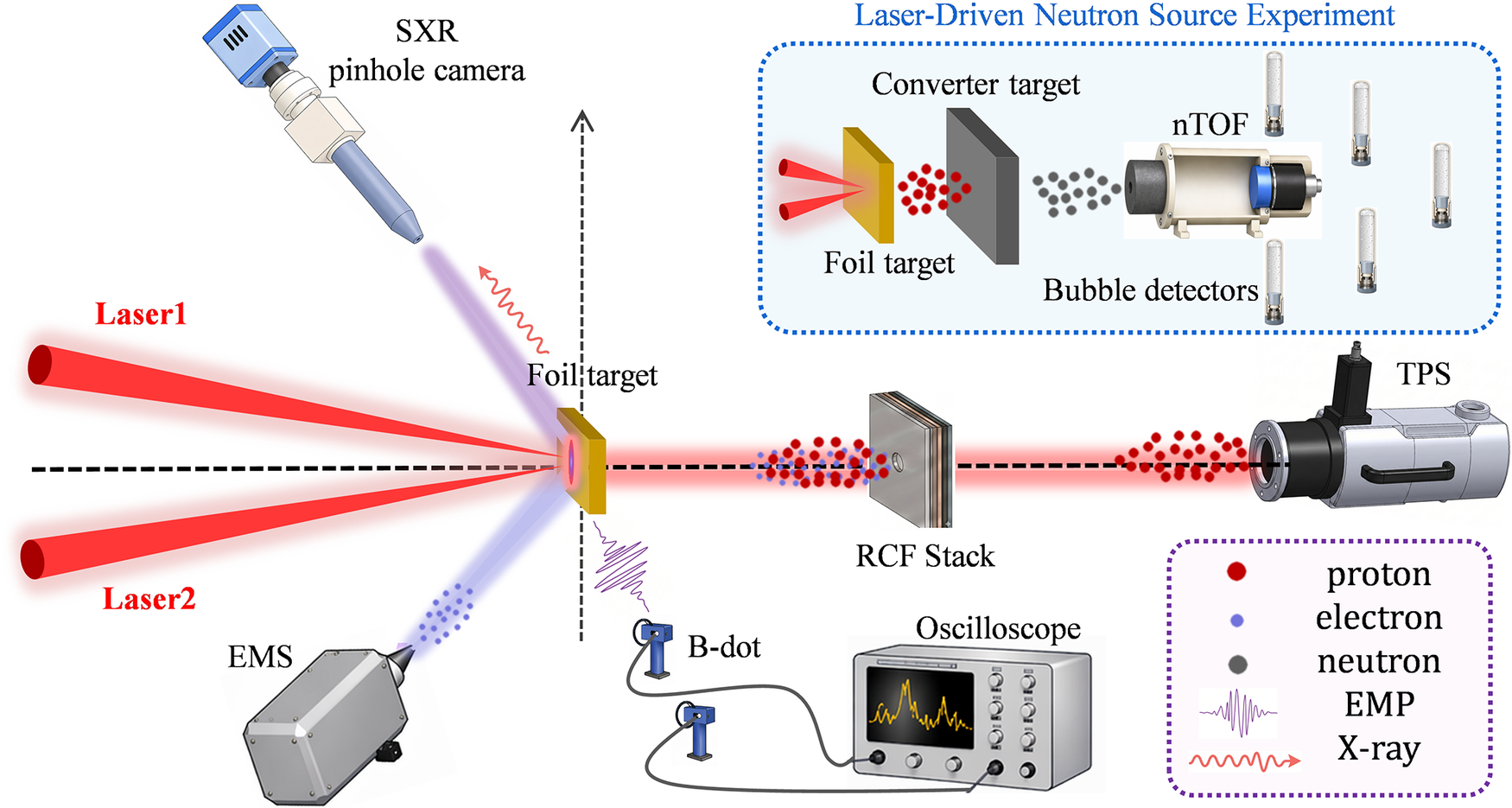
The experimental diagnostic layout is shown in Figure 1. Two picosecond laser beams were focused onto the same spot on the target surface at near-normal incidence. A magnetic spectrometer with a field strength of 4000 G was positioned 45 cm from the target on the lateral side, at an angle of 50° with respect to the target normal, to measure the electron energy spectrum. On the opposite lateral side, viewing the target-front surface, a soft-X-ray pinhole camera was installed 58 cm from the target at 45° to the target normal, with a magnification of 2.1, to record the self-emission from the interaction region. Along the rear target normal, a stack of radiochromic film (RCF) was used to measure the proton energy and angular distributions. A Thomson parabola spectrometer (TPS) was placed along the same direction, 52 cm from the target, to obtain the proton energy spectrum. Two B-dot probes were installed at lateral distances of 60 and 120 cm from the target, with their axes perpendicular to the target normal, and were connected to oscilloscopes outside the chamber through coaxial cables to record EMP signals. For neutron-generation shots, the RCF stack and TPS behind the primary foil target were removed and replaced by a converter target. The converter target was positioned along the rear target normal, with its center aligned with the target normal, at a distance of 1 mm from the rear surface of the primary foil target. Converter targets of different materials and thicknesses were used in different shots, while the transverse dimensions of all converter targets were 1 cm × 1 cm. A neutron time-of-flight (nTOF) spectrometer was positioned behind the converter to measure the neutron energy spectrum, while several bubble detectors distributed around the chamber wall were used to diagnose the neutron angular distribution.
Schematic of the experimental diagnostic layout. Two picosecond (ps) laser beams are focused onto the same spot on a planar foil target. A magnetic spectrometer is positioned 50° with respect to the target normal to measure the electron energy spectrum, while a soft-X-ray pinhole camera is placed on the opposite lateral side to view the target-front surface and record the self-emission from the interaction region. Along the rear target normal, a stack of RCF and a TPS are used to diagnose the proton angular distribution and energy spectrum, respectively. Two B-dot probes, located inside the target chamber and on the chamber wall, respectively, are used to record EMP signals. For neutron-generation experiments, the RCF stack and TPS behind the primary foil are removed and replaced by a converter target. The converter target is placed 1 mm downstream of the primary foil along the rear target normal, with a transverse size of 1 cm × 1 cm. Different converter materials and thicknesses, including 5-mm-thick Tb, 6-mm-thick Nb, 8-mm-thick Ta and 5-mm-thick LiF, are used in the neutron-generation shots. A neutron time-of-flight (nTOF) spectrometer is positioned behind the converter to measure the neutron energy spectrum, while bubble detectors distributed at multiple locations on the chamber wall are used to diagnose the neutron angular distribution.

Figure 1 Long description
The diagram illustrates an experimental layout centered on a Foil target.
* Input: Two red beams, Laser 1 and Laser 2, converge from the left onto the front surface of the Foil target.
* Lateral Diagnostics: To the top-left, an S X R pinhole camera captures X-ray emission. To the bottom-left, an E M S instrument detects an electron cloud.
* Rear Axis Diagnostics: Along the horizontal dashed line to the right of the target, a red proton beam passes through an R C F Stack and enters a T P S device.
* Electromagnetic Monitoring: Below the target, two B-dot probes are wired to an Oscilloscope displaying a wave signal.
* Neutron Source Inset: A blue-bordered box at the top-right titled Laser-Driven Neutron Source Experiment shows a modified setup where a Converter target is placed behind the Foil target. This generates a grey neutron cloud that is measured by an n T O F spectrometer and five cylindrical Bubble detectors.
* Legend: A purple-bordered box at the bottom-right defines the symbols: red circles for proton, blue circles for electron, grey circles for neutron, a purple wave for E M P, and a red wavy arrow for X-ray.
3 Experimental results
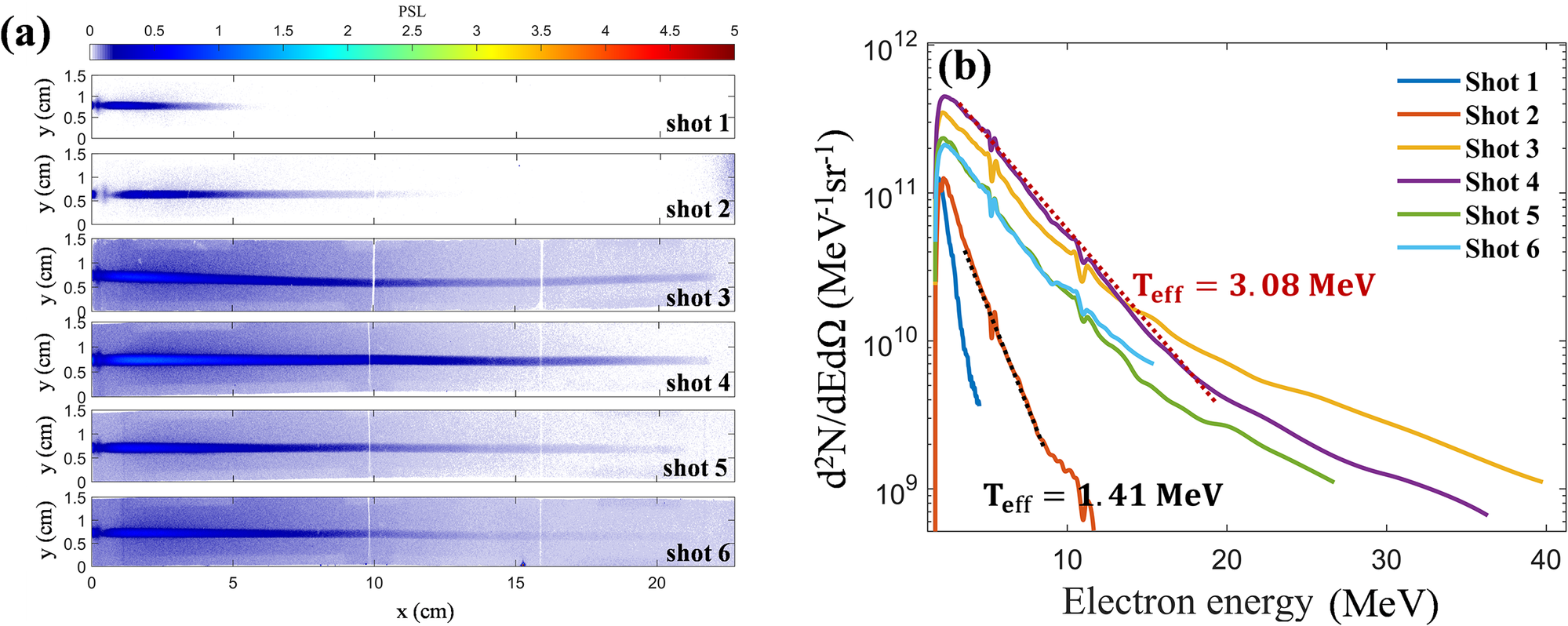
The energy distribution of energetic electrons emitted toward the laser-incident side was measured using a 4000 G magnetic spectrometer over an effective energy range of 3–50 MeV. Six valid shots were obtained in this campaign. The raw imaging-plate data and corresponding spectra are shown in Figure 2, and the laser conditions, target parameters and extracted electron-beam characteristics are summarized in Table 1. Shots 1 and 2 correspond to single-pulse interactions with a 20-
$\unicode{x3bc} \mathrm{m}$
 -thick Cu foil, whereas Shots 3–6 were obtained under dual-pulse conditions. Among them, Shot 2 (single pulse, Cu target) and Shot 4 (dual pulses, Cu target) provide the most direct comparison, while the remaining shots mainly support the overall trend. Within this data set, dual-pulse irradiation is associated with higher electron cutoff energy, larger electron yield and an increase in the effective electron temperature compared with the single-pulse cases.
Electron energy distribution. (a) Raw electron signals recorded on the imaging plate of the magnetic spectrometer for six valid shots. Shots 1 and 2 correspond to single-pulse irradiation, whereas Shots 3–6 correspond to dual-pulse irradiation. (b) Electron energy spectra reconstructed from the imaging-plate signals recorded by the magnetic spectrometer. The effective electron temperatures extracted from representative spectra, Shot 2 for the single-pulse case and Shot 4 for the dual-pulse case, are indicated in the figure.

Figure 2 Long description
The figure consists of two panels labeled a and b.
Panel a is a vertical stack of six heatmaps representing Shot 1 through Shot 6. Each heatmap has an x-axis from 0 to 20 centimeters and a y-axis from 0 to 1.5 centimeters. A color scale at the top indicates P S L values from 0 to 5, transitioning from white to blue to yellow to red. Shots 1 and 2 show short, concentrated blue streaks. Shots 3 through 6 show significantly longer and more intense blue streaks extending across the full x-axis range.
Panel b is a line graph showing electron energy spectra. The x-axis is Electron energy in M e V ranging from 0 to 40. The y-axis is d super 2 N all over d E d Omega in units of M e V super minus 1 s r super minus 1, ranging from 10 super 9 to 10 super 12 on a logarithmic scale. Six colored lines represent the shots:
* Shot 1 (dark blue) and Shot 2 (orange) show steep declines, ending before 15 M e V. A black dotted line fit for Shot 2 indicates T sub e f f equals 1.41 M e V.
* Shot 3 (yellow), Shot 4 (purple), Shot 5 (green), and Shot 6 (light blue) show higher intensities and more gradual declines extending up to 40 M e V. A red dotted line fit for Shot 4 indicates T sub e f f equals 3.08 M e V.
Experimental laser and target parameters, together with the corresponding electron-beam characteristicsa.

Table 1 Long description
The table consists of 13 columns and 6 data rows.
Columns from left to right are:
1. N sub shot (Shot number 1 to 6).
2. N sub pulses (Single or Dual).
3. Target material (Cu or Au).
4. th / mu m (Target thickness: 10 or 20).
5. E sub l sub 1 / J (Energy of first beam).
6. E sub l sub 2 / J (Energy of second beam).
7. tau sub l sub 1 / ps (Pulse duration of first beam).
8. tau sub l sub 2 / ps (Pulse duration of second beam).
9. t sub D / ps (Temporal delay).
10. Q sub 1 / nC dot sr super minus 1 (Integrated electron charge).
11. Q sub 2 / nC dot sr super minus 1 (Charge above 5 MeV).
12. T sub eff / MeV (Effective electron temperature).
13. E sub max / MeV (Maximum electron energy).
Data Summary:
- Shots 1 and 2 are Single pulse on Cu targets (20 mu m). Q sub 1 values are 17.02 and 36.14 respectively.
- Shots 3 through 6 are Dual pulse shots with a 4 ps delay (t sub D).
- Shot 3 (Au, 10 mu m): E sub l sub 1 = 382 J, E sub l sub 2 = 379 J, Q sub 1 = 241.63, E sub max = 37.2 MeV.
- Shot 4 (Cu, 20 mu m): E sub l sub 1 = 378 J, E sub l sub 2 = 315 J, Q sub 1 = 312.37, E sub max = 33.8 MeV.
- Shot 5 (Au, 10 mu m): E sub l sub 1 = 375 J, E sub l sub 2 = 361 J, Q sub 1 = 136.51, E sub max = 23.6 MeV.
- Shot 6 (Cu, 20 mu m): E sub l sub 1 = 393 J, E sub l sub 2 = 454 J, Q sub 1 = 128.74, E sub max = 24.5 MeV.
For all dual pulse shots, tau sub l sub 2 is listed as less than 2 ps.
a
${E_{\mathrm{l}}}_1$
 and
${E_{\mathrm{l}}}_2$
 are the energies of the first and second picosecond beams, respectively;
${\tau_\mathrm{l}}_1$
 and
${\tau_\mathrm{l}}_2$
 are their FWHM pulse durations; and
${t}_\mathrm{D}$
 is the temporal delay between the two beams at the target. For single-pulse shots,
${E_{\mathrm{l}}}_2$
 ,
${\tau_\mathrm{l}}_2$
 and
${t}_\mathrm{D}$
 are not applicable and are denoted by ‘/’.
${Q}_1$
 is the electron charge per steradian integrated over the measured spectrum,
${Q}_2$
 is the electron charge per steradian for electrons above 5 MeV and
${T}_{\mathrm{eff}}$
 is the effective electron temperature. Shot-resolved values of
${\tau_\mathrm{l}}_2$
 were not available owing to limitations of the on-shot pulse-duration diagnostic;
${\tau_\mathrm{l}}_2$
 is therefore listed as less than 2 ps, consistent with the facility operating condition that each picosecond beam delivered more than 300 J with a pulse duration below 2 ps.
A detailed comparison was made between Shot 2 (single pulse, Cu target) and Shot 4 (dual pulses, Cu target), which serves as the clearest matched comparison and the main direct experimental basis for the conclusions of this work. In Shot 4, the two pulses were separated by a delay of
$4\;\mathrm{ps}$
 , with the second pulse arriving
$4\;\mathrm{ps}$
 after the first pulse, and the total laser energy was 693 J, approximately twice that of Shot 2 (336 J). The experimental results show that the electron cutoff energy increased from 9.3 MeV in Shot 2 to 33.8 MeV in Shot 4, corresponding to an enhancement factor of approximately 3.6. The total electron yield per steradian increased by a factor of 8.64, while the charge of electrons above 5 MeV increased by a factor of 30.22. The electron spectrum in Shot 4 also shows a harder high-energy tail and a higher effective electron temperature than that in Shot 2. Under the present experimental conditions, this matched comparison provides the clearest direct experimental indication that dual-pulse irradiation is associated with substantially enhanced high-energy electron generation.
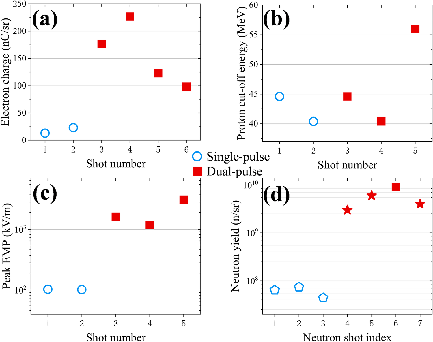
The most direct experimental evidence for enhanced laser–target coupling under dual-pulse irradiation comes from the electron measurements. As shown in Figure 3(a), the electron charge per steradian is systematically higher under dual-pulse conditions than under single-pulse conditions. The data points correspond to different shots, with open blue circles representing single-pulse irradiation and solid red squares representing dual-pulse irradiation. Figures 3(b)–3(d) show the corresponding proton cutoff energy, peak EMP amplitude and neutron yield, respectively. These observables were obtained using different diagnostics: the electron charge per steradian and electron cutoff energy were extracted from the spectra measured by the front-side magnetic spectrometer; the proton cutoff energy was determined by combining measurements from the TPS and the RCF stack; the peak EMP amplitude was recorded by the B-dot probes; and the neutron yield was inferred from the bubble detectors. The EMP data from the present electron/proton shots also show higher peak amplitudes under dual-pulse irradiation. The neutron data, obtained in the separate neutron-generation configuration described below, show higher yields under comparable dual-pulse conditions. Compared with the single-pulse case, the peak EMP amplitude increases by approximately 10–30 times, while the neutron yield increases by factors of tens, approaching two orders of magnitude in the largest case. By contrast, the measured proton cutoff energy does not show a clear enhancement under the present dual-pulse conditions. Therefore, although the electron spectra provide the primary evidence for enhanced laser–target coupling in the matched comparison, the EMP and neutron measurements provide complementary evidence for a correlated secondary-source response under dual-pulse driving.
Experimental results for particles and electromagnetic pulses. Panels (a)–(d) show the measured electron charge per steradian, proton cutoff energy, peak electromagnetic pulse (EMP) amplitude and neutron yield per steradian, respectively. In panels (a)–(c), open blue circles denote single-pulse conditions, whereas solid red squares denote dual-pulse conditions. For Shot 6, no valid EMP diagnostic data were available owing to diagnostic limitations. In panel (d), open blue pentagons denote single-pulse conditions, and solid red stars denote dual-pulse conditions. The neutron-yield data in panel (d) should not be interpreted as having a one-to-one correspondence with the shot numbers listed in Table 1, because proton diagnostics and the neutron-generation configuration could not be fielded simultaneously in the same shot. In the neutron-generation shots, the RCF stack and TPS used for proton diagnostics were replaced by a converter target. Among the dual-pulse neutron-yield data, only the point labeled Shot 6 corresponds to Shot 6 in Table 1, which is shown by the solid red square in panel (d). The single-pulse neutron-yield data were obtained from an independent single-pulse experimental campaign at the SG-II Upgrade facility and are used as reference data under comparable laser conditions, as indicated by the open blue pentagons in panel (d). The other three dual-pulse neutron-yield data points were obtained from additional neutron-generation shots in the present campaign, as indicated by the solid red stars in panel (d). These shots had laser parameters comparable to those of Shots 3–6 but were not accompanied by simultaneous electron or proton diagnostics.

Figure 3 Long description
A multi-panel figure with four scatter plots labeled a through d. A central legend indicates that blue open circles represent Single-pulse and red solid squares represent Dual-pulse.
Panel a. Electron charge in n C forward slash s r versus Shot number. Single-pulse shots 1 and 2 are low, near 25. Dual-pulse shots 3 through 6 show a peak at shot 4 around 225, then decrease to 100.
Panel b. Proton cut-off energy in M e V versus Shot number. Single-pulse shots 1 and 2 are between 40 and 45. Dual-pulse shots 3 through 5 show a sharp increase from 40 to 56.
Panel c. Peak E M P in k V forward slash m versus Shot number on a logarithmic y-axis. Single-pulse shots 1 and 2 are flat at 10 super 2. Dual-pulse shots 3 through 5 are significantly higher, ranging between 10 super 3 and 4 times 10 super 3.
Panel d. Neutron yield in n forward slash s r versus Neutron shot index on a logarithmic y-axis. Single-pulse shots 1 through 3, shown as blue pentagons, are below 10 super 8. Dual-pulse shots 4 through 7, shown as red stars, are significantly higher, peaking near 10 super 10 at shot 6.
Owing to diagnostic constraints, proton and neutron measurements could not be performed simultaneously in the same shot, because the RCF stack and TPS used for proton diagnostics had to be removed and replaced with a converter target in the neutron-generation shots. Consequently, the neutron-yield data shown in Figure 3(d) do not correspond on a one-to-one basis to the shot numbers listed in Table 1. Among the dual-pulse neutron data, only Shot 6 corresponds to Shot 6 in Table 1, for which an 8-mm-thick Ta converter was used. The dual-pulse neutron-yield data for Shots 4, 5 and 7 were obtained from additional neutron-generation shots conducted as part of related experimental campaigns, using 6-mm-thick Nb, 5-mm-thick Tb and 5-mm-thick LiF converters, respectively. The laser parameters in these shots were comparable to those of Shots 3–6 in Table 1. However, electron and proton diagnostics were not fielded in these shots, and they are therefore not included in Table 1. The single-pulse neutron-yield data were obtained from an independent single-pulse experiment conducted at the SG-II Upgrade facility, in which 10-mm-thick LiF converters were used for Shots 1–3. In that experiment, a single picosecond laser pulse with an energy of approximately 300 J and a duration of approximately 1 ps interacted with a solid target. Since these laser conditions were comparable to those of the single-pulse shots in the present work, these data are used as a single-pulse reference.
From the experimental perspective, quantitative comparisons with earlier dual-pulse studies need to account for differences in laser parameters, target conditions, diagnostic geometries and primary observables among different experiments. Nevertheless, the most directly matched Cu-target comparison in the present work shows electron generation enhanced beyond a simple linear scaling with the total incident laser energy: although the total incident laser energy in the dual-pulse case is approximately twice that in the single-pulse case, the electron cutoff energy, total electron yield and charge of electrons above 5 MeV increase by factors of approximately 3.6, 8.64 and 30.22, respectively. Related dual-pulse experimental studies have highlighted rear-side fast-electron beam collimation[ Reference Scott, Beaucourt, Schlenvoigt, Markey, Lancaster, Ridgers, Brenner, Pasley, Gray, Musgrave, Robinson, Li, Notley, Davies, Baton, Santos, Feugeas, Nicolaï, Malka, Tikhonchuk, McKenna, Neely, Rose and Norreys 48 , Reference Malko, Vaisseau, Perez, Batani, Curcio, Ehret, Honrubia, Jakubowska, Morace, Santos and Volpe 51 ] or enhanced proton acceleration[ Reference Markey, McKenna, Brenner, Carroll, Günther, Harres, Kar, Lancaster, Nürnberg, Quinn, Robinson, Roth, Zepf and Neely 49 , Reference Brenner, Robinson, Markey, Scott, Gray, Rosinski, Deppert, Badziak, Batani, Davies, Hassan, Lancaster, Li, Musgrave, Norreys, Pasley, Roth, Schlenvoigt, Spindloe, Tatarakis, Winstone, Wolowski, Wyatt, McKenna and Neely 55 ]. In the present work, the main change is reflected in enhanced front-side high-energy electron production, accompanied by associated increases in EMP and neutron signals. Under the present experimental design and parameter conditions, however, the proton cutoff energy does not show a similarly clear enhancement. This suggests that, under the present dual-pulse petawatt-class picosecond conditions, delay control mainly modifies the coupling of the delayed pulse to the front-side low-density plasma and the subsequent high-energy-electron-driven secondary-source response.
4 Simulation results and discussion
To investigate the physical processes involved in dual-pulse laser interactions with foil targets, two-dimensional (2D) PIC simulations were carried out using the EPOCH code[
Reference Arber, Bennett, Brady, Lawrence-Douglas, Ramsay, Sircombe, Gillies, Evans, Schmitz, Bell and Ridgers
56
]. The simulation parameters were chosen to capture the essential experimental configuration and the qualitative physics of dual-pulse coupling. The linearly polarized laser had a wavelength of
${\lambda}_0=1053\;\mathrm{nm}$
 and a peak intensity of
$2.76\times {10}^{19}\;\mathrm{W}/{\mathrm{cm}}^2$
 , corresponding to a normalized amplitude of
${a}_0\approx 4.7$
 . The laser focal spot had a full-width-at-half-maximum (FWHM) diameter of 20
$\unicode{x3bc}$
m, and the pulse duration was 1.5 ps (FWHM). Both the transverse spatial profile and the temporal profile were Gaussian. Accordingly, each simulated laser pulse corresponded to an equivalent three-dimensional Gaussian-pulse energy of approximately 200 J. Considering the energy concentration within the focal spot, these laser parameters provide a reasonable approximation to the experimental irradiation conditions for the purpose of identifying the qualitative coupling mechanism under dual-pulse driving. The target was modeled as a plasma consisting of Cu19+ ions and electrons, with a uniform electron density of
${n}_\mathrm{e}=76{n}_\mathrm{c}$
 . This density is lower than the typical solid-density value for copper (
${n}_\mathrm{e}=1600{n}_\mathrm{c}$
 ), but it remains overdense relative to the laser and was adopted to improve computational efficiency and particle statistics. Here,
${n}_\mathrm{c}={m}_\mathrm{e}{\varepsilon}_0{\omega_0}^2/{e}^2$
 denotes the critical density, where
${m}_\mathrm{e}$
 ,
${\varepsilon}_0$
 ,
${\omega}_0$
 and
$e$
 are the electron rest mass, vacuum permittivity, laser angular frequency and elementary charge, respectively. It should be noted that, because of the 2D geometry and the simplified choices of target density and ionization state, the PIC simulations are intended primarily to provide qualitative physical insight into the enhanced coupling and electron acceleration under dual-pulse driving, rather than a strict quantitative reproduction of the experiment. The simulation box was
$170\;\unicode{x3bc} \mathrm{m}$
 in the
$x$
 direction and
$100\;\unicode{x3bc} \mathrm{m}$
 in the
$y$
 direction, with a grid spacing of 0.025
$\unicode{x3bc} \mathrm{m}$
 in both directions. A planar target with a thickness of
$20\;\unicode{x3bc} \mathrm{m}$
 was placed with its front surface at
${x}_0=110\;\unicode{x3bc} \mathrm{m}$
 and extended over 90
$\unicode{x3bc} \mathrm{m}$
 along the
$y$
 direction. The laser pulse propagated along the
$+x$
 direction and was focused onto the target-front surface. Each cell was initialized with 20 electron macroparticles and 3 Cu19+ macroparticles. Electron dynamics were diagnosed using virtual probes located at
$x=75\;\unicode{x3bc} \mathrm{m}$
 (in front of the target),
$x=100\;\unicode{x3bc} \mathrm{m}$
 (near the front surface) and
${x=140\;\unicode{x3bc} \mathrm{m}}$
 (behind the target), which recorded backward- and forward-propagating electrons crossing the corresponding planes. Two interaction scenarios were simulated for direct comparison with the experiment: a single-pulse case and a dual-pulse case with temporally separated pulses. In the latter case, the second pulse was delayed by 4 ps relative to the first, consistent with the experimental configuration.
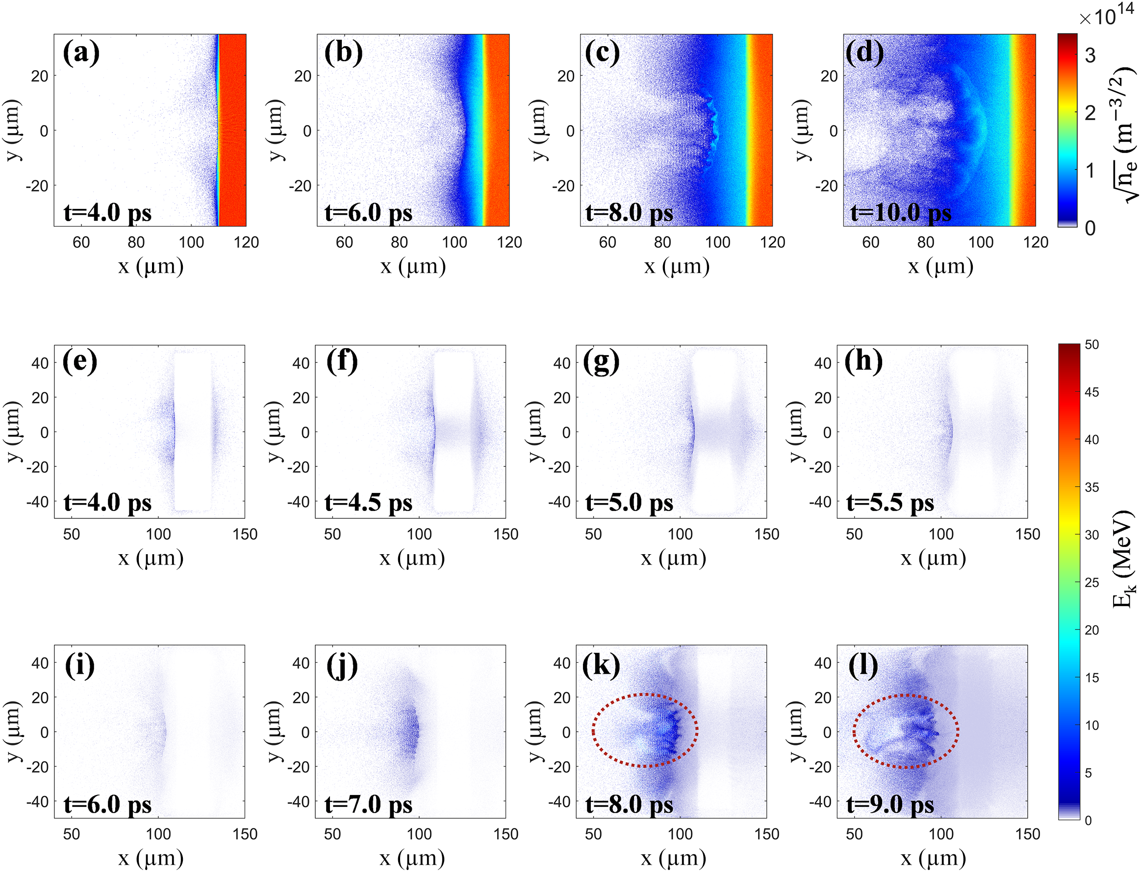
The simulation results suggest that, under dual-pulse driving, the delayed second pulse interacts with the low-density plasma expanding in front of the target and thereby further enhances electron acceleration ahead of the foil. Figures 4(a)–4(d) show the electron number-density distributions at selected times. In the single-pulse case, the laser pulse has already been reflected from the planar target and has left the simulation window by
$t=6\;\mathrm{ps}$
 , leaving only an expanding plasma plume. In the dual-pulse case, the first pulse has likewise left the simulation window by this time and has produced a front-side plasma expansion. A relatively dense plasma layer expands over a region of approximately 10 μm upstream of the front surface of the solid target, causing the critical-density surface to shift toward the laser-incident side. The delayed second pulse then interacts with this pre-expanded plasma. During its propagation toward the target, the second pulse further reshapes the preplasma density profile. The target-front plasma continues to expand toward the laser-incident side while being compressed toward the target by the incident laser pulse. As a result, an overdense plasma layer with a thickness of approximately 1–3 μm is compressed and formed about 10 μm in front of the target, and the effective reflection surface of the laser field moves to this position. The laser field is subsequently reflected from this target-front overdense layer, and the reflected laser couples to the underdense plasma extending several tens of micrometers in front of the target.
Target-front simulation results. Panels (a)–(d) show the electron number–density distributions at selected times, with the color scale plotted as
$\sqrt{n_\mathrm{e}}\;\left(\mathrm{in}\ {\mathrm{m}}^{-3/2}\right)$
 , rather than
${n}_\mathrm{e}$
 itself, to improve the visibility of low-density front-side plasma structures. In the single-pulse case, the laser pulse has propagated out of the simulation window by
$t=6\;\mathrm{ps}$
 . Since the two pulses in the dual-pulse case are separated by a 4 ps delay, the laser–solid interaction and laser propagation before
$t=6\;\mathrm{ps}$
 are essentially the same in the single-pulse and dual-pulse cases. During this stage, plasma expansion occurs in front of the target, and a relatively dense plasma region extends over approximately 10 μm upstream of the front surface of the solid target, around
$x=100\;\unicode{x3bc} \mathrm{m}$
 in panel (b), causing the critical-density surface to shift toward the laser-incident side. Subsequently, the second pulse is incident on the target-front plasma. While the plasma continues to expand toward smaller x, it is compressed toward the target by the second laser pulse. As a result, an overdense plasma layer with a thickness of approximately 1–3 μm is formed about 10 μm in front of the target, around
$x=100\;\unicode{x3bc} \mathrm{m}$
 in panel (c), where the laser is reflected. Panels (e)–(l) show the corresponding distributions of the cell-averaged electron kinetic energy at selected times. After reflection, the laser pulse interacts with the target-front plasma, undergoes filamentation and drives multiple plasma channels, leading to enhanced laser-energy absorption and backward electron acceleration toward the laser-incident side.

Figure 4 Long description
A multi-panel simulation result.
Top row, panels a through d, show electron number density distributions. The x-axis ranges from 50 to 120 micrometers and the y-axis from minus 30 to 30 micrometers. The color scale represents the square root of n sub e in units of m super minus 3 over 2, ranging from 0 to 3 times 10 super 14.
* Panel a at t = 4.0 p s shows a sharp vertical boundary at x = 110 micrometers.
* Panel b at t = 6.0 p s shows plasma expansion toward the left, reaching x = 100 micrometers.
* Panel c at t = 8.0 p s shows a compressed overdense layer forming around x = 100 micrometers with visible rippling.
* Panel d at t = 10.0 p s shows further expansion and complex filamentary structures extending toward x = 60 micrometers.
Middle and bottom rows, panels e through l, show cell-averaged electron kinetic energy E sub k in M e V. The x-axis ranges from 40 to 150 micrometers and the y-axis from minus 45 to 45 micrometers. The color scale ranges from 0 to 50 M e V.
* Panels e through h (t = 4.0 to 5.5 p s) show initial energy deposition at the target front surface near x = 110 micrometers.
* Panels i and j (t = 6.0 and 7.0 p s) show the energy distribution shifting as the second pulse interacts.
* Panels k and l (t = 8.0 and 9.0 p s) feature a red dashed oval highlighting a region of enhanced energy between x = 50 and 110 micrometers, where multiple plasma channels and backward electron acceleration are visible as dark blue filamentary structures.
The simulations further show that, owing to the irregular transverse shape of the target-front dense layer and the nonuniform density distribution of the preplasma, the reflected second laser pulse undergoes transverse filamentation. The laser pulse splits into several filamentary structures that interact with the plasma and drive multiple plasma channels in the target-front region. Figures 4(e)–4(l) show the spatial distributions of the cell-averaged electron kinetic energy at selected times. At
$t=9\;\mathrm{ps}$
 , the reflected second pulse enters the expanded front-side plasma region and drives the formation of several pronounced plasma channels. Many electrons undergo driven oscillations within these channels. When the electron oscillation frequency in a plasma channel approaches the Doppler-shifted laser frequency, resonant DLA can occur, allowing electrons to gain energy directly from the laser field[
Reference Pukhov, Sheng and Meyer-ter-Vehn
39
–
Reference Huang, Robinson, Zhou, Qiao, Liu, Ruan, He and Norreys
42
]. Previous studies have clarified the dynamics of DLA electrons and proposed unified scalings for electron motion and the associated betatron radiation. In this framework, the electron oscillatory motion can be characterized by the self-similar parameter
$S={n}_\mathrm{e}/\left({a}_0{n}_\mathrm{c}\right)$
 , which reflects the combined effects of the laser amplitude and plasma density on electron dynamics[
Reference Huang, Robinson, Zhou, Qiao, Liu, Ruan, He and Norreys
42
]. These features suggest that this resonance-based DLA process is likely to be an important contributor to the experimentally observed increases in electron energy and effective temperature, as well as to the enhanced electron yield under dual-pulse irradiation.
Simulated energy spectra of backward-propagating relativistic electrons crossing the target-front region at
$x=100\;\unicode{x3bc} \mathrm{m}$
 and
$x=75\;\unicode{x3bc} \mathrm{m}$
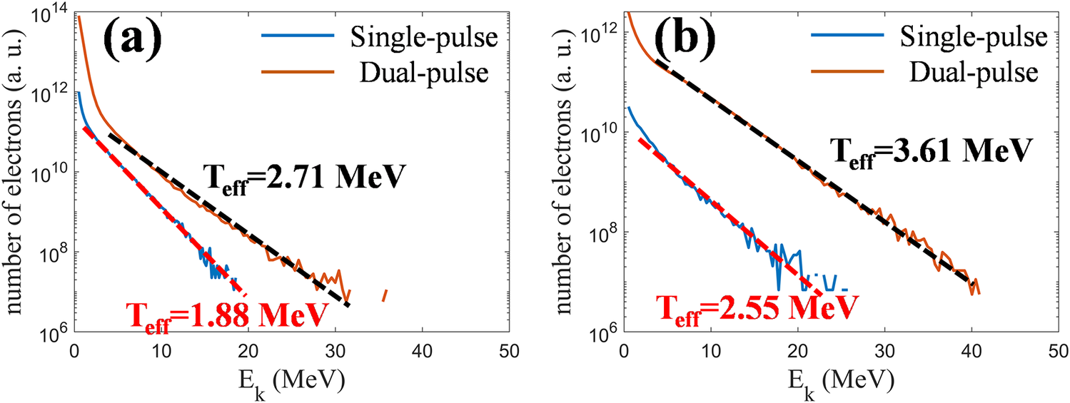
 are shown in Figures 5(a) and 5(b), respectively, for both single-pulse and dual-pulse driving conditions. Only electrons with kinetic energies above 0.5 MeV are included in the statistics. The results show that, under dual-pulse irradiation, the cutoff energy of electrons crossing the diagnostic plane located 35 μm in front of the target increases by approximately a factor of two. The simulated yield of electrons with energies above 0.5 MeV increases to about 70 times that in the single-pulse case, while the simulated yield of electrons above 5 MeV increases by nearly two orders of magnitude. In addition, the increase in the population of high-energy electrons is accompanied by an increase in the effective electron temperature. These simulation results are qualitatively consistent with the experimentally observed spectral evolution and yield enhancement. Although the total laser energy is only doubled in the dual-pulse case, the simulated backward-accelerated electron beam exhibits clear enhancement, as reflected by the increases in electron cutoff energy and electron temperature, together with the substantial enhancement of electron yield.
Simulated energy spectra of backward-propagating electrons recorded at two virtual probe positions in front of the target. Panels (a) and (b) correspond to x = 100 μm and x = 75 μm, respectively, namely 10 and 35 μm in front of the target-front surface. The blue and orange curves denote the single-pulse and dual-pulse simulations, respectively. The electrons counted here have
${p}_x<0$
 and therefore propagate toward the laser-incident side after being accelerated in the target-front plasma. The dashed lines indicate exponential fits used to estimate the effective temperature of the high-energy electron tail. Compared with the single-pulse case, the dual-pulse case produces a higher cutoff energy, a larger electron yield and a more pronounced high-energy component, indicating enhanced electron acceleration associated with the interaction of the delayed pulse with the pre-expanded front-side plasma.

Figure 5 Long description
A multi-panel attribute space diagram consisting of two line graphs, labeled (a) and (b). Both panels share the same axes: the horizontal x-axis represents kinetic energy E sub k in M e V, ranging from 0 to 50; the vertical y-axis represents the number of electrons in arbitrary units on a logarithmic scale from 10 super 6 to 10 super 14.
Panel (a) shows data at x = 100 micrometers.
* A blue curve for single-pulse simulation starts at 10 super 12 and decays rapidly. A red dashed line fits its tail, labeled T sub eff = 1.88 M e V.
* An orange curve for dual-pulse simulation starts higher at 10 super 14 and decays more slowly. A black dashed line fits its tail, labeled T sub eff = 2.71 M e V.
Panel (b) shows data at x = 75 micrometers.
* The blue single-pulse curve starts near 10 super 11. Its exponential fit is labeled T sub eff = 2.55 M e V.
* The orange dual-pulse curve starts near 10 super 13 and extends further to the right than in panel (a), reaching approximately 40 M e V. Its exponential fit is labeled T sub eff = 3.61 M e V.
In both panels, the dual-pulse curves consistently maintain a higher electron count and a higher cutoff energy compared to the single-pulse curves.
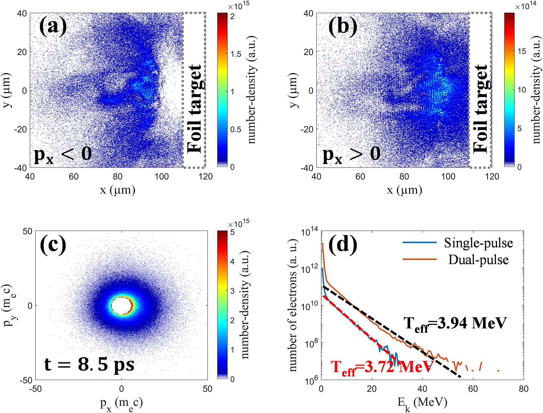
The simulation results further suggest that, under the dual-pulse scheme, electron acceleration is enhanced not only for backward-propagating electrons but also for forward-propagating electrons. Figures 6(a) and 6(b) show the spatial density distributions at
$t=8.5\;\mathrm{ps}$
 for backward-moving (
${p}_x<0$
 ) and forward-moving (
${p}_x>0$
 ) electrons with kinetic energy
${E}_{\mathrm{k}}>2.56\;\mathrm{MeV}$
 (corresponding to
$\gamma >6$
 ), respectively. The corresponding momentum phase-space distribution for electrons in the same energy range is shown in Figure 6(c). At
$t=8.5\;\mathrm{ps}$
 , the first laser pulse has completely left the simulation window. The leading part of the second pulse has already interacted with the solid target and been reflected, whereas its trailing part has not yet reached the target-front surface. As a result, part of the reflected laser light interacts with the low-density preplasma, accelerates electrons backward and further drives plasma expansion, while the remaining unreflected portion of the pulse continues to interact with the preplasma and accelerates electrons forward. As shown in Figures 6(a) and 6(b), within the plasma channel formed in front of the target, laser light propagating in both directions can drive resonant electron acceleration, with the acceleration direction aligned with the propagation direction of the corresponding pulse. This behavior supports the simulation-based interpretation that the dual-pulse scheme also promotes forward electron acceleration. All forward-propagating electrons were counted at
$x=140\;\unicode{x3bc} \mathrm{m}$
 , namely
$10\;\unicode{x3bc} \mathrm{m}$
 behind the rear surface of the target. A comparison of the electron energy spectra behind the target for the two driving schemes is shown in Figure 6(d). Under dual-pulse conditions, the cutoff energy of these electrons increases by approximately a factor of three, and the electron yield behind the target increases by a factor of several tens, accompanied by a rise in the effective temperature of the high-energy component (
${E}_{\mathrm{k}}>10\;\mathrm{MeV}$
 ).
Spatial, momentum-space and spectral distributions of energetic electrons under dual-pulse driving. Panels (a) and (b) show the spatial number-density distributions at t = 8.5 ps for energetic electrons with γ > 6 propagating backward (
${p}_x<0$
 ) and forward (
${{p}}_{{x}}>0$
 ), respectively. Panel (c) shows the corresponding
${p}_x$
 –
${p}_y$
 momentum phase-space distribution for electrons in the same energy range. Panels (a)–(c) indicate that, within the plasma channel formed in front of the target, the reflected and unreflected portions of the second pulse can drive backward and forward electron acceleration, respectively. Panel (d) shows the energy spectra of forward-propagating electrons recorded at
$x=140\;\unicode{x3bc} \mathrm{m}$
 , that is, 10 μm behind the rear surface of the target, for the single-pulse and dual-pulse cases. Compared with the single-pulse case, the dual-pulse case gives a higher cutoff energy, a higher effective temperature and a larger electron yield behind the target, indicating that dual-pulse driving enhances not only backward electron acceleration in front of the target but also the forward electron beam emerging from the rear side.

Figure 6 Long description
A four-panel scientific visualization.
Panel a and b: Spatial heatmaps with x and y axes in micrometers ranging from 40 to 120 and negative 40 to 40 respectively. A vertical dashed rectangle labeled Foil target is positioned at x equals 110 to 120.
* Panel a shows backward-propagating electrons (p sub x less than 0) with a number-density peak near 2 times 10 super 15 a. u. concentrated between x equals 80 and 100.
* Panel b shows forward-propagating electrons (p sub x greater than 0) with a lower density peak near 15 times 10 super 14 a. u. in a similar spatial region.
Panel c: A momentum phase-space distribution at t equals 8.5 p s. The x-axis is p sub x (m sub e c) and the y-axis is p sub y (m sub e c), both ranging from negative 50 to 50. The distribution is a central circular cloud with the highest density (5 times 10 super 15 a. u.) at the core, tapering outward.
Panel d: A semi-logarithmic line graph of the energy spectra. The x-axis is E sub k (M e V) from 0 to 80, and the y-axis is the number of electrons (a. u.) from 10 super 6 to 10 super 14.
* The Single-pulse case (blue line) shows a steep decline, with an effective temperature T sub e f f equals 3.72 M e V indicated by a red dashed fit line.
* The Dual-pulse case (orange line) maintains a higher electron yield across all energies, with a higher cutoff energy and an effective temperature T sub e f f equals 3.94 M e V indicated by a black dashed fit line.
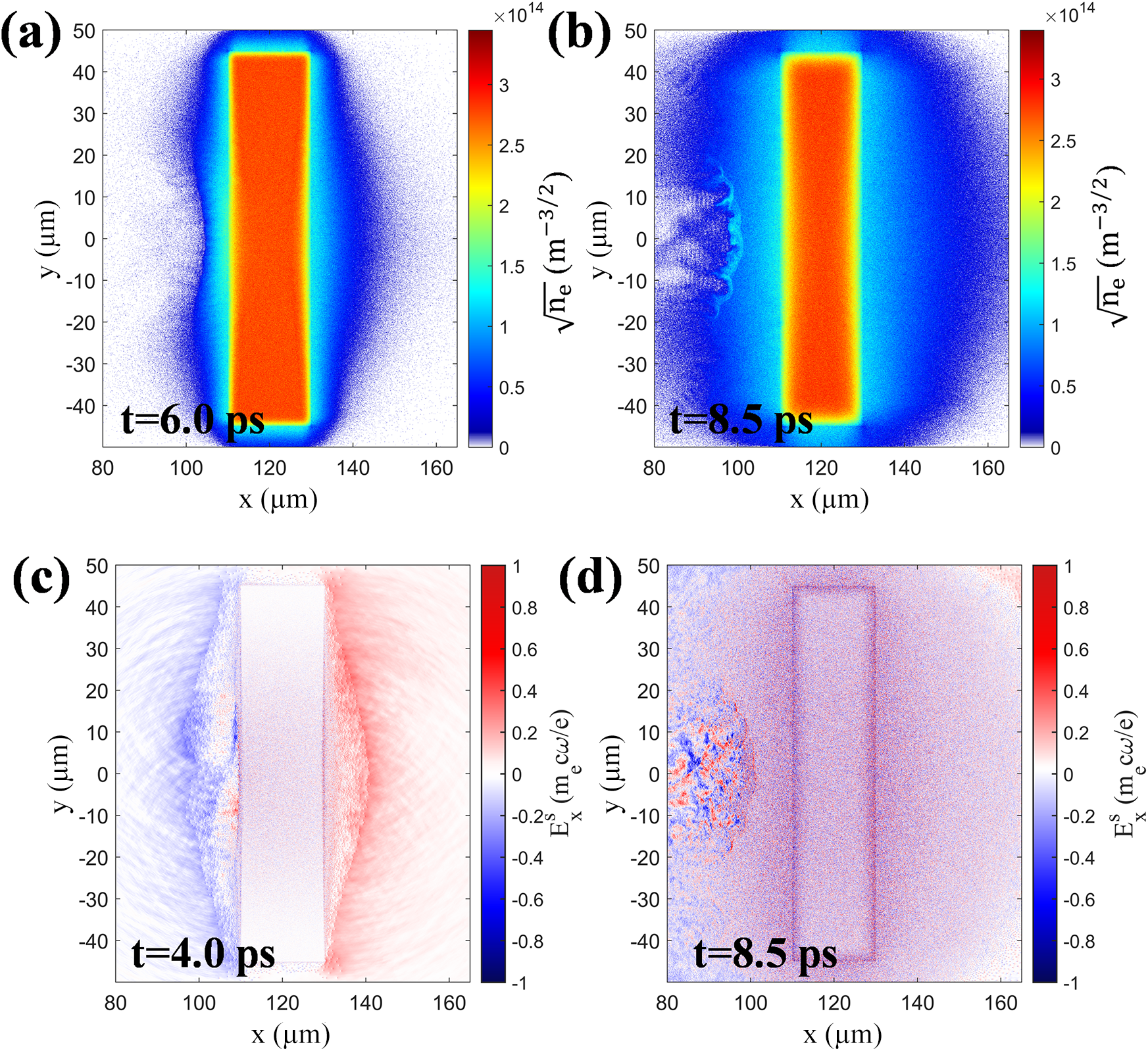
The different behavior of the proton cutoff energy can be understood from the rear-side plasma evolution. Figures 7(a) and 7(b) show the electron number-density distributions at two representative times, corresponding to the stage after the first pulse has interacted with the foil target and the stage when the delayed second pulse is interacting with the foil target, respectively. Figures 7(c) and 7(d) show the spatial distributions of the rear-side quasi-static electric field when the first and second pulses interact with the foil target, respectively. During the interaction of the first picosecond pulse with the foil, hot electrons expand from the rear side and establish a sheath field for proton acceleration. At the later stage of the first-pulse interaction and during the delay between the two pulses, the rear-side plasma continues to expand, which broadens the rear-side density scale length and reduces the local peak sheath field. When the delayed second pulse reaches the target after a 4-ps delay, the rear side has already undergone pronounced pre-expansion, and the rear-side hot-electron expansion continues to evolve during the second-pulse interaction. The simulation results show that a pronounced rear-side sheath field suitable for further proton acceleration is not re-established during the second-pulse stage. This behavior is consistent with the experimental observation that the proton cutoff energy does not show a clear enhancement under dual-pulse irradiation. Therefore, the dual-pulse scheme mainly enhances the coupling of the delayed pulse to the front-side low-density plasma and the associated high-energy electron generation, while the proton cutoff energy remains comparable to that in the single-pulse case.
Rear-side plasma evolution and sheath-field distributions obtained from the simulations. Panels (a) and (b) show the electron number-density distributions at t = 6.0 ps and t = 8.5 ps, respectively, with the color scale plotted as
$\sqrt{n_\mathrm{e}}$
 to improve the visibility of the expanded plasma structures. Panel (a) corresponds to the stage after the first pulse has interacted with the foil target, while panel (b) corresponds to the stage when the delayed second pulse is interacting with the target and the front-side plasma. Panels (c) and (d) show the corresponding rear-side quasi-static longitudinal electric field
${E}_x^\mathrm{s}$
 , normalized to
${m}_\mathrm{e}{\omega}_0c/e$
 , at t = 4.0 ps and t = 8.5 ps, respectively. At t = 4.0 ps, a clear rear-side sheath field is formed by the first-pulse interaction. By t = 8.5 ps, the rear-side plasma has undergone pronounced expansion, and no pronounced rear-side sheath field suitable for further strong proton acceleration is re-established during the second-pulse stage. These results indicate that rear-side plasma expansion limits the further enhancement of the proton cutoff energy from target-normal sheath acceleration (TNSA) under the present dual-pulse conditions.

Figure 7 Long description
A multi-panel simulation set with four panels labeled a through d. All panels share an x-axis from 80 to 160 micrometers and a y-axis from -40 to 50 micrometers.
* Panel a: Electron density at t = 6.0 p s. A central rectangular foil target is located between x = 110 and 130. The density is highest in the center (red) and expands outward (blue).
* Panel b: Electron density at t = 8.5 p s. The plasma has expanded significantly further from the target compared to panel a, particularly on the left side where turbulent structures are visible.
* Panel c: Longitudinal electric field E super s sub x at t = 4.0 p s. A strong sheath field is visible as a distinct red region on the right side of the target (x = 130 to 140) and a blue region on the left.
* Panel d: Longitudinal electric field at t = 8.5 p s. The field is largely dissipated, showing a noisy, low-intensity distribution across the entire area with no clear sheath structure remaining at the target boundaries.
Color scales for density (panels a and b) range from 0 to 3.5 times 10 super 14 m super -3/2. Color scales for the electric field (panels c and d) range from -1 to 1 normalized units (m sub e c omega sub 0 / e).
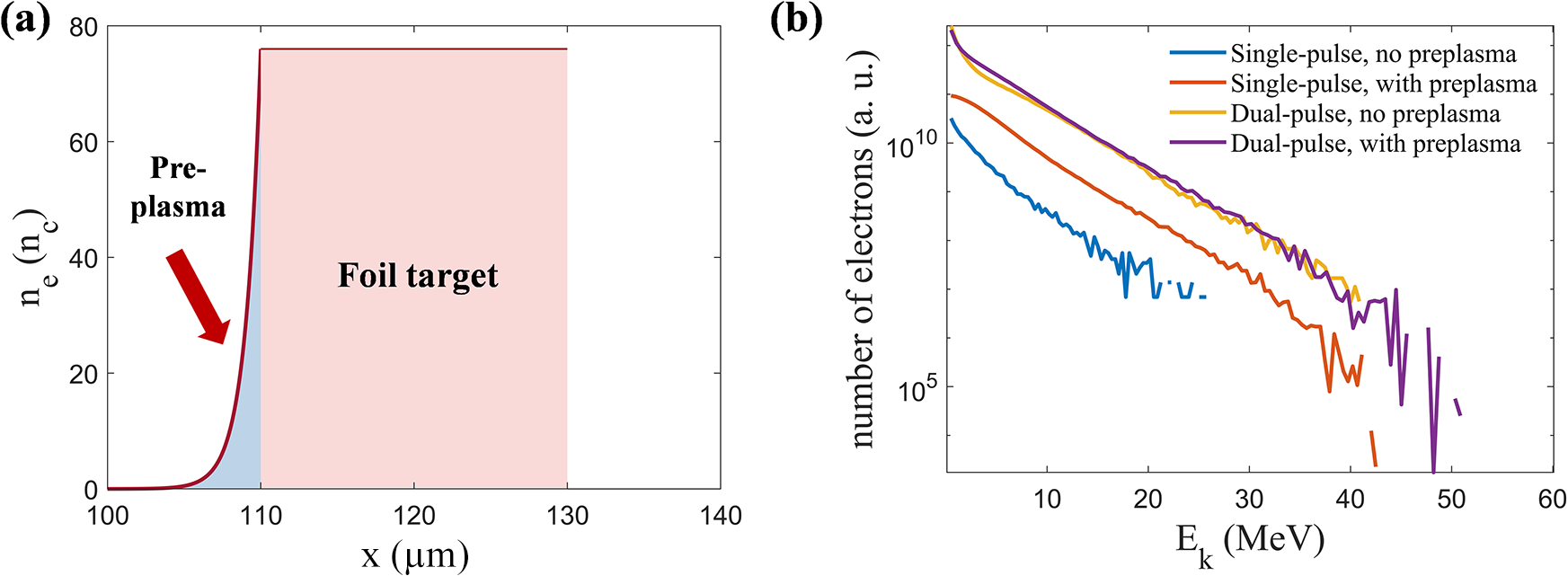
In realistic experiments, a low-intensity prepulse may interact with the front surface of a solid target before the arrival of the main picosecond pulse, thereby producing a finite-scale front-side preplasma. To examine whether such an initial preplasma modifies the main conclusion of enhanced electron acceleration under dual-pulse irradiation, we performed additional comparison simulations including an initial front-side preplasma. As shown in Figure 8(a), an exponential low-density plasma ramp was imposed in the region 100 μm < x < 110 μm in front of the foil target, with an electron-density profile given by
${n}_\mathrm{e}=76{n}_\mathrm{c}\exp \left[\left(x-110\;\unicode{x3bc} \mathrm{m}\right)/l\right]$
 , where
$l=1\;\unicode{x3bc} \mathrm{m}$
 . Figure 8(b) shows the front-side electron energy spectra obtained under single-pulse and dual-pulse irradiation with different initial front-side plasma conditions. The spectra were obtained for electrons with kinetic energies above 0.5 MeV crossing a diagnostic plane 35 μm in front of the target and propagating toward the laser-incident side. In the single-pulse case, the presence of the initial preplasma increases both the electron cutoff energy and the electron yield, indicating that a low-density plasma in front of the target can enhance laser-energy coupling and electron acceleration. Nevertheless, even with the initial preplasma, the electron yield in the single-pulse case remains much lower than that in the dual-pulse case, by approximately one order of magnitude. In the dual-pulse case, the electron spectrum obtained with the initial preplasma is very close to that obtained without the initial preplasma, indicating that the main physical picture of enhanced electron acceleration under dual-pulse irradiation does not rely on an ideal sharp front-surface boundary. These results show that the front-side low-density plasma indeed facilitates laser–plasma coupling, while the conclusion that the first pulse self-consistently reshapes the front-side plasma and enhances the coupling of the delayed pulse remains robust against the presence of an initial preplasma under the present parameters.
Effect of an initial front-side preplasma on electron acceleration. (a) Initial electron-density profile used in the simulations with a prescribed front-side preplasma. The foil target is located at 110 μm < x < 130 μm, and an exponential low-density plasma ramp is imposed within approximately 10 μm in front of the target, with
${n}_\mathrm{e}=76{n}_\mathrm{c}\exp \left[\left(x-110\;\unicode{x3bc} \mathrm{m}\right)/l\right]$
 , where
$l=1\;\unicode{x3bc} \mathrm{m}$
 . (b) Simulated energy spectra of backward-propagating electrons recorded 35 μm in front of the target for single-pulse and dual-pulse irradiation, with and without the initial preplasma. Only electrons with kinetic energies above 0.5 MeV are included in the statistics. The initial preplasma increases the electron cutoff energy and yield in the single-pulse case, indicating enhanced laser coupling to the front-side low-density plasma. However, the single-pulse electron yield remains much lower than that in the dual-pulse cases, and the dual-pulse spectra with and without the initial preplasma are similar. These results indicate that the conclusion of enhanced electron acceleration under dual-pulse irradiation remains robust against the presence of an initial front-side preplasma under the present simulation conditions.

Figure 8 Long description
Panel a is a line graph of electron density n sub e in units of n sub c versus position x in micrometers. The x-axis ranges from 100 to 140. A red line shows a low-density exponential ramp labeled Pre-plasma starting at x equals 100 and rising to meet a solid rectangular block labeled Foil target. The foil target is shaded light red and spans from x equals 110 to 130 with a constant density of approximately 76. A red arrow points down and to the right toward the pre-plasma ramp.
Panel b is a semi-logarithmic line graph showing the number of electrons in arbitrary units on the y-axis versus kinetic energy E sub k in M e V on the x-axis. The y-axis uses a log scale from 10 super 5 to 10 super 10. Four curves are shown.
1. Single-pulse, no preplasma (blue line): The lowest curve, starting at 10 super 10 and dropping sharply to a cutoff near 25 M e V.
2. Single-pulse, with preplasma (orange line): Positioned above the blue line, showing higher yield and a cutoff near 42 M e V.
3. Dual-pulse, no preplasma (yellow line): Significantly higher yield than single-pulse cases, following a linear decay on the log scale with a cutoff near 50 M e V.
4. Dual-pulse, with preplasma (purple line): Overlaps almost exactly with the yellow dual-pulse curve, ending at a similar cutoff near 50 M e V.
In summary, the simulations suggest that the backward- and forward-propagating energetic-electron populations are both enhanced under dual-pulse driving. This result provides a qualitative physical framework for interpreting the experimentally observed increases in peak EMP amplitude and neutron yield. Previous studies have shown that, in high-power laser–target experiments, the EMP strength is positively correlated with the hot-electron charge[ Reference Xie, Wang, Li, Deng, Teng, Zhang, Tian, Wu, Gu, Zhou and Li 14 , Reference He, Wang, Deng, Feng, Xia, Hu, Zhu, Xie, Yuan, Zhang, Lu, Yang, Cheng, Li, Yan, Fang, Li, Zhou, Li, Chen, Lin and Yan 15 ]. Although no clear enhancement of proton cutoff energy is observed under the present dual-pulse conditions, the substantially increased high-energy electron population may enhance bremsstrahlung photon production in the converter target, which could in turn increase the probability of photonuclear neutron generation. The experimental observations are broadly consistent with this picture: in addition to the pronounced enhancement of front-side electron acceleration, dual-pulse irradiation is accompanied by an approximately 10–30-fold increase in the peak EMP amplitude and by an increase in neutron yield by factors of tens, up to nearly two orders of magnitude.
5 Conclusion
Leveraging the dual-beam petawatt-class picosecond capability of the SG-II Upgrade facility, we carried out combined experiments and 2D PIC simulations of dual picosecond laser pulses interacting with planar metal foil targets. Experimentally, the clearest evidence for enhanced laser–target coupling under dual-pulse irradiation is provided by the electron measurements, which show increases in the electron cutoff energy, effective electron temperature and fast-electron charge. In addition, increases in peak EMP amplitude and neutron yield are also observed. Taken together, these observations are consistent with the interpretation that dual-picosecond-pulse driving strengthens fast-electron generation and is accompanied by the enhancement of multiple secondary-source signatures.
Two-dimensional PIC simulations further support a qualitative picture of enhanced laser-energy coupling under dual-pulse driving. After the arrival of the first picosecond pulse, an extended low-density plasma region is formed in front of the target. The delayed second pulse then couples efficiently to this underdense preplasma and drives the formation of a pronounced channel-like structure during its propagation and subsequent reflection, through which electron acceleration is further strengthened via DLA. This process increases both the energy and the yield of backward-propagating electrons on the front side of the target and enhances the forward electron beam at the target rear, thereby providing a plausible basis for interpreting the correlated enhancement of multiple secondary-source signatures, particularly peak EMP amplitude and neutron yield. Owing to the 2D geometry and the simplified target model, the simulations are intended to provide a qualitative interpretation rather than a strict quantitative reproduction of the experiment. Nevertheless, they are qualitatively consistent with the experimentally observed spectral evolution and yield enhancement, suggesting that the underdense preplasma established through dual-pulse delay control is likely to play an important role in the enhanced coupling and the enhancement of multiple secondary-source signatures.
Overall, the present work suggests that the value of dual-pulse petawatt-class picosecond laser driving lies not simply in increasing the total incident energy but also in introducing a temporal degree of freedom for shaping the plasma environment encountered by the delayed pulse. Enabled by the newly established dual-beam capability of the SG-II Upgrade facility, this approach makes it possible to study dual-pulse interactions with planar foil targets under realistic large-facility conditions. More broadly, it suggests the possibility of correlated enhancement of multiple secondary-source signals through temporal control of the coupling environment. Compared with conventional single-beam multi-picosecond laser–solid interactions, the present scheme highlights the potential of dual-pulse control to link enhanced electron generation with correlated improvements in EMP emission and neutron production. Further work will focus on systematic optimization of the pulse delay, energy partition, target material and target thickness under dual-pulse driving conditions.
Acknowledgements
This work was supported by the National Natural Science Foundation of China (Grant Nos. U2241281 and 12120101005), the Science Challenge Project (Grant No. TZ2025014) and the National Key R&D Program of China (Grant No. 2024YFA1613400). Z. Wang gratefully acknowledges valuable discussions with Y. X. Song from the Shanghai Institute of Laser Plasma and Z. L. Han from the Laser Fusion Research Center.










 Open access

