Introduction
Apatite-phase oxides based on rare-earth silicates [A 10 −x (SiO4)6O2±x , A = rare-earth cation][ Reference Nakayama, Sakamoto, Higuchi, Kodaira, Sato, Kakita, Suzuki and Itoh 1 – Reference Kuang, Green, Niu, Zajdel, Dickinson, Claridge, Jantsky and Rosseinsky 6 ] are gaining much attention for potential use in solid oxide fuel cell (SOFC) devices for the high ionic or mixed conductivity at lower temperatures (<~1000 K) compared with conventional ionic conductors such as yttria-stabilized zirconia.[ Reference Kuang, Green, Niu, Zajdel, Dickinson, Claridge, Jantsky and Rosseinsky 6 ] In addition, a wide choice for cation substitution and compositional variation, and also the ability to tune ionic conductivity by altering the stoichiometry of the cation sub-lattice make this class of materials particularly promising for high-performance thin-film SOFC application.
Despite the fact that oxy-apatites show superior conductivity at moderate temperatures (<1000 K), traditional bulk apatite synthesis still requires high temperatures (>~1800 K),[ Reference Beaudet-Savignat, Vincent, Lambert and Gervais 3 , Reference Leon-Reina, Losilla, Martinez-Lara, Bruque and Aranda 7 – Reference Risbud, Helean, Wilding, Lu and Navrotsky 12 ] which limits the implementation of these materials for practical device applications. Instead, thin-film systems are likely synthesized at much lower temperatures in part due to smaller length-scales, which require less diffusion kinetic energy during solid-state reactions than that for larger volume bulk phase synthesis. Therefore, the objective of this study is to synthesize and characterize thin-film oxy-apatites at lower temperatures than those used in bulk synthesis and also to integrate thin-film apatites in SOFC devices. To increase the electronic portion of the total conductivity, ZnO is incorporated as dopant in a cerium silicate system. This work follows a previous study[ Reference Lee, Guan and Ramanathan 13 ] in which the feasibility of cerium silicate-based apatites in the use in SOFCs is described with systematical characterizations of the electrical, chemical, and elemental distribution properties. In this paper, we report on: (1) the effect of electrode contact resistance on the performance of apatite anode SOFC devices, as well as (2) the synthesis of ZnO-doped Ce4.67(SiO4)3O (ZCS) thin-film apatites at 973 K through thin-film interfacial reactions, and (3) their high conductivity >~0.05 S/cm.
Growth of oxy-apatite thin films
Oxy-apatites based on ZCS were synthesized using room-temperature radio frequency (rf) magnetron sputtering followed by low oxygen partial pressure [p(O2) < ~10−17 atm] annealing at 973 K. To incorporate ZnO in the cerium silicate matrix, multi-layer structures of CeO2–SiO2/ZnO/CeO2–SiO2 were grown on 0.5 mm-thick single-crystalline Al2O3 (0001) substrates (MTI Corp.): first, CeO2–SiO2 was co-sputtered from commercially available CeO2 and SiO2 ceramic targets (purity 99.99%, AJA International Inc.). ZnO thin film was then deposited from a single ZnO target (99.99%, AJA International Inc.) on top of CeO2–SiO2 film and last, another CeO2–SiO2 was grown on ZnO/CeO2–SiO2. All sputter depositions were performed using 2 in targets at an rf power of 100 W, a working pressure of 4 mTorr with an O2/Ar sputter gas ratio of 2/38 in sccm. Before all depositions, the sputter chamber was pump down to a base pressure below approximately 5 × 10⁻⁷ Torr and targets were pre-sputtered for 1000 s to remove any surface contamination and also to achieve uniform distribution of sputter-gas flow inside the chamber. During depositions, the substrate holder on which substrates were loaded was rotated at a rate of 15 rpm to ensure the surface homogeneity of the films.
The resulting tri-layer films of CeO2–SiO2/ZnO/CeO2–SiO2 were annealed in a custom-built environmental furnace that systematically controls oxygen partial pressure ranging from atmospheric pressure to ~10−25 atm during annealing. Oxygen partial pressure was altered using the gas mixture of air, Ar, H2, and H2O and monitored by an in situ oxygen gas sensor.
Characterizations of the oxy-apatite thin films
Pre-annealing at 973 K was made on as-grown CeO2–SiO2/ZnO/CeO2–SiO2 samples for more than 2 days to incorporate ZnO well into the CeO2–SiO2 system by the interfacial reaction. Then, the samples were kept at 973 K and the total conductivity of the films was characterized in situ during annealing process as a function of oxygen partial pressure. Typical current–voltage characteristics were measured using a Keithley 236 source measurement unit to evaluate resistance of the samples and hence to determine the conductivity of samples during annealing.
Amorphous/crystalline structure and preferred orientation of as-processed and annealed samples were characterized using a Bruker D2 Phaser x-ray diffractometer using Cu K α radiation (λ = 0.154 nm) at 30 kV and 10 mA at diffraction angles, 2θ ranging from 10° to 100°.
Proto-type SOFC application
Apatites synthesized in this study were integrated into SOFCs as anodes. Commercially available Sc-stabilized ZrO2 (ScSZ, 150 µm-thick)/lanthanum strontium cobalt ferrite (LSCF, 30 µm-thick) substrates (Fuel Cell Materials) were used as electrolyte/cathode for SOFC application to evaluate the performance of thin-film apatite anodes. A custom-built fuel cell test system with a gold ring seal was used to characterize the apatite anode SOFCs. Anode current collection was performed with a gold gasket and a stainless steel base, and cathode current was collected through a stainless steel cap painted with silver paste and a Pt-plated tungsten tip. For the SOFC characterizations, 3% humidified H2 was flowed to the anode side at a flow rate of 80 cm3/min, while laboratory air was used as the oxidant at the cathode side. Current density–voltage characteristics were evaluated from open-circuit voltage to 0 V at a rate of 20 mV/s. The electrochemical active area for fuel cell performance was defined as the area within the gold gasket (0.45 cm2). The test station was ramped at 20 K/min from room temperature to the desired temperatures. All electrochemical measurements were performed with a Solartron SI 1287 electrochemical interface coupled with an SI 1260 impedance/gain-phase analyzer. The frequency range from 106 to 0.1 Hz was employed for impedance measurements. More detailed information of the test cell structure and the station can be found elsewhere.[ Reference Jiang, Guan, Lattimer, Friend, Verma, Tsuchiya and Ramanathan 14 ]
Identification of the formation of oxy-apatite phase
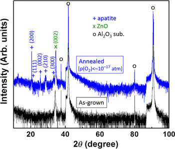
X-ray diffraction (XRD) analysis was made on the samples to investigate the crystallographic structures and also to effectively identify phase transformations of the samples after annealing. Figure 1 shows XRD patterns that were obtained from the samples in the as-processed condition (lower curve) and after annealing (upper curve) at 973 K and very low p(O2) below 10−17 atm. The as-deposited sample shows a crystalline peak associated with wurtzite ZnO (002) at the diffraction angle, 2θ ~ 34.1°, which is the characteristic peak of the c-axis-oriented ZnO.[ Reference Oka, Kimura, Yagi, Taketoshi, Baba and Shigesato 15 – Reference Hong, Paik, Hwang, Lee, deMello and No 17 ] No crystallographic peaks were seen for as-processed CeO2–SiO2 films and, therefore, it is concluded that the room temperature co-sputtered CeO2–SiO2 yields thin films in amorphous state. Strong Al2O3 substrate peaks are detected at 2θ ~ 37.55°, 41.66°, 80.08°, and 90.72° in the as-deposited sample. After annealing these samples at 973 K and p(O2) <~10−17 atm for 2 days, significant crystallographic features are observed in the diffraction pattern and these peaks are found to be apatite phase according to JCPDS No. 43–0441. Poly-crystalline apatite phases of ZCS (200), (111), (002), (210), and (300) are shown at 2θ of 20.49°, 21.12°, 25.47°, 28.57°, and 33.35°, respectively. The XRD analysis clearly reveals that the low p(O2) annealing and the interfacial reaction at a modest temperature of 973 K promisingly synthesizes thin-film oxy-apatites in the present study.
XRD patterns of the room-temperature-processed CeO2–SiO2/ZnO/CeO2–SiO2 (tri-layer films, lower curve) in the as-grown state and the annealed sample of apatite of ZnO-doped ZCS (upper curve).

In situ and ex situ conductivity measurements
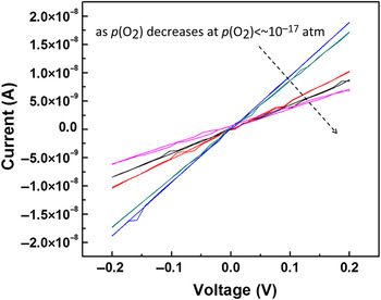
During annealing at 973 K, total conductivity of the pre-annealed samples was investigated in situ as a function of oxygen partial pressure. At each p(O2), we assumed that the equilibrium state has been reached when the results of repeated I–V measurements are reasonably constant. In situ conductivity was determined by monitoring the current across the sample as a function of applied voltage and by using typical Ohm's law and the geometric configuration of the sample. Figure 2 presents the double-sweep (forward and reverse) I–V plots measured at various p(O2) below 10−17 atm. No significant hysteresis behavior between the forward and reverse plots is observed, which indicates that the synthesized ZCS apatites are homogeneous with no considerable traps or defects in the films.[ Reference Streetman and Banerjee 18 ]
The current–voltage characteristics of the ZnO-doped ZCS apatite obtained in situ at p(O2) below 10−17 atm during annealing at 973 K.

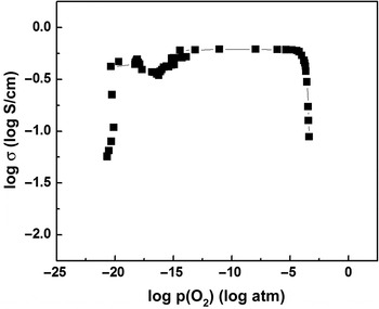
The in situ conductivity measurements were repeated at various p(O2) and the plot of log(σ) versus log[p(O2)] is shown in Fig. 3. The oxygen partial pressure was reduced by increasing the fraction of H2 in the H2–Ar–air–H2O gas mixture. The plot in Fig. 3 shows three different regimes of the conductivity as a function of p(O2): first, the conductivity initially increased from ~0.05to 0.56 S/cm at higher p(O2) regime until ~10−5 atm and then the conductivity (~0.56 S/cm) remained unchanged at p(O2) ranging from 10−5 to 10−15 atm. Last, a further decrease in p(O2) below 10−17 atm leaded to a decrease in conductivity.
Plot of log(σ)–log[p(O2)] where the conductivity was evaluated in situ as a function of oxygen partial pressure during annealing at 973 K.

The initial σ increase is likely attributed to a formation of oxygen vacancy defects (VO ••) due to the addition of ZnO to the cerium–silicate system because ZnO is well known to be doped by the generation of VO •• under reducing atmosphere.[ Reference Chiang, Birnie and Kingery 19 ] The defect reaction for doping ZnO in CeO2 or SiO2 can be written as: ZnO → Zn′′ Ce/Si + V O •• + O O x , where Zn′′ Ce/Si , V O •• and O O x denote Zn on the site of Ce or Si with a charge of negative two (i.e., −2), a doubly-charged oxygen vacancy, and a neutral oxygen on the oxygen site, respectively. This is also supported by the fact that the initial increase in conductivity was not observed in undoped cerium–silicate.[ Reference Karthikeyan, Tsuchiya and Ramanathan 2 ] In addition, the defect formation due to the interaction of the oxides with the gas phase can be described by the following equilibrium reaction,[ Reference Lee, Guan and Ramanathan 13 , Reference Chiang, Birnie and Kingery 19 , Reference Lee and Paine 20 ] O O x = 1/2O 2(g) + V O •• + 2e′. Since in this equation a doubly-charged oxygen vacancy contributes two free electrons, the formation of oxygen vacancies in ZnO increases the electronic portion of the conductivity, which is predominant at p(O2) > ~10−5 atm, and thereby the electronic portion of the conductivity increases as the oxygen partial pressure decreases.
The conductivity in Fig. 3 is shown to be nearly constant at p(O2) regime from 10−5 to 10−15 atm with decreasing p(O2). As p(O2) is further decreased from 10−15 to 10−17 atm, the conductivity slightly decreased and then increased, which is likely associated with the two different conduction mechanisms of vacancy-conduction [σ increases with decreasing p(O2)] and interstitial conduction [σ decreases with decreasing p(O2)]. At p(O2) regime below ~10−17 atm, the conductivity monotonically decreases with reducing oxygen partial pressure. In a conventional σ-p(O2) defect diagram (i.e., Brouwer diagram[ Reference Chiang, Birnie and Kingery 19 ]) in oxides, materials whose conduction mechanism is governed by vacancies show an increase in conductivity with decreasing p(O2), while materials dominated by oxide ion interstitial conduction present a decrease in conductivity, which is in the mixed conduction regime. Therefore, in this regime of p(O2) < ~10−17 atm, the resulting decrease in conductivity with decreasing p(O2) indicates the formation of cerium silicate-based apatite of which the conduction mechanism is dependent on the oxide ion interstitials.
The total conductivity of approximately 0.05–0.56 S/cm obtained from the ZnO-doped cerium-silicate apatites in the present study is considerably improved compared with previously reported apatites showing total conductivity of ~10−5–10−3 S/cm at 973 K.[ Reference Porras-Vazquez, Losilla, Leon-Reina, Marrero-Lopez and Aranda 9 , Reference Panteix, Julien, Bernache-Assollant and Abelard 21 – Reference Nakayama, Kageyama, Aono and Sadaoka 24 ] The modest temperature synthesis of cerium-silicate-based apatite and the superior total conductivity at low oxygen partial pressure is particularly promising for SOFC anode application that requires the use of materials with high mixed electronic/ionic conductivity and excellent stability in reducing anode atmosphere [i.e., low p(O2)]. The proto-type SOFC devices utilizing our apatite anodes were fabricated on the ScSZ/LSCF electrolyte/cathode configuration to evaluate the performance of cerium silicate-based apatite anode in SOFC and the results are discussed later in this report.
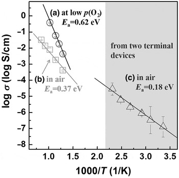
In situ conductivity measurements were repeated at several temperatures (>773 K) in air and low p(O2) conditions to compare the activation energy for the change in conductivity. In addition, the low-temperature conductivity was also measured ex situ from low dimension two-terminal devices that enable the measurement of much smaller conductivity at lower temperatures (<~320 K). Figure 4 shows the plots of log(σ) versus inverse absolute temperature (1/T), which clearly present that the conductivity of the samples are thermally activated. Note that the E a [0.62 eV in Fig. 4(a)] for the low p(O2) regime (i.e., for apatite phase) is higher than E a = 0.37 eV measured in air [Fig. 4(b)] at temperatures greater than 773 K. The higher E a of apatite is associated with the formation of oxide ion interstitials [Fig. 4(a)] that generally requires more energy than that of the creation of oxygen vacancies [Fig. 4(b)] in oxides.[ Reference Chiang, Birnie and Kingery 19 ] The low-temperature conductivity of apatite phase was activated with an E a of 0.18 eV. Since the conduction related to oxide ion interstitial was not observed at temperatures below 700 K in this study, the change in conductivity shown in Fig. 4(c) is possibly due to an increase in electronic portion of the conductivity.
Arrhenius plots of log(σ) versus inverse absolute temperature (T) from which the conductivity was thermally activated with an activation energy of: (a) 0.62 eV at high T and low p(O2)~ < 10−17 atm, (b) 0.37 eV at high T in air, and (c) 0.18 eV at low T in air.

SOFCs utilizing apatite anode
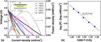
Thin-film ZnO-doped cerium silicate apatites were integrated as anodes in SOFC devices where ScSZ was used as electrolyte (150 µm-thick) and LSCF (30 µm-thick) as cathode. Since the ScSZ/LSCF electrolyte/electrode (commercially available from Fuel Cell Materials) system is a standard system which allows us to focus on the performance of our thin-film apatite anodes in fuel cells. Our SOFC devices of LSCF/ScSZ/ apatite fuel cell is schematically shown in Fig. 5 as inset. More detailed information of the test cell structure can be found elsewhere.[ Reference Jiang, Guan, Lattimer, Friend, Verma, Tsuchiya and Ramanathan 14 ] The performance of the SOFCs was evaluated using a custom-designed fuel cell test station whose details are described elsewhere.[ Reference Takagi, Lai, Kerman and Ramanathan 25 , Reference Kerman, Lai and Ramanathan 26 ] The plots of the voltage and power density as a function of current density for the fuel cell operated at various temperatures ranging from 723 to 823 K are shown in Fig. 5(a). The results demonstrate the feasibility of cerium-silicate-based apatite as anode for SOFCs. The open-circuit voltage measured in these temperatures is ~0.75 V, lower than the theoretical value of ~1.15 V calculated by oxygen partial pressure difference between the fuel and the air.[ Reference Jiang, Guan, Lattimer, Friend, Verma, Tsuchiya and Ramanathan 14 , Reference O'Hayre, Cha, Prinz and Colella 27 ] The deviation from the theoretical value is mainly attributed to sluggish reaction kinetics at the apatite anode at this low operating temperature range.[ Reference Haile 28 ] During the current density–voltage scan, the voltage drops due to various polarization losses, including activation polarization, ohmic polarization, and concentration polarization. The activation polarization is associated with the chemical and electrochemical reactions at the electrodes. The ohmic polarization is associated with the ohmic resistance of the electrodes, the electrolyte, the external wires, and all contact interfaces. The ohmic polarization varies linearly to the increase in current density due to the constant nature of the ohmic resistance. The concentration polarization is associated with mass transport limitations at the electrodes, and only becomes prominent at high limiting current densities.[ Reference O'Hayre, Cha, Prinz and Colella 27 ] The current density–voltage curves in Fig. 5(a) show an almost linear dependence of the voltage from OCV to 0 V on the current density over the range from 0 to less than 0.4 mA/cm2). This linear behavior indicates an almost constant total resistance during each scan, and it is likely attributed to the constant ohmic resistance of the cell and the sluggish kinetics of the electrode reactions. The total resistance can be estimated from the slope of the current density–voltage curve.
(a) Typical plots of voltage (left) and power density (right) versus current density of the SOFC device of LSCF/ScSZ/apatite as a function of temperatures ranging from 723 to 823 K. Inset shows a schematic (not to scale) of the SOFC device structure of LSCF/ScSZ/ZCS apatite as cathode/electrolyte/anode. (b) Arrhenius plot that presents the activation energy for power density of 0.71 eV.

The peak power density increases with operation temperature with activation energy of 0.71 eV as shown in Fig. 5(b), and a peak power density of approximately 0.06 mW/cm2 was achieved at 823 K as shown in Fig. 5(a). As a figure of merit, the power density of SOFCs utilizing electrolyte thicker than ~100 µm and all-oxide electrodes will be compared. The performance of our SOFCs with apatite anode demonstrated is comparable with those implementing 120 µm-thick ScSZ electrolyte (with La0.7Sr0.3VO3/YSZ anode, La0.8Sr0.2MnO3/Ce0.9Gd0.1O3 cathode)[ Reference Cooper, Channa, De Silva and Bayless 29 ] showing similar peak power density of ~0.1 mW/cm2 at 823 K (extrapolation result based on the reported data at higher temperatures). While noting that a variety of factors are important in evaluating performance of fuel cells for real-world application, this simple comparison shows encouraging performance of apatite-anode fuel cells that can motivate further interest in this material system as interesting candidates for electrochemical energy conversion devices.
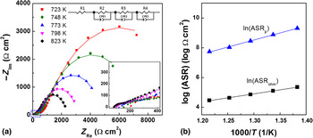
Although the SOFC results above present promising feasibility of the potential use of thin-film oxy-apatites for intermediate-temperature SOFCs, the performance shown in Fig. 5(a) is relatively low. To further investigate the fuel cells, in particular the factors contributing low device performance, impedance spectroscopy measurements were performed and the resulting spectra are shown in Fig. 6(a). An equivalent circuit [upper inset in Fig. 6(a)] consisting of a resistor and three series elements, each comprised a parallel resistor and a constant phase element, was used to fit the impedance data to quantify the ohmic resistance as well as the polarization resistance. The high-frequency intercept with the real axis corresponds to the cell area-specific ohmic resistance (ASRohm), which includes the ohmic resistance of the LSCF, the ScSZ electrolyte, the apatite, the external lead wires, and the contact resistances associated with all interfaces. In the lower inset in Fig. 6(a), magnifying the high-frequency regime, the values of ASRohm are found to be in between 90 and 200 Ω cm2 in the temperature range from 723 to 823 K. The activation energy for change in ASRohm is determined to be 0.46 eV from the Arrhenius plot in Fig. 6(b) (squares).
(a) Impedance measurements of the LSCF/ScSZ/ZCS apatite cell where the solid lines represent the fitting using an equivalent circuit (shown as upper inset) consisting of a resistor and three serial elements, each comprised a resistor and a constant phase element. Lower inset shows the magnified plot in the high-frequency regime (marked using a dotted blue rectangle). (b) Arrhenius plot of the ASRohm and ASRp as a function of inverse absolute temperature.

Since LSCF is a high-performance cathode material for SOFC with mixed ionic and electronic conductivities,[ Reference Sun, Hui and Roller 30 ] the polarization resistance of LSCF cathode under open-circuit condition was relatively small.[ Reference Yoshioka, Mitsui, Mineshige and Yazawa 31 ] Therefore, the majority of the polarization resistance of the cell is mainly due to the apatite anode. The area-specific polarization resistance (ASRp) of the anode can be extracted from the difference between the high-frequency intercept and the low-frequency intercept with the real axis. The Arrhenius plot for ASRp as a function of reciprocal temperature is shown in Fig. 6(b), and the activation energy was found to be 0.82 eV (triangles).
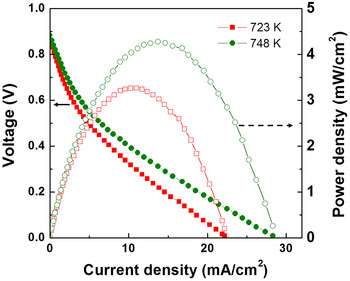
According to the impedance measurements discussed above, the performance of the SOFC devices implementing apatite anodes may be improved by reducing the cell ASRohm and the ASRp. Another set of SOFCs that include an additional Pt layer (100 nm thick) on top of ZCS apatite/ScSZ/LSCF were fabricated and the device performance was measured at intermediate temperatures of 723 and 748 K. The results are presented in Fig. 7. The open-circuit voltage increased from ~0.75 V (SOFC without Pt) to ~0.9 V. In particular, the current density and the peak power density are substantially enhanced by approximately two orders of magnitudes compared with those without Pt metallization layer. The current density–voltage curves shown in Fig. 7 exhibit typical activation polarization and ohmic polarization behavior. The initial sharp drop in voltage at the low-current density region indicates the dominating role of activation polarization. The linear slow drop in voltage at middle and high-current density regions indicates that the ohmic polarization became dominating. No concentration polarization behavior was observed at the high-current density region implying the absence of mass-transport limitation. This higher performance is attributed to not only reduced contact resistance by the addition of Pt between the apatite anode and the contact probe of the fuel cell measurement system, but also the catalytic activity of Pt for H2 oxidation reaction. The improved device performance shown in Fig. 7 clearly demonstrates the promising feasibility of the cerium-silicate-based apatites as anodes for intermediate-temperature thin-film SOFC application.
Typical plots of voltage (left) and power density (right) versus current density of the SOFC device with a contact metallization layer (Pt) on top of the apatites (i.e., LSCF/ScSZ/apatite/Pt) that show a significant improvement of the peak power density by two orders of magnitude at the same temperatures compared with SOFCs without a Pt layer.

Conclusion
Cerium-silicate-based oxy-apatites were synthesized through interfacial reactions and low oxygen partial pressure annealing at intermediate temperature of 973 K. The resulting apatite thin films present a considerably high total conductivity of ~0.05–0.56 S/cm in reducing conditions, which makes this class of materials promising for SOFC anode application. Proto-type apatite anode SOFCs were fabricated using a standard ScSZ/LSCF electrolyte/cathode structure. At intermediate temperatures <750 K, the maximum peak power density of approximately 5 mW/cm2 was achieved. The modest temperature synthesis of oxy-apatite thin films and the promising demonstration of SOFC anode application at temperatures below 750 K may be significant to the studies to develop materials that require high conductivity for high-performance SOFC application that can be processed and operated at intermediate temperatures.
Acknowledgment
This work was supported by the Baylor University faculty start-up funds.