1. Introduction
In robotic manipulation, compliance can be used to provide force regulation and to improve relative positioning [Reference Whitney1, Reference Mason and Brady2]. Compliance is the mapping between the force applied to a body and the displacement of the body. If the displacements from equilibrium are small, the relationship is linear, and the compliant behavior is most generally characterized by a stiffness matrix
 $\textbf {K}$
:
 \begin{equation} \textbf {w} = \textbf {K}\textbf {t}, \end{equation}
where
 $\textbf {K} \in {\mathbb R}^{6\times 6}$
is symmetric positive semidefinite (PSD),
 $\textbf {t} \in {\mathbb R}^6$
is the displacement twist of the body,
 $\textbf {w} \in {\mathbb R}^6$
is the wrench (force and moment) applied to the body. If the suspension is fully elastic, the behavior can be equivalently represented by the compliance matrix
 $\textbf {C}$
, the inverse of
 $\textbf {K}$
.
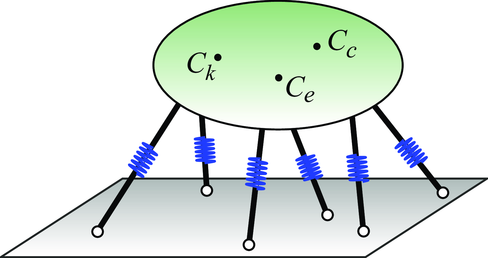
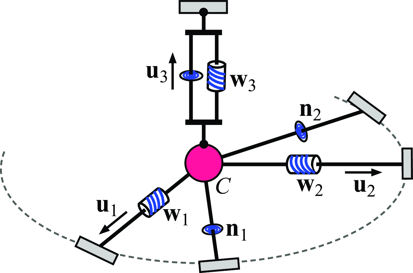
A general model of compliance is a rigid body suspended by an elastic mechanism as illustrated in Fig. 1. The two simplest types of elastic mechanisms are fully parallel and fully serial mechanisms. The analysis of a mathematical description of a general compliant behavior and an interpretation of the behavior in terms of the simplest mechanisms provides a foundation and guide for the design of compliant manipulators for dexterous robotic manipulation.
General model of compliance: rigid body suspended by elastic components. In general, the center of stiffness
 $C_k$
, the center of compliance
 $C_c$
and the center of elasticity
 $C_e$
are at different locations in space.

For any specified compliant behavior, there are some locations in physical space that are of particular interest. By placing a coordinate frame at one of these locations, the mathematical description of the stiffness or compliance matrix has a simpler form. These locations are defined as “centers” of the behavior and each characterizes the physical properties of the behavior in a different way. An understanding of these centers provides insight into general compliant behavior and guidance in compliant mechanism design. Specifically, this work is directed toward developing a better understanding of the concepts of center of stiffness [Reference Loncaric3], center of compliance [Reference Loncaric3], and center of elasticity [Reference Ciblak and Lipkin4]. In general, these three centers are located at different positions in space.
Here, compliant behaviors having coincident centers are analyzed. We investigate these concepts with the objective of evaluating behaviors in terms of elastic mechanism realizations that characterize the behavior in terms of directional decoupling and extremal properties.
1.1. Related work
Screw theory [Reference Ball5] has been widely used in the analysis of compliance [Reference Dimentberg6 –Reference Wang, Li, Yang, Hu and Zhao14]. Lie groups [Reference Loncaric3] and finite element method [Reference Pinto, Corral, Altuzarra and Hernández15] have also been used in the analysis of general spatial compliance.
Realization of an arbitrary compliance has been addressed in prior work. In refs. [Reference Huang and Schimmels16 –Reference Wen, Shin, Seo and Lee18], synthesis of planar compliance was developed for different types of mechanisms. In refs. [Reference Huang and Schimmels19,Reference Huang and Schimmels20], the space of and the realization of spatial compliant behaviors that can be achieved with a simple (line spring) parallel mechanism or a simple (revolute joint) serial mechanism were identified. Synthesis procedures for simple mechanism realization of compliant behavior were later improved for simple parallel mechanisms [Reference Roberts21–Reference Choi, Jiang and Li23] and simple serial mechanisms [Reference Huang and Schimmels24]. As shown in ref. [Reference Huang and Schimmels25], to realize an arbitrary spatial compliant behavior with a parallel or serial mechanism, elastic components that couple translation along and rotation about a single axis must be used. It was shown that an arbitrary stiffness matrix can be realized with a parallel mechanism having screw springs [Reference Huang and Schimmels25] and that an arbitrary compliance matrix can be realized with a serial mechanism having screw joints [Reference Huang and Schimmels24]. In ref. [Reference Huang and Schimmels26], geometric construction-based procedures for the realization of an arbitrary spatial compliance were developed for parallel and serial mechanisms. The equivalence in the space of realizable behaviors for parallel and serial mechanisms that have special geometric relationships was identified and the associated mechanisms were defined as dual elastic mechanisms [Reference Huang and Schimmels26]. In ref. [Reference Wang, Dong, Qiu, Chen and Dai27], the concept of dual elastic mechanisms was extended to include rank-deficient cases.
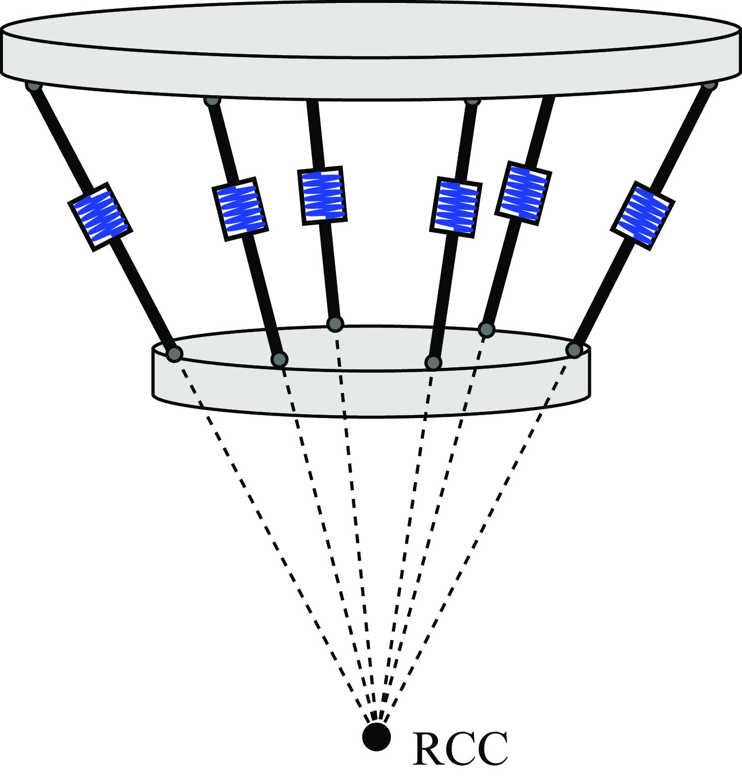
In compliance analysis, the term “center” has been used to describe different compliant behaviors. In the first usage [Reference Whitney1, Reference Whitney and Nevins28], the remote center of compliance (RCC) device was shown to be useful in robotic assembly. In ref. [Reference Kang, Hwang, Kim, Lee and Lee29], a controller was designed to update the RCC location so that a desired compliant motion was obtained for an insertion problem. An RCC device was designed to have symmetric elastic components intersecting at the center. Although the RCC location can be obtained with different elastic mechanisms [Reference Ciblak and Lipkin30] than that originally described [Reference Whitney and Nevins28], the stiffness matrix of the mechanisms can always be diagonalized at this location.
A second, more general way to define a center for a compliant behavior was presented in ref. [Reference Loncaric3]. It was proved that, for an arbitrary spatial stiffness matrix, there is a location in space at which the
 $3\times 3$
off-diagonal block matrices are symmetric. This location is unique for the generic case and was defined as the center of stiffness [Reference Loncaric3]. Similarly, the center of compliance was defined to be the location at which the compliance matrix has symmetric off-diagonal blocks. As such, every compliant behavior has a center of stiffness and a center of compliance. Although defined mathematically in terms of the stiffness and compliance matrices, the centers of stiffness and compliance were not interpreted in terms of elastic mechanisms that realize the behavior.
The relationship between the mathematically described behavior center location and the geometry of any mechanism that realizes the behavior was later identified for planar cases [Reference Huang and Schimmels16, Reference Huang and Schimmels31] and for spatial cases [Reference Huang and Schimmels32, Reference Huang and Schimmels33]. In [Reference White, Revzen, Thorne and Yim34], the concept of a center of stiffness was used in the analysis of modular robotic structures. In ref. [Reference Hao and Li35], the stiffness center concept was used to reduce parasitic rotations in the design of compliant mechanisms. In ref. [Reference Huang and Schimmels36], the spatial distributions of elastic components used to realize a compliance were shown to be restricted by the locations of the centers.
A third type of center that applies to all compliant behaviors is based on the set of wrench-compliant axes or twist-compliant axes [Reference Lipkin and Patterson37]. The geometric center of the three wrench-compliant axes (or the three twist-compliant axes) is defined as the center of elasticity [Reference Lipkin and Patterson37].
In general, the center of stiffness, the center of compliance, and the center of elasticity of a given compliant behavior are located at different points in space. In prior work [Reference Ciblak and Lipkin4], some properties of the centers were investigated. The focus of this paper is to develop a more complete understanding of the relationships between these three centers, especially the conditions when two centers are coincident and when all three are coincident.
1.2. Contribution of the paper
In some cases, the three conceptually different types of centers are coincident. In general, they are located at different points in space. For planar cases, the
 $3\times 3$
stiffness/compliance matrix can always be diagonalized (with a coordinate transformation) so the three centers are always coincident. Thus, for planar behavior, the terms center of stiffness, center of compliance, and center of elasticity can be used interchangeably (e.g., [Reference Wen, Shin, Seo and Lee18]). However, this is not true for generic spatial compliant behaviors. The main contributions of this paper are:
-
1. Identification of necessary and sufficient conditions for: a) the coincidence of any two centers, and b) the coincidence of all three centers;
-
2. Determination of the dimension of the space of compliant behaviors that have coincident centers for each combination;
-
3. Interpretation of the coincident center behaviors in terms of the geometry of an elastic mechanism having the simplest structure.
1.3. Overview
The paper analyzes general compliant behavior in terms of the “centers” associated with the behavior. Mathematical conditions for the coincidence of these centers are obtained. The dimension of the space of behaviors satisfying these conditions is identified. Physical interpretations of the coincident conditions are described in terms of the geometry of fully parallel or fully serial mechanisms that realize the behavior.
The paper is outlined as follows. Section 2 reviews the definitions and basic properties of the center of stiffness, the center of compliance, and the center of elasticity. In Section 3, necessary and sufficient conditions for the coincidence of the center of stiffness and center of compliance are presented. The implications of the coincidence conditions are also provided. In Section 4, the relations between the center of stiffness and the center of elasticity are presented and the coincident conditions for the two centers are identified. Equivalent relations are identified for the center of compliance and the center of elasticity. Physical interpretation of the coincidence conditions is described in terms of topologically simple mechanisms that realize the behavior. Section 5 investigates the case in which all three centers are coincident. The structure of the stiffness matrix in its normal form is identified and the physical interpretations of the center coincidence conditions are provided. In Section 6, numerical examples illustrate the application of the developed theory. Finally, a brief summary is provided in Section 7.
2. Centers of a compliant behavior
This section reviews the definitions of the different types of “centers” associated with a compliant behavior and some of their basic physical properties.
2.1. Center of stiffness and center of compliance
Consider a general symmetric stiffness matrix having the partitioned form:
 \begin{equation} \textbf {K} =\left [ \begin{array}{c@{\quad}c} \textbf {A} & \textbf {B} \\ \textbf {B}^T & \textbf {D} \end{array} \right ]. \end{equation}
It was shown [Reference Loncaric3] that, for the generic case, there is a unique location in space
 $C_k$
defined as the center of stiffness at which the behavior is described by a stiffness matrix with symmetric off-diagonal blocks (
 $\textbf {B} = \textbf {B}^T$
). The off-diagonal blocks can be diagonalized by a rotation transformation, which as defined in ref. [Reference Loncaric3] is the “normal form” of the stiffness matrix. Since the symmetry of the off-diagonal blocks in the stiffness matrix defines the location of the center of stiffness, the “normal form” of a stiffness matrix is used here (in a weak sense) to refer to a stiffness matrix that merely has symmetric off-diagonal block matrices [Reference Ciblak and Lipkin4, Reference Huang and Schimmels32]. Subsequent reference in this paper to the matrix “normal form” means that the off-diagonal block matrix
 $\textbf {B}$
is symmetric.
Similarly, for a symmetric compliance matrix partitioned in the form
 \begin{equation} \textbf {C} = \textbf {K}^{-1} =\left [ \begin{array}{c@{\quad}c} \textbf {E} & \textbf {G} \\ \textbf {G}^T & \textbf {H} \end{array} \right ], \end{equation}
the center of compliance was defined [Reference Loncaric3] as the location at which the
 $3\times 3$
off-diagonal block
 $\textbf {G}$
is symmetric, and a compliance matrix described at this location is referred to here as its “normal form.”
For
 $\textbf {K}$
and
 $\textbf {C}$
described in an arbitrary coordinate frame, the location of the stiffness center
 $\textbf {r}_k$
and the location of the compliance center
 $\textbf {r}_c$
relative to the frame used in originally describing the behavior are determined by [Reference Loncaric3]:
 \begin{align} \textbf {r}_k & = 2\left [ \textbf {A} - \mbox {trace}(\textbf {A})\textbf {I} \right ]^{-1} \textbf {b}, \end{align}
 \begin{align} \textbf {r}_c & = -2\left [ \textbf {H} - \mbox {trace}(\textbf {H})\textbf {I}\right ]^{-1}\textbf {g}, \end{align}
where
 $\textbf {I}$
is the
 $3\times 3$
identity matrix, and
 $\textbf {b}$
and
 $\textbf {g}$
are 3-vectors associated with the cross-product operations for the skew-symmetric parts of
 $\textbf {B}$
and
 $\textbf {G}$
:
 \begin{equation} \begin{aligned} \left [ \textbf {b}\times \right ] & = \frac {1}{2}(\textbf {B} - \textbf {B}^T), \\ \left [\textbf {g}\times \right ] & = \frac {1}{2} (\textbf {G} - \textbf {G}^T), \end{aligned} \end{equation}
where the cross-product matrix associated with an arbitrary vector
 $\textbf {v} = [v_1, v_2, v_3]^T$
is defined as:
 \begin{equation} \left [ \textbf {v}\times \right ] = \left [ \begin{array}{ccc} 0& -v_3 & v_2\\ v_3 & 0 & -v_1 \\ -v_2 & v_1& 0 \end{array} \right ]. \end{equation}
Note that the skew-symmetric matrix
 $\textbf {P}_v = \left [ \textbf {v}\times \right ]$
also defines a translation of a frame by
 $\textbf {v}$
.
Although the centers of stiffness and compliance are defined based on the mathematical form of the stiffness and compliance matrices, the physical significance of each of the two centers has been provided in terms of mechanisms having simple topology that realize the compliant behavior. It was shown [Reference Huang and Schimmels32] that for a given compliant behavior, a location
 $C_k$
is the center of stiffness if and only if the behavior can be realized by a parallel mechanism with all spring wrenches intersecting at
 $C_k$
; and a location
 $C_c$
is the center of compliance if and only if the behavior can be realized by a serial mechanism with all joint axes intersecting at
 $C_c$
.
In ref. [Reference Huang and Schimmels33], it was shown that, if any
 $n$
-spring parallel mechanism realizes an compliant behavior, the average distance from the stiffness center to the spring axes weighted by the spring stiffnesses is zero, i.e., if
 $k_i$
is the stiffness of spring
 $i$
and
 $\textbf {d}_i$
is the perpendicular distance from the stiffness center to the spring axis, then,
 \begin{equation} k_1\textbf {d}_1 + k_2\textbf {d}_2 + \ldots + k_n\textbf {d}_n = \textbf {0}. \end{equation}
If an
 $m$
-joint serial mechanism realizes a compliant behavior, the average distance from the compliance center to the joint axes weighted by the joint compliances is zero, i.e., if
 $c_i$
is the joint compliance of joint
 $i$
and
 $\textbf {r}_i$
is the perpendicular distance from the compliance center to the joint axis, then
 \begin{equation} c_1\textbf {r}_1 + c_2\textbf {r}_2 + \ldots + c_m\textbf {r}_m = \textbf {0}. \end{equation}
This property demonstrates the analogy between the center of stiffness (compliance) of a compliant behavior and the center of mass of a discrete mass system.
As shown in ref. [Reference Huang and Schimmels36], the distribution of spatial elastic components in a parallel mechanism used to realize a specified compliant behavior is restricted by a sphere. For example, if non-screw types of elastic components are used in a parallel mechanism to realize a given compliance, at least one component must be inside the sphere and at least one component must be outside the sphere. The radius of this sphere is determined by the traces of the block matrices in
 $\textbf {K}$
:
 \begin{equation} \rho _k = \sqrt \frac {\mbox {trace}(\textbf {D})} {\mbox {trace}(\textbf {A})}. \end{equation}
This sphere has a minimum radius when the behavior is described at the stiffness center. Similarly, the distribution of elastic joint axes in a serial mechanism used to realize a specified compliant behavior is restricted by a sphere in which its radius is determined by the traces of the block matrices in
 $\textbf {C}$
:
 \begin{equation} \rho _c = \sqrt \frac {\mbox {trace}(\textbf {E})} {\mbox {trace}(\textbf {H})}. \end{equation}
The sphere has a minimum radius when the behavior is described at the compliance center.
In the generic case, the centers of stiffness and compliance are not coincident.
2.2. Center of elasticity
An elastic screw axis was defined [Reference Dimentberg6] as a screw along which an applied wrench yields a pure translational (linear) deflection parallel to the axis. This screw axis was later [Reference Patterson and Lipkin8] referred to as a wrench-compliant axis. Its dual, the twist-compliant axis was defined [Reference Patterson and Lipkin8] to be a twist along which a deflection yields a pure couple about the axis.
Physical properties of these axes were also identified in ref. [Reference Patterson and Lipkin8]. The three wrench-compliant axes and the three twist-compliant axes were each shown to be readily calculated by an eigenvalue problem. If screw wrenches and screw eigentwists are expressed in Plücker’s ray and axis coordinates respectively, the three eigenwrenches
 $\textbf {w}_i$
are obtained by solving the eigenvalue problem:
 \begin{equation} \textbf {K}{\mathbf {\Gamma }} \textbf {w}_i = k_i \textbf {w}_i, \qquad i = 1, 2, 3, \end{equation}
and the three eigentwists
 $\textbf {t}_i$
are obtained from:
 \begin{equation} \textbf {C}{\mathbf {\Delta }} {\mathbf {\Gamma }}{\mathbf {\Delta }} \textbf {t}_i = c_i \textbf {t}_i, \qquad i = 1, 2, 3, \end{equation}
where
 $k_i \gt 0$
and
 $c_i\gt 0$
are scalars associated with translational stiffness and rotational compliance, and where the
 $6\times 6$
matrices
 $\mathbf {\Gamma }$
and
 $\mathbf {\Delta }$
are defined as:
 \begin{equation} {\mathbf {\Gamma }}= \left [ \begin{array}{c@{\quad}c} \textbf {I} & \textbf {0} \\ \textbf {0} & \textbf {0} \end{array} \right ], \qquad {\mathbf {\Delta }} = \left [ \begin{array}{c@{\quad}c} \textbf {0} & \textbf {I} \\ \textbf {I} & \textbf {0} \end{array} \right ], \end{equation}
where
 $\textbf {I}$
is the
 $3\times 3$
identify matrix.
It can be seen that the eigenvalue problem in Eq. (12) depends solely on the first three columns of the stiffness matrix
 $\textbf {K}$
. Thus, the eigenwrenches
 $\textbf {w}_i$
and the corresponding translational stiffnesses
 $k_i$
are determined by the two
 $3\times 3$
block matrices
 $\textbf {A}$
and
 $\textbf {B}^T$
of
 $\textbf {K}$
in Eq. (2).
Similarly, the eigenvalue problem in Eq. (13) depends solely on the last three columns of the compliance matrix
 $\textbf {C}$
. Thus, the eigentwists
 $\textbf {t}_i$
and the corresponding translational compliances
 $c_i$
are determined by the two
 $3\times 3$
block matrices
 $\textbf {H}$
and
 $\textbf {G}$
of
 $\textbf {C}$
in Eq. (3).
It was also shown [Reference Patterson and Lipkin8] that: (1) every full-rank compliant behavior has three orthogonal wrench-compliant axes (eigenwrenches) and three orthogonal twist-compliant axes (eigentwists); and (2) the wrench-compliant axes and twist-compliant axes are reciprocal, i.e., if
 $\textbf {w}_i$
and
 $\textbf {t}_i$
are the three eigenwrenches and eigentwists, then,
 \begin{equation} \textbf {w}_i^T\textbf {t}_j= 0, \qquad i, j = 1, 2, 3. \end{equation}
For a compliant behavior, the linear space spanned by the three eigenwrenches forms Ball’s 3-system
 ${\mathbb S}_w$
[Reference Ball5]. The three principal screws of
 ${\mathbb S}_w$
are reciprocal to each other, orthogonal to each other, and concurrent [Reference Ball5]. The intersection point of the principal screws is the center of the three wrench-compliant axes. For its dual, the linear space spanned by the three eigentwists forms Ball’s 3-system
 ${\mathbb S}_t$
. The three principal screws are reciprocal to each other, orthogonal to each other, and concurrent, and their intersection is the center of the twist-compliant axes. Since
 ${\mathbb S}_w$
and
 ${\mathbb S}_t$
are reciprocal, the two 3-systems
 ${\mathbb S}_w$
and
 ${\mathbb S}_t$
have the same center [Reference Ball5], which was defined in ref. [Reference Lipkin and Patterson37] as the center of elasticity.
As shown in ref. [Reference Ciblak and Lipkin4, Reference Lipkin and Patterson37], the location of the center of elasticity
 $C_e$
can be calculated using
 \begin{equation} \textbf {r}_e = \frac {1}{2}(\textbf {r}_1 + \textbf {r}_2 + \textbf {r}_3), \end{equation}
where
 $\textbf {r}_i$
is the vector from the coordinate origin perpendicular to the wrench- or twist-compliant axis. It can be seen from Eq. (16) that the center of elasticity is the center of a cuboid bounded by the three wrench-compliant axes or by the three twist-compliant axes. Thus, if the three eigenwrenches (eigentwists) meet at a point, the intersection point must be the center of elasticity.
Also, if the coordinate frame origin is at
 $C_e$
, the matrix product
 $\textbf {B}^T\textbf {A}^{-1}$
for the stiffness matrix
 $\textbf {K}$
in Eq. (2) or the matrix product
 $\textbf {G}\textbf {H}^{-1}$
for the compliance matrix
 $\textbf {C}$
in Eq. (3) is symmetric [Reference Ciblak38]. Thus, the skew-symmetric matrix associated with the location of the center of elasticity
 $\textbf {r}_e$
can be calculated by
 \begin{align} [\textbf {r}_e\times] & = \frac {1}{2}(\textbf {B}^T\textbf {A}^{-1}-\textbf {A}^{-1}\textbf {B}), \end{align}
 \begin{align} [\textbf {r}_e\times] & = \frac {1}{2}(\textbf {G}\textbf {H}^{-1}-\textbf {H}^{-1}\textbf {G}^T), \end{align}
and the vector indicating the location of the center of elasticity
 $\textbf {r}_e$
can be determined from
 $[\textbf {r}_e\times]$
using Eq. (7).
In general, the centers of stiffness, compliance, and elasticity are different locations in space. In the following, the physical significance of the coincidence of any two of the three centers is further investigated.
3. Coincidence of the center of stiffness and the center of compliance
In this section, the physical significance of the coincidence of the centers of stiffness and compliance is addressed. First, the mathematical conditions on the stiffness and compliance matrices for the two centers to be coincident are developed. Then, a physical interpretation of their coincidence is provided.
3.1. Coincident conditions in the normal form
Below, a necessary and sufficient condition on the stiffness matrix alone for the centers of stiffness and compliance to be coincident (and equivalently, one on the compliance matrix alone) is derived.
Consider a stiffness matrix
 $\textbf {K}$
expressed in its normal form:
 \begin{equation} \textbf {K} =\left [ \begin{array}{cc} \textbf {A} & \textbf {B} \\ \textbf {B} & \textbf {D} \end{array} \right ]. \end{equation}
Then based on their definitions, the centers of stiffness and compliance are coincident if and only if the inverse of
 $\textbf {K}$
,
 $\textbf {C}$
is also in its normal form, i.e., the matrix
 $\textbf {C} = \textbf {K}^{-1}$
has symmetric off-diagonal blocks:
 \begin{equation} \textbf {C} = \left [ \begin{array}{cc} \textbf {E} & \textbf {G} \\ \textbf {G} & \textbf {H} \end{array} \right ]. \end{equation}
As shown below, the coincidence of the two centers can be determined by conditions on just the stiffness matrix
 $\textbf {K}$
.
Proposition 1.
When a stiffness matrix
 $\textbf {K}$
is expressed in its normal form Eq. (
19
), the center of stiffness and the center of compliance are coincident if and only if the matrix
 $\textbf {D} \textbf {A}^{-1}\textbf {B}$
is symmetric, i.e.,
 \begin{equation} \textbf {D} \textbf {A}^{-1}\textbf {B} = \textbf {B} \textbf {A}^{-1}\textbf {D}. \end{equation}
Proof.
When
 $\textbf {K}$
is expressed in its normal form of Eq. (19) and the compliance matrix
 $\textbf {C} = \textbf {K}^{-1}$
is partitioned in the form of Eq. (3), the block matrices calculated using the Banachiewicz inversion formula [Reference Gallier39] are:
 \begin{align} \textbf {E} & = (\textbf {A} - \textbf {B}\textbf {D}^{-1}\textbf {B})^{-1}, \end{align}
 \begin{align} \textbf {H} & = (\textbf {D} -\textbf {B}\textbf {A}^{-1}\textbf {B})^{-1}, \end{align}
 \begin{align} \textbf {G} & = -\textbf {A}^{-1}\textbf {B}(\textbf {D} -\textbf {B}\textbf {A}^{-1}\textbf {B})^{-1}. \end{align}
If the centers of stiffness and compliance are coincident, the off-diagonal block matrix
 $\textbf {G}$
must be symmetric, i.e.,
 $\textbf {G} = \textbf {G}^T$
. To evaluate the symmetry of
 $\textbf {G}$
, consider the congruence transformation defined by
 \begin{equation} \tilde {\textbf {G}} = \textbf {H}^{-T}\textbf {G} \textbf {H}^{-1}. \end{equation}
Since a congruence transformation preserves the symmetry of a matrix,
 $\textbf {G}$
is symmetric if and only if
 $\tilde {\textbf {G}}$
is symmetric. Note that
 $\textbf {H}^{-1} = (\textbf {D} -\textbf {B}\textbf {A}^{-1}\textbf {B})$
is symmetric, and the transformed matrix
 $\tilde {\textbf {G}}$
is calculated by
 \begin{equation} \begin{aligned} \tilde {\textbf {G}} & = \textbf {H}^{-T}\textbf {G} \textbf {H}^{-1} \\ & = - (\textbf {D} -\textbf {B}\textbf {A}^{-1}\textbf {B}) \textbf {A}^{-1}\textbf {B}. \end{aligned} \end{equation}
Since
 $\textbf {A}$
,
 $\textbf {B}$
, and
 $\textbf {D}$
are symmetric,
 $\tilde {\textbf {G}}$
can be expressed as:
 \begin{align} \tilde {\textbf {G}} & = \textbf {B}\textbf {A}^{-1} \textbf {B}\textbf {A}^{-1}\textbf {B} -\textbf {D} \textbf {A}^{-1}\textbf {B} \nonumber \\ & = (\textbf {B}\textbf {A}^{-1})\textbf {B} (\textbf {B}\textbf {A}^{-1})^T -\textbf {D}\textbf {A}^{-1}\textbf {B}. \end{align}
Since the first matrix on the right side of Eq. (27) is symmetric,
 $\tilde {\textbf {G}}$
is symmetric if and only if the second matrix
 $\textbf {D}\textbf {A}^{-1}\textbf {B}$
is symmetric. Thus, the compliance matrix
 $\textbf {C}$
has a symmetric off-diagonal block matrix
 $\textbf {G}$
if and only if
 $\textbf {D} \textbf {A}^{-1}\textbf {B}$
is symmetric, which proves the proposition.
Note that since
 $\textbf {D}$
is symmetric,
 $\textbf {D}^{-1}$
must be symmetric. Then,
 \begin{equation*} \textbf {D}^ {-1} (\textbf {D}\textbf {A}^{-1}\textbf {B}) \textbf {D}^{-1} = \textbf {A}^{-1}\textbf {B}\textbf {D}^{-1}, \quad \qquad ( \textbf {A} \textbf {D}^ {-1} ) (\textbf {D}\textbf {A}^{-1}\textbf {B}) ( \textbf {A} \textbf {D}^ {-1} )^T = \textbf { B}\textbf {D}^{-1}\textbf {A}. \end{equation*}
Thus, the stiffness center and compliance center are coincident if and only if
 $\textbf {D}\textbf {A}^{-1}\textbf {B}$
(or equivalently
 $\textbf {A}^{-1}\textbf {B}\textbf {D}^{-1}$
or
 $\textbf {B}\textbf {D}^{-1}\textbf {A}$
) is symmetric.
Similarly, the coincidence of the two centers can alternately be determined based on conditions on just the compliance matrix
 $\textbf {C}$
. If the compliance matrix
 $\textbf {C}$
is expressed in its normal form of Eq. (20), then, the centers of stiffness and compliance are coincident if and only if
 $\textbf {G}\textbf {H}^{-1}\textbf {E}$
(or equivalently
 $\textbf { E}^{-1}\textbf {G}\textbf {H}^{-1}$
or
 $\textbf {G}\textbf {E}^{-1}\textbf {H}$
) is symmetric, i.e.,
 \begin{equation} \textbf {G}\textbf {H}^{-1}\textbf {E} = \textbf {E}\textbf {H}^{-1}\textbf {G} \quad \qquad \mbox {or} \qquad \textbf { E}^{-1}\textbf {G}\textbf {H}^{-1} =\textbf {H}^{-1}\textbf {G}\textbf {E}^{-1} \quad \qquad \mbox {or} \qquad \textbf {G}\textbf { E}^{-1}\textbf {H}= \textbf {H}\textbf {E}^{-1}\textbf {G}. \end{equation}
3.2. Implication of the coincidence of these two centers
The coincidence condition (21) applies when the block matrices are expressed in the normal form of
 $\textbf {K}$
in Eq. (19). If described in an arbitrary frame, a stiffness matrix has the form of Eq. (2):
 \begin{equation} \tilde {\textbf {K}} = \left [ \begin{array}{c@{\quad}c} \tilde {\textbf {A}} & \tilde {\textbf {B}} \\ \tilde {\textbf {B}}^T & \tilde {\textbf {D}} \end{array} \right ], \end{equation}
then
 $\tilde {\textbf {K}}$
can be transformed to its normal form by a translation defined by:
 \begin{equation} \textbf {K} = \left [ \begin{array}{c@{\quad}c} \textbf {I} & \textbf { 0} \\ \textbf {P}_k^T & \textbf {I} \end{array} \right ] \left [ \begin{array}{c@{\quad}c} \tilde {\textbf {A}} & \tilde {\textbf {B}} \\ \tilde {\textbf {B}}^T & \tilde {\textbf {D}} \end{array} \right ]\left [ \begin{array}{c@{\quad}c} \textbf {I} & \textbf { P}_k \\ \textbf {0}& \textbf {I} \end{array} \right ], \end{equation}
where, using the results of Eqs. (4) and (7),
 $\textbf {P}_k = [\textbf {r}_k\times]$
is the skew-symmetric matrix associated with the translation of the original frame to the behavior center of stiffness.
The block matrices
 $\textbf {A}$
,
 $\textbf {B}$
and
 $\textbf {D}$
in the normal form in Eq. (19) can be expressed:
 \begin{equation} \begin{aligned} \textbf {A} & = \tilde {\textbf {A}}, \\ \textbf {B} & = \tilde {\textbf {A}}\textbf {P}_k + \tilde {\textbf {B}}, \\ \textbf {D} & = \textbf {P}_k^T\tilde {\textbf {A}}\textbf {P}_k + \textbf {P}_k^T\tilde {\textbf {B}} + \tilde {\textbf {B}}^T\textbf {P}_k + \tilde {\textbf {D}}. \end{aligned} \end{equation}
Thus, the symmetry condition (21) can be expressed (less compactly) in terms of the block matrices in an arbitrary frame.
It is known that the collection of all
 $6\times 6$
symmetric matrices
 ${\mathbb S}_K$
is a 21-dimensional space. The symmetry condition (21) imposes three independent non-linear (high-order polynomial) conditions on the stiffness matrices. Thus the space of stiffness matrices that have coincident centers of stiffness and compliances is a 18-dimensional manifold in
 ${\mathbb S}_K$
.
It was shown [Reference Huang and Schimmels24, Reference Huang and Schimmels40] that an arbitrary compliant behavior can be realized by a unique parallel mechanism consisting of six screw springs or a unique serial mechanism consisting of six screw joints. Both the six screw springs and the six screw joints are determined by the six eigenscrews of the system. The six unit-eigenscrews
 $\hat {\textbf {w}}_i$
expressed in Plücker’s ray coordinates can be obtained by solving the eigenvalue problem associated with the stiffness matrix
 $\textbf {K}$
:
 \begin{equation} \textbf {K} {\mathbf {\Delta }} \hat {\textbf {w}}_i = \lambda _i \hat {\textbf {w}}_i, \end{equation}
or equivalently, the six unit-eigenscrews expressed in Plücker’s axis coordinates can be obtained by solving the eigenvalue problem associated with the compliance matrix
 $\textbf {C}$
:
 \begin{equation} \textbf {C} {\mathbf {\Delta }} \hat {\textbf {t}}_i = \gamma _i \hat {\textbf {t}}_i, \end{equation}
where
 $\mathbf {\Delta }$
is the
 $6\times 6$
matrix defined in Eq. (14), and where
 $\lambda _i$
and
 $\gamma _i= \lambda _i^{-1}$
are the compliant behavior eigenstiffnesses and eigencompliances, respectively. Note that the six eigenscrews
 $\hat {\textbf {w}}_i$
and
 $\hat {\textbf {t}}_i$
are the same screws expressed in different coordinates for which pairs satisfy
 $\hat {\textbf {w}}_i= {\mathbf {\Delta }}\hat {\textbf {t}}_i$
,
 $i = 1, 2, \ldots, 6$
. These eigenscrews are reciprocal to each other and are invariant under coordinate transformation. If
 $p_i$
is the pitch of eigenscrew
 $\textbf {e}_i$
 $(i = 1, 2, \ldots, 6)$
, then by the eigenscrew decomposition [Reference Huang and Schimmels24, Reference Huang and Schimmels40],
 \begin{align} \textbf {K} &= k_1\hat {\textbf {w}}_1\hat {\textbf {w}}_1^T + k_2\hat {\textbf {w}}_2\hat {\textbf {w}}_2^T + \ldots + k_6\hat {\textbf {w}}_6\hat {\textbf {w}}_6^T, \end{align}
 \begin{align} \textbf {C} & = c_1\hat {\textbf {t}}_1\hat {\textbf {t}}_1^T + c_2\hat {\textbf {t}}_2 \hat {\textbf {t}}_2^T + \ldots + c_6\hat {\textbf {t}}_6\hat {\textbf {t}}_6^T, \end{align}
where
 $k_i = {\lambda _i}/{2p_i} \gt 0$
and
 $c_i = {\gamma _i}/{2p_i}\gt 0$
are the corresponding spring rates and joint compliances for the parallel and serial mechanisms, respectively.
Equation (34) indicates that the behavior is realized by a 6-spring parallel mechanism that has the eigenstructure of the system: each spring has the spring wrench of an eigenscrew
 $\hat {\textbf {w}}_i$
. This mechanism has the characteristic that: a twist motion along a single spring wrench yields a wrench only along the same screw. Similarly, Eq. (35) indicates that the behavior is realized by a 6-joint serial mechanism for which each joint has the joint twist of an eigenscrew
 $\hat {\textbf {t}}_i$
. This serial mechanism has the characteristic that: a wrench along a single joint twist yields a motion twist only along the same screw. The six spring wrenches in the parallel mechanism and the six joint twists in the serial mechanism are the same screws and the two are dual elastic mechanisms [Reference Huang and Schimmels26].
Let
 $\textbf {d}_i$
be the vector from the stiffness center
 $C_k$
perpendicular to the eigenscrew axis
 $\hat {\textbf {w}}_i$
and
 $\hat {\textbf {t}}_i$
. If the two centers are coincident, by the results proved in [Reference Huang and Schimmels33]:
 \begin{equation} \sum _{i = 1}^{6}k_i\textbf {d}_i = \sum _{i = 1}^{6} \frac {\lambda _i}{2p_i} \textbf {d}_i = \textbf {0},\quad \qquad \sum _{i = 1}^{6}c_i\textbf {d}_i =\sum _{i = 1}^{6} \frac {1}{2\lambda _i p_i} \textbf {d}_i = \textbf {0}, \end{equation}
which implies
 \begin{equation} \sum _{i = 1}^{6} \frac {\lambda _i}{2p_i} \textbf {d}_i =\sum _{i = 1}^{6} \frac {1}{2\lambda _i p_i} \textbf {d}_i = \textbf {0}. \end{equation}
Thus, when the two centers are coincident, the weighted average distances (weighted by
 ${\lambda _i}/{p_i}$
for
 $\textbf {K}$
and by
 $1/(\lambda _ip_i)$
for
 $\textbf {C}$
) to the eigenscrews are both zero.
4. Coincidence of the center of stiffness (compliance) and the center of elasticity
In this section, the relationship between the center of stiffness (compliance) and the center of elasticity is investigated. First, the mathematical condition for the coincidence of the center of stiffness and the center of elasticity is derived. Next, the condition for the coincidence of the center of compliance and the center of elasticity is obtained by duality. Then, the physical significance of each coincidence case is interpreted in terms of a topologically simple mechanism that realizes the behavior.
4.1. Conditions for the coincidence of the centers of stiffness and elasticity
First, consider the coincidence of the center of stiffness and the center of elasticity. Recall that when a stiffness matrix
 $\textbf {K}$
is expressed in its normal form (Eq. (19)),
 $\textbf {B} = \textbf {B}^T$
. Then we have:
Proposition 2.1.
The center of stiffness and the center of elasticity are coincident if and only if the block matrices
 $\textbf {A}$
and
 $\textbf {B}$
of
 $\textbf {K}$
expressed in the normal form commute, i.e.,
 $\textbf {A}\textbf {B}= \textbf {B}\textbf {A}$
.
Proof.
First, consider the case in which it is known that
 $\textbf {A}$
and
 $\textbf {B}$
commute. Since both
 $\textbf {A}$
and
 $\textbf {B}$
in the normal form are symmetric, and
 $\textbf {A}$
and
 $\textbf {B}$
commute, there exists a unitary matrix
 $\textbf {U} = [\textbf {u}_1, \textbf {u}_2, \textbf {u}_3]$
such that
 \begin{equation} \textbf {A} = \textbf {U} {\mathbf \Lambda }_A \textbf {U}^T, \qquad \textbf {B} = \textbf {U} {\mathbf \Lambda }_{B}\textbf {U}^T, \end{equation}
where
 ${\mathbf \Lambda }_A= \mbox {diag}(k_1, k_2, k_3)$
and
 ${\mathbf \Lambda }_B = \mbox {diag}(\lambda _1, \lambda _2, \lambda _3)$
. Thus, each unit eigenvector of
 $\textbf {A}$
(vector
 $\textbf {u}_i$
) is also an eigenvector of
 $\textbf {B}$
. If the eigenvalues of
 $\textbf {A}$
are
 $k_i \gt 0$
and the eigenvalues of
 $\textbf {B}$
are
 $\lambda _i$
,
 \begin{equation} \textbf {A} \textbf {u}_i = k_i\textbf {u}_i, \qquad \textbf {B} \textbf {u}_i = \lambda _i\textbf {u}_i. \end{equation}
Consider the three unit wrenches defined by:
 \begin{equation} \textbf {w}_i =\left [ \begin{array}{c} \textbf {u}_i \\ \frac {1}{k_i}\textbf {B}\textbf {u}_i \end{array} \right ] = \left [ \begin{array}{c} \textbf {u}_i \\ \frac {\lambda _i}{k_i}\textbf {u}_i \end{array} \right ], \qquad i =1, 2, 3, \end{equation}
where the pitch of each wrench is:
 \begin{equation} p_i = \frac {\lambda _i}{k_i}, \qquad i = 1, 2, 3. \end{equation}
The structure of these three screws indicates that they pass through the origin of the frame (the center of stiffness) and satisfy the definition of an eigenwrench Eq. (12). Therefore, if
 $\textbf {A}$
and
 $\textbf {B}$
commute, the three wrenches
 $\textbf {w}_i$
defined in Eq. (40) are the eigenwrenches.
Now consider the case in which it is known that the center of stiffness and the center of elasticity are coincident. At the center of stiffness
 $\textbf {B}$
is symmetric, and at the center of elasticity
 $\textbf {A}^{-1}\textbf {B}$
is symmetric [Reference Ciblak38]. Then
 \begin{equation} \textbf {A}^{-1}\textbf {B} = \textbf {B}^T \textbf {A}^{-T} = \textbf {B}\textbf {A}^{-1}. \end{equation}
Multiplying Eq. (42) by
 $\textbf {A}$
from both sides yields the simple condition:
 \begin{equation} \textbf {A}\textbf {B} = \textbf {B}\textbf {A}. \end{equation}
Therefore,
 $\textbf {A}$
and
 $\textbf {B}$
commute.
Note that since in the normal form both
 $\textbf {A}$
and
 $\textbf {B}$
are symmetric,
 $\textbf {A}$
and
 $\textbf {B}$
commute if and only if
 $\textbf {A}\textbf {B}$
is symmetric. Thus, the necessary and sufficient condition for coincidence of the center of stiffness and the center of elasticity is that in the normal form
 $\textbf {A}\textbf {B}$
is symmetric.
It can be seen that when
 $\textbf {A}$
and
 $\textbf {B}$
in the normal form of
 $\textbf {K}$
commute (or equivalently
 $\textbf {A}\textbf {B}$
is symmetric), the three eigenwrenches
 $\textbf {w}_i$
in Eq. (40) are orthogonal and intersect at the center of stiffness. Thus, the eigenwrenches are the principal screws of the 3-system
 ${\mathbb S}_w$
, which is consistent with the result presented in [Reference Ciblak and Lipkin4] for the coincidence of the two centers. The simple condition in Proposition 2.1 allows one to determine the coincidence of the two centers without solving the eigenwrench problem and the corresponding principal screws.
In summary, we have
Corollary 2.1. The center of stiffness and the center of elasticity are coincident if and only if any one of the following equivalent statements holds.
-
1. The matrices
 $\textbf {A}$
and
$\textbf {B}$
in the normal form of
$\textbf {K}$
commute.
-
2. The matrix
$\textbf {A}\textbf {B}$
in the normal form is symmetric.
-
3. The three wrench-compliant axes intersect at a point.


4.2. Conditions for the coincidence of the centers of compliance and elasticity
The coincidence condition for the center of compliance and the center of elasticity can be obtained by duality. Consider a compliance matrix
 $\textbf {C}$
with the block matrices
 $\textbf {E}$
,
 $\textbf {G}$
and
 $\textbf {H}$
expressed in its normal form Eq. (20). Then,
Proposition 2.2.
The center f compliance and the center of elasticity are coincident if and only if the block matrices
 $\textbf {H}$
and
 $\textbf {G}$
of
 $\textbf {C}$
expressed in the normal form commute, i.e.,
 $\textbf {H}\textbf {G} = \textbf {G}\textbf {H}$
.
If
 $\textbf {H}$
and
 $\textbf {G}$
commute, they have the same set of eigenvectors
 $\textbf {v}_i$
:
 \begin{equation} \textbf {H} \textbf {v}_i = c_i\textbf {v}_i, \qquad \textbf {G} \textbf {v}_i = \gamma _i\textbf {v}_i, \qquad i = 1, 2, 3, \end{equation}
where
 $c_i \gt 0$
and
 $\gamma _i$
are scalars. The three eigentwists of the system are:
 \begin{equation} \textbf {t}_i =\left [ \begin{array}{c} \frac {\gamma _i}{c_i}\textbf {v}_i \\ \textbf {v}_i \end{array} \right ], \qquad i =1, 2, 3. \end{equation}
The three eigentwists are orthogonal and intersect at the center of compliance and thus are the three principal screws of the 3-system
 ${\mathbb S}_t$
. Similar to Corollary 2.1, we have:
Corollary 2.2. The center of compliance and the center of elasticity are coincident if and only if any one of the following equivalent statements holds.
-
1. The block matrices
$\textbf {G}$
and
$\textbf {H}$
in the normal form of
$\textbf {C}$
commute.
-
2. The matrix
$\textbf {H}\textbf {G}$
in the normal form is symmetric.
-
3. The three twist-compliant axes intersect at a point.


4.3. Implications of stiffness center (or compliance center) coincidence with the center of elasticity
Although only proved for the normal form of a stiffness matrix, the results can be applied to a
 $\textbf {K}$
matrix described in an arbitrary frame using Eq. (31). The coincidence condition (43) imposes three non-linear restrictions on the stiffness matrix described in an arbitrary frame. Thus, the space of all stiffness matrices that have coincident stiffness and elasticity centers is a 18-dimensional manifold within the 21-dimensional space of all stiffness matrices. The same is true for the space associated with compliance and elasticity center coincidence. The two 18-dimensional manifolds, however, do not, in general, correspond to the same compliant behaviors.
Below, the decomposition developed in ref. [Reference Huang and Schimmels32] for a stiffness matrix in its normal form is used for the case when the center of stiffness and the center of elasticity are coincident. This decomposition yields a unique concurrent parallel mechanism that realizes the behavior.
Consider the decomposition of the stiffness matrix:
 \begin{equation} \textbf {K} = \textbf {K}_w + \textbf {K}_t, \end{equation}
where
 \begin{equation} \textbf {K}_w = \left [ \begin{array}{cc} \textbf {A} & \textbf { B} \\ \textbf {B} & \textbf {B}\textbf {A}^{-1}\textbf {B} \end{array} \right ], \quad \qquad \textbf {K}_t = \left [ \begin{array}{cc} \textbf {0} & \textbf { 0} \\ \textbf {0} & \textbf {D} - \textbf {B}\textbf {A}^{-1}\textbf {B} \end{array} \right ]. \end{equation}
As shown in ref. [Reference Huang and Schimmels32], both
 $\textbf {K}_w$
and
 $\textbf {K}_t$
are PSD. Consider the eigenwrenches
 $\textbf {w}_i$
 $(i = 1, 2, 3)$
defined in Eq. (40). Using Eq. (39),
 $\textbf {K}_w$
can be expressed as
 \begin{equation} \textbf {K}_w = \sum _{i = 1}^3 k_i\textbf {w}_i\textbf {w}_i^T, \end{equation}
where
 $k_i \gt 0$
are the eigenvalues of
 $\textbf {A}$
. Thus
 $\textbf {K}_w$
can be realized with three screw springs with spring wrenches defined by the three eigenwrenches [Reference Huang and Schimmels25]. For
 $\textbf {K}_t$
, since
 $\textbf {Q} =\textbf {D} - \textbf {B}\textbf {A}^{-1}\textbf {B} \gt 0$
,
 $\textbf {K}_t$
can be realized with three torsional springs [Reference Huang and Schimmels25]. A unique realization is obtained if the three torsional springs are selected to be along the three eigenvectors
 $\textbf {v}_i$
of
 $\textbf {Q}$
. Using Eq. (23),
 $\textbf {Q}$
is the inverse of the lower diagonal block matrix
 $\textbf {H}$
in the compliance matrix in Eq. (20), i.e.,
 $\textbf {Q} = \textbf {H}^{-1}$
. Therefore,
 $\textbf {Q}$
and
 $\textbf {H}$
have the same eigenvectors that determine the directions of the eigentwists. Thus, in this unique realization, the axes of the three torsional springs are along the axes of the eigentwists.
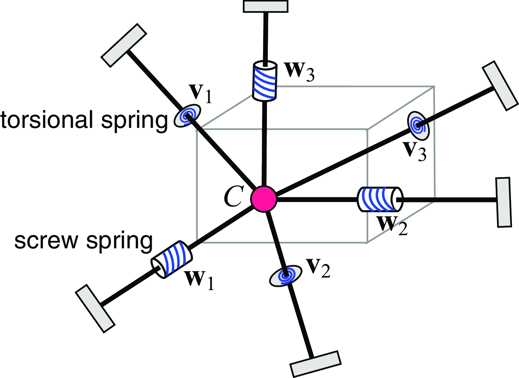
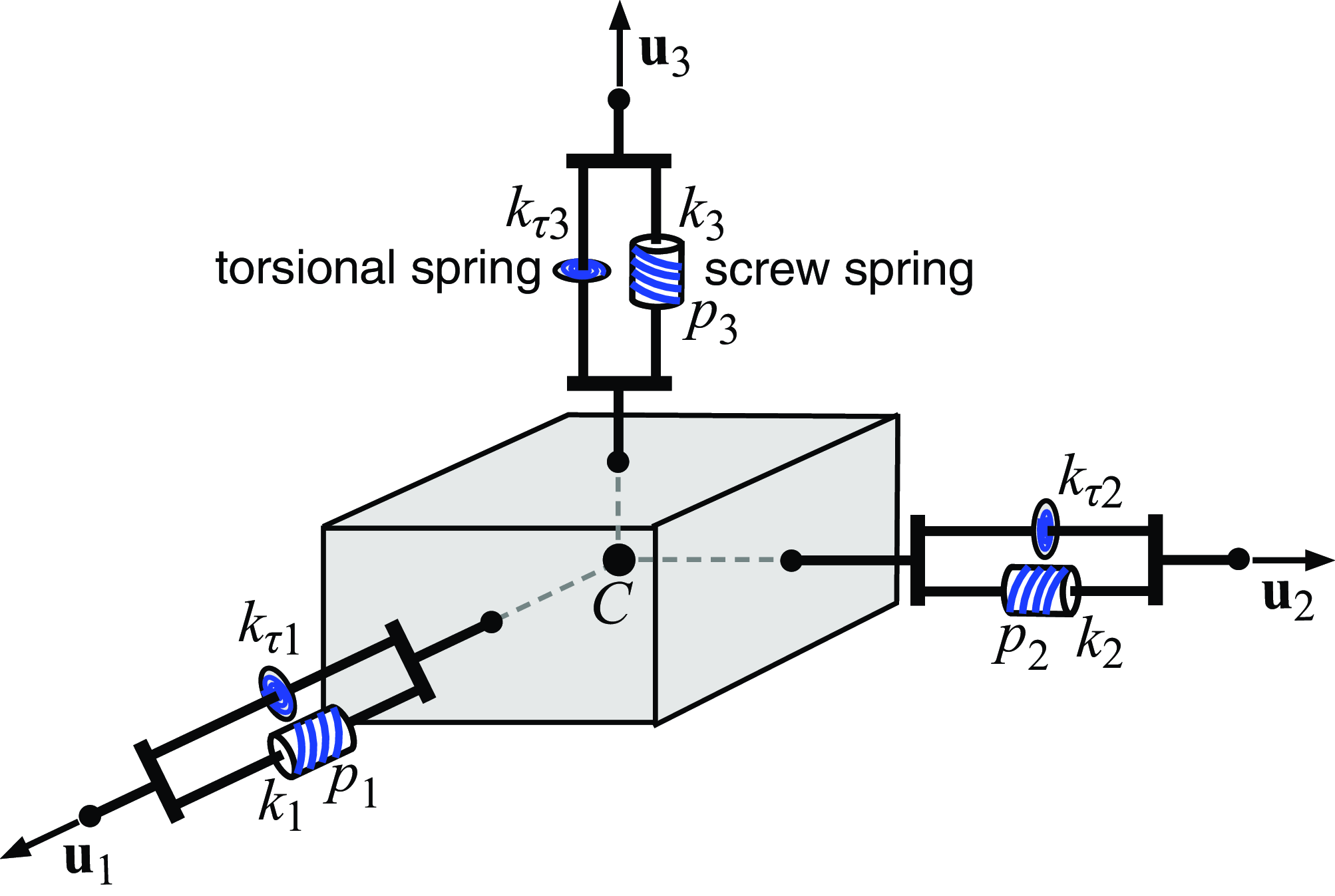
As such,
 $\textbf {K}$
is realized with three concurrent orthogonal screw springs along the three eigenwrenches and three orthogonal torsional springs along the three eigentwist axes as illustrated in Fig. 2. Note that the directions of the eigenwrenches are determined by the eigenvectors of
 $\textbf {A}$
and the directions of the eigentwists are determined by the eigenvectors of
 $\textbf {Q}$
. The directions of the eigenwrenches and eigentwists are not, in general, collinear. Also, it can be proved that if a compliant behavior is realized with three concurrent orthogonal screw springs and three torsional springs, the center of stiffness and the center of elasticity must be coincident and located at the intersection point of the six wrenches.
Physical interpretation of the coincidence of the center of stiffness and the center of elasticity. The two centers are coincident if and only if the behavior can be realized with a 6-spring parallel mechanism consisting of three concurrent and orthogonal screw springs along the axes of the eigenwrenches
 $\textbf {w}_i$
and three orthogonal torsional springs along the vectors
 $\textbf {v}_i$
, the directions of the three eigentwist axes.

Note that an eigenwrench could have zero pitch. When
 $\textbf {B}$
is not full rank, at least one eigenvalue
 $\lambda _i=0$
for which
 $\textbf {w}_i$
becomes a line vector and the corresponding screw spring becomes a line spring.
Since the three orthogonal screw springs are along the eigenwrenches, the corresponding spring wrenches are reciprocal. Thus, a screw motion (twist) along one screw spring axis has no influence on the other two screw springs. Since the three torsional spring axes are orthogonal, a pure rotation about one torsional spring axis has no influence on the other two torsional springs.
By duality, the centers of compliance and elasticity are coincident if and only if the behavior can be realized by a 6-joint serial mechanism that has three screw joints with orthogonal concurrent axes and three orthogonal prismatic joints.
5. Coincidence of all three centers
In this section, conditions for the coincidence of all three centers are addressed. First, a condition identifying when all three centers are collinear is derived. Then, a set of conditions for the coincidence of the three centers is obtained. In the subsequent analysis, it is shown that: (1) the eigenvalues of the
 $\textbf {A}^{-1}\textbf {B}$
matrix are the pitches of the eigenwrenches, and (2) the structure of the simplest normal form for
 $\textbf {K}$
depends on whether the pitch values are distinct or repeated. Thus, the coincidence conditions and their physical interpretations are developed separately for cases in which
 $\textbf {A}^{-1}\textbf {B}$
has distinct, 2, and 3 repeated eigenvalues.
5.1. Collinearity of the three centers
The collinearity of centers and coincidence of centers relate to the three eigenvectors associated with block matrices A, B and D in the normal form of K. The condition for collinearity is considered first.
Proposition 3.
If the block matrices
 $\textbf {A}$
,
 $\textbf {B}$
and
 $\textbf {D}$
in the normal form have a common eigenvector
 $\textbf {u}$
, then the center of stiffness, the center of compliance and the center of elasticity are collinear.
Proof.
Suppose the matrices
 $\textbf {A}$
,
 $\textbf {B}$
and
 $\textbf {D}$
have a common eigenvector
 $\textbf {u}$
and the corresponding eigenvalues are
 $k$
,
 $\lambda$
, and
 $\gamma$
, respectively. Then,
 \begin{equation} \textbf {A}\textbf {u} = k\textbf {u}, \qquad \textbf {B}\textbf {u} = \lambda \textbf {u}, \qquad \textbf {D}\textbf {u} = \gamma \textbf {u}. \end{equation}
As shown in Sec. 4.1, the wrench defined by
 \begin{equation} \textbf {w} = \left [ \begin{array}{c} \textbf {u} \\ \frac {1}{k}\textbf {B}\textbf {u}\end{array} \right ] = \left [ \begin{array}{c} \textbf {u} \\ \frac {\lambda }{k}\textbf {u} \end{array} \right ] \end{equation}
is an eigenwrench of
 $\textbf {K}$
. The eigenwrench has direction
 $\textbf {u}$
and passes through the center of stiffness. It was shown [Reference Ciblak and Lipkin4] that, if an eigenwrench passes through the center of stiffness, it must also pass through the center of elasticity. Thus, the eigenwrench
 $\textbf {w}$
in Eq. (50) passes through both the center of stiffness and the center of elasticity.
Now consider the compliance matrix
 $\textbf {C}$
in the partitioned form of Eq. (3). Using Eqs. (22)–(24), it can be proved (proof provided in Appendix A) that
 $\textbf {u}$
is also a common eigenvector of
 $\textbf {E}$
,
 $\textbf {H}$
and
 $\textbf {G}$
and the corresponding eigenvalues for the three matrices are:
 \begin{equation} \mu _E = \frac {\gamma }{k\gamma - \lambda ^2}, \quad \qquad \mu _H = \frac {k}{k\gamma -\lambda ^2}, \quad \qquad \mu _G = -\frac {\lambda }{k\gamma -\lambda ^2}. \end{equation}
Similarly, the twist in the form
 \begin{equation} \textbf {t} = \left [ \begin{array}{c} -{\frac {\lambda }{k}}\textbf {u} \\ \textbf {u}\end{array} \right ] \end{equation}
is an eigentwist of the behavior. Thus,
 $\textbf {t}$
passes through both the center of compliance and the center of elasticity.
Since the eigenwrench
 $\textbf {w}$
in Eq. (50) and the eigentwist
 $\textbf {t}$
in Eq. (52) are collinear, the axis of
 $\textbf {w}$
and the axis of
 $\textbf {t}$
each passes through the three centers, which proves the proposition.
In ref. [Reference Patterson and Lipkin9], a compliance axis is defined as a line for which: (1) a force along the line produces a parallel linear deformation, and (2) a rotational deformation about the line produces a parallel couple. It was shown [Reference Ciblak and Lipkin4] that, if a system has a compliant axis, the three centers must be collinear. The common eigenvector condition in Proposition 3 does not imply the existence of a compliant axis. However, as proved in Appendix B, if the system has a compliant axis, the block matrices
 $\textbf {A}$
,
 $\textbf {B}$
and
 $\textbf {D}$
in the normal form of
 $\textbf {K}$
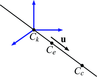
must have a common eigenvector. Thus, the collinear condition for the three centers in Proposition 3 is more general than that presented in ref. [Reference Ciblak and Lipkin4]. The line on which the three centers lie is in the direction of the common eigenvector
 $\textbf {u}$
as illustrated in Fig. 3.
Collinear condition for the three centers. If in the normal form of a stiffness matrix the four
 $3\times 3$
block matrices have a common eigenvector
 $\textbf {u}$
, the three centers lie on the line having direction
 $\textbf {u}$
.

It can be seen that if
 $\textbf {A}$
,
 $\textbf {B}$
and
 $\textbf {D}$
in the normal form of
 $\textbf {K}$
have two common eigenvectors, the three centers must be coincident. This establishes a sufficient condition for the coincidence of the three centers. Formally,
Corollary 3.
If the block matrices
 $\textbf {A}$
,
 $\textbf {B}$
and
 $\textbf {D}$
in the normal form have two common eigenvectors, then the center of stiffness, the center of compliance, and the center of elasticity are coincident.
Note that, since the block matrices
 $\textbf {A}$
,
 $\textbf {B}$
and
 $\textbf {D}$
are symmetric in the normal form, the three eigenvectors of each are orthogonal. Thus, if
 $\textbf {A}$
,
 $\textbf {B}$
and
 $\textbf {D}$
have two common eigenvectors, the third one is uniquely determined and must be the same for all three matrices. Therefore, if the three block matrices have two common eigenvectors, the three matrices must have the same set of eigenvectors. However, the condition that the three block matrices have the same eigenvectors is only a sufficient condition (and not necessary) for the three centers to be coincident. In the following, necessary and sufficient conditions for the coincidence of all three centers are developed.
5.2. Necessary and sufficient conditions for the coincidence of all three centers
The coincident conditions for the three centers can be obtained by combining the results presented in Sections 3 and 4. In general, we have:
Proposition 4. The centers of stiffness, compliance, and elasticity are coincident if and only if any one of the following statements holds.
-
1. The block matrices
$\textbf {A}$
and
$\textbf {B}$
in the normal form of
$\textbf {K}$
commute, and the block matrices
$\textbf {G}$
and
$\textbf {H}$
in the normal form of
$\textbf {C}$
commute.
-
2. The block matrices
$\textbf {A}$
and
$\textbf {B}$
in the normal form of
$\textbf {K}$
commute, and
$\textbf {B}\textbf {A}^{-1}\textbf {D}$
is symmetric.
-
3. The product
$\textbf {A}^{-1}\textbf {B}$
in the normal form of
$\textbf {K}$
is symmetric, and
$\textbf {B}\textbf {A}^{-1}\textbf {D}$
is symmetric.
-
4. The three wrench-compliant axes and the three twist-compliant axes intersect at one point.
-
5. The three wrench-compliant axes are the principal axes of
${\mathbb S}_w$
, and the three twist-compliant axes are the principal axes of
${\mathbb S}_t$
.


Note that the coincidence of all centers in general requires two sets of conditions, e.g., the conditions in Eq. (21) and the conditions in Eq. (43). As stated in Sections 3.2 and 4.2, Eqs. (21) and (43) each impose three independent restrictions on the stiffness matrix. Thus, the necessary and sufficient conditions in Proposition 4 impose a total of six independent restrictions on the stiffness matrix. Therefore, the space of compliant behaviors that have the three centers coincident is a 21
 $-$
6 = 15 dimensional manifold.
As shown in Section 4.1, when the center of stiffness and the center of elasticity are coincident,
 $\textbf {A}$
and
 $\textbf {B}$
in the normal of
 $\textbf {K}$
have the same set of eigenvectors and have three eigenwrenches
 $\textbf {w}_i$
in the form of Eq. (40). If
 $k_i$
and
 $\lambda _i$
are the eigenvalues of
 $\textbf {A}$
and
 $\textbf {B}$
associated with
 $\textbf { w}_i$
, since A and B can be simultaneously diagonalized by a rotation, the matrix
 $\textbf { A}^{-1}\textbf {B}$
has eigenvalues
 $\lambda _i/k_i$
 $(i = 1,2,3)$
which are the pitches of the eigenwrenches
 $\textbf {w}_i$
.
Although Proposition 4 provides a set of necessary and sufficient conditions for the coincidence of all three centers, these conditions, however, do not provide insight into the simplest stiffness normal form or the simplest mechanism that realizes the behavior. Since the algebraic multiplicity of the eigenvalues of
 $\textbf {A}^{-1}\textbf {B}$
indicates the number of repeated eigenwrench pitches, additional center coincidence conditions for the different multiplicity cases are derived and the corresponding different physical interpretations of the coincidence conditions are provided.
As stated in Proposition 4-(3), when the three centers are coincident, the
 $\textbf {A}^{-1}\textbf {B}$
matrix in the normal form must be symmetric and thus must have three real eigenvalues that may be distinct or repeated. The three possible multiplicity cases for these real eigenvalues are considered below.
5.2.1. Case I:
$\textbf {A}^{-1}\textbf {B}$
has three distinct eigenvalues

In this case, the three eigenwrenches have distinct pitches. This is the generic case since, if
 $\textbf {A}^{-1}\textbf {B}$
has distinct eigenvalues, then there exists an open neighborhood of
 $\textbf {K}$
such that
 $\textbf {A}^{-1}\textbf {B}$
has distinct eigenvalues for all matrices in the neighborhood, and the matrices of
 $\textbf {K}$
for which
 $\textbf {A}^{-1}\textbf {B}$
have distinct eigenvalues are dense in the space of all
 $6\times 6$
PSD matrices.
First we prove that if the three centers are coincident, then
 $\textbf {A}\textbf {D} = \textbf {D}\textbf {A}$
and
 $\textbf {D}\textbf{B} = \textbf {B}\textbf {D}$
, i.e., any two block matrices in the normal form of
 $\textbf {K}$
commute.
Since the three centers are coincident, by Proposition 4,
 $\textbf {A}$
and
 $\textbf {B}$
commute and have the same set of eigenvectors. Let
 $\textbf {U} = [\textbf {u}_1, \textbf {u}_2, \textbf {u}_3]$
be the orthogonal matrix where the
 $\textbf {u}_i$
are the eigenvectors of the two matrices, then
 \begin{equation} \textbf {A} = \textbf {U} {\mathbf \Lambda }_A \textbf {U}^T, \qquad \textbf {B} = \textbf {U} {\mathbf \Lambda }_B\textbf {U}^T, \end{equation}
where
 ${\mathbf \Lambda }_A = \mbox {diag}(k_1, k_2, k_3)$
and
 ${\mathbf \Lambda }_B =\mbox {diag}(\lambda _1, \lambda _2, \lambda _3)$
and
 $k_i$
and
 $\lambda _i$
are eigenvalues of
 $\textbf {A}$
and
 $\textbf {B}$
, respectively. Then,
 \begin{equation} \textbf {A}^{-1}\textbf {B} = \left ( \textbf {U}{\mathbf \Lambda }_A\textbf {U}^T\right )^{-1}\textbf {U}{\mathbf \Lambda }_B\textbf {U}^T = \textbf {U} {\mathbf \Lambda }_A^{-1}{\mathbf \Lambda }_B\textbf {U}^T, \end{equation}
where
 ${\mathbf \Lambda }_A^{-1}{\mathbf \Lambda }_B$
is diagonal:
 \begin{equation} {\mathbf \Lambda }_A^{-1}{\mathbf \Lambda }_B = \mbox {diag}\left (\frac {\lambda _1}{k_1}, \frac {\lambda _2}{k_2}, \frac {\lambda _3}{k_3}\right ). \end{equation}
It can be seen that each
 $\textbf {u}_i$
is an eigenvector of
 $\textbf {A}^{-1}\textbf {B}$
associated with eigenvalue
 ${\lambda _i}/{k_i}$
, i.e.,
 \begin{equation} \textbf {A}^{-1}\textbf {B} \textbf {u}_i = \frac {\lambda _i}{k_i} \textbf {u}_i. \end{equation}
As shown below,
 $\textbf {u}_i$
is also an eigenvector of
 $\textbf {D}$
. Since the three centers are coincident, combining Eqs. (21) and (43),
 \begin{equation} \textbf {B} \textbf {A}^{-1} \textbf {D} = \textbf {D}\textbf {A}^{-1}\textbf {B}, \qquad \textbf {A}^{-1} \textbf {B} = \textbf { B} \textbf {A}^{-1}, \end{equation}
yields
 \begin{equation} \textbf {A}^{-1}\textbf {B} \textbf {D} = \textbf {B} \textbf {A}^{-1} \textbf {D} = \textbf {D}\textbf {A}^{-1}\textbf {B}. \end{equation}
Thus,
 \begin{equation} \textbf {A}^{-1}\textbf {B} \textbf {D} \textbf {u}_i = \textbf {D} \textbf {A}^{-1}\textbf {B}\textbf {u}_i = \textbf {D} (\frac {\lambda _i}{k_i} \textbf {u}_i) = \frac {\lambda _i}{k_i} \textbf {D}\textbf {u}_i, \end{equation}
which means:
 \begin{equation} \textbf {A}^{-1}\textbf {B} (\textbf {D} \textbf {u}_i) = \frac {\lambda _i}{k_i} (\textbf {D}\textbf {u}_i). \end{equation}
Hence,
 $\textbf {D}\textbf {u}_i$
is an eigenvector of
 $\textbf {A}^{-1}\textbf {B}$
associated with eigenvalue
 ${\lambda _i}/{k_i}$
. Since
 $\textbf {A}^{-1}\textbf {B}$
has distinct eigenvalues, the eigenspace corresponding to each eigenvalue
 ${\lambda _i}/{k_i}$
is one dimensional and is spanned by the eigenvector
 $\textbf {u}_i$
. Therefore, there exists a constant
 $\gamma _i$
such that:
 \begin{equation} \textbf {D} \textbf {u}_i = \gamma _i\textbf {u}_i, \qquad i = 1, 2, 3, \end{equation}
which proves that each
 $\textbf {u}_i$
is an eigenvector of
 $\textbf {D}$
.
Since
 $\textbf {A}$
,
 $\textbf {B}$
and
 $\textbf {D}$
have the same set of eigenvectors
 $\textbf {U}$
, any two commute and the three matrices can be diagonalized simultaneously.
Now consider the compliance matrix
 $\textbf {C}=\textbf {K}^{-1}$
. Since the three centers are coincident,
 $\textbf {C}$
must be also in its normal form of Eq. (20). Below, it is shown that the set of eigenvectors of
 $\textbf {A}$
,
 $\textbf {U} = [\textbf {u}_1, \textbf {u}_2, \textbf {u}_3]$
, is also a set of eigenvectors of
 $\textbf {H}$
. In fact, from Eq. (23),
 \begin{equation} \textbf {H}^{-1} \textbf {u}_i = (\textbf {D} -\textbf {B}\textbf {A}^{-1}\textbf {B})\textbf {u}_i = (\gamma _i-\frac {\lambda _i^2}{k_i} )\textbf {u}_i. \end{equation}
Thus,
 $\textbf {u}_i$
is an eigenvector of
 $\textbf {H}^{-1}$
associated with eigenvalue
 $k_{\tau _i}$
defined by:
 \begin{equation} k_{\tau i} = \gamma _i-\frac {\lambda _i^2}{k_i} \gt 0, \qquad i = 1, 2, 3. \end{equation}
Because
 $\textbf {H}$
has the same eigenvectors as
 $\textbf {H}^{-1}$
,
 $\textbf {U} = [\textbf {u}_1, \textbf {u}_2, \textbf {u}_3]$
is a full set of eigenvectors of
 $\textbf {H}$
.
Since the direction of the eigentwists is along the eigenvectors of
 $\textbf {H}$
, the three eigenwrenches
 $\textbf {w}_i$
are parallel to the three eigentwists
 $\textbf {t}_i$
. Because
 $\textbf {w}_i$
and
 $\textbf {t}_i$
are reciprocal
 $(\textbf {w}_i^T\textbf {t}_i = 0)$
, they must have pitches with the same magnitude and opposite sign, i.e.,
 \begin{equation} \textbf {w}_i = \left [ \begin{array}{c} \textbf {u}_i\\[2pt] \frac {\lambda _i}{k_i}\textbf {u}_i \end{array} \right ], \quad \qquad \textbf {t}_i= \left [ \begin{array}{c} -{\frac {\lambda _i}{k_i}}\textbf {u}_i \\[2pt] \textbf {u}_i \end{array} \right ], \qquad i = 1, 2, 3. \end{equation}
It is known that if each of the eigenwrench and eigentwist pairs are parallel, then
 $\textbf {A}$
in
 $\textbf {K}$
and
 $\textbf {H}$
in
 $\textbf {C}$
have the same set of eigenvectors
 $\textbf {u}_i$
. As a consequence, the matrix
 $\textbf {D}$
in
 $\textbf {K}$
must also have the same eigenvectors
 $\textbf {u}_i$
. Thus, any two
 $3\times 3$
blocks in stiffness matrix
 $\textbf { K}$
commute. The four block matrices of the stiffness matrix can be diagonalized simultaneously, i.e., a rotational transformation of the stiffness matrix normal form can take the form:
 \begin{equation} \textbf {K} =\left [ \begin{array}{c@{\quad}c@{\quad}c@{\quad}c@{\quad}c@{\quad}c} k_1 & 0 & 0 & \lambda _1& 0 & 0 \\[3pt] 0 & k_2 & 0 & 0 & \lambda _2 & 0\\[3pt] 0 & 0 & k_3 & 0 & 0 & \lambda _3 \\[3pt] \lambda _1& 0 & 0 & \gamma _1 & 0 & 0 \\[3pt] 0 & \lambda _2 & 0 & 0 & \gamma _2 & 0 \\[3pt] 0 & 0 & \lambda _3 & 0 & 0 & \gamma _3 \end{array} \right ]. \end{equation}
Also, it is easy to show that if a stiffness matrix can be expressed in the form of Eq. (65), the three centers must be coincident. Thus for the generic case, the three centers are coincident if and only if the stiffness matrix can be expressed in the form of Eq. (65).
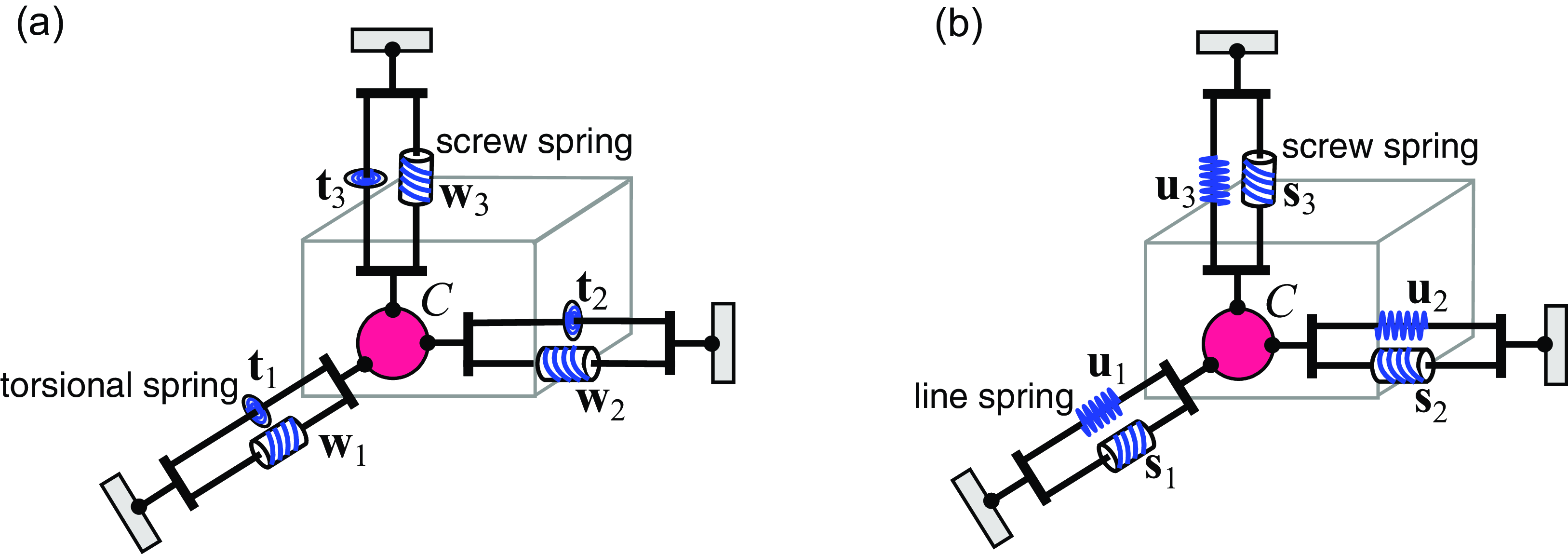
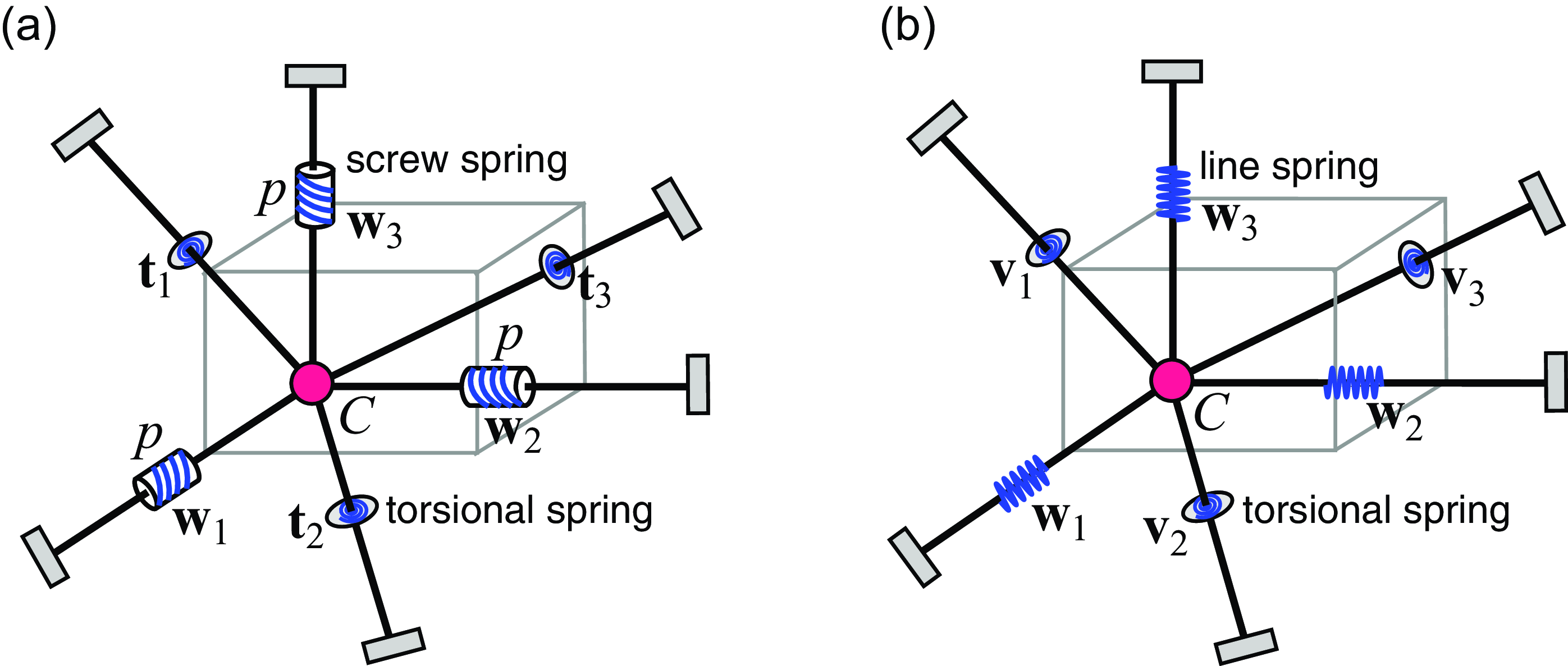
When the three centers are coincident, the compliant behavior can be realized with a specific mechanism based on the eigenwrenches and eigentwists. Since the eigenwrenches and eigentwists are collinear for this case, the compliant behavior can be realized by a parallel mechanism having three orthogonal and concurrent screw springs along the eigenwrenches and three orthogonal torsional springs in the same directions as the screw springs (as illustrated in Fig. 4a). The pitch of each screw spring equals the pitch of the corresponding eigenwrench.
Physical interpretation of coincidence of the three centers when the eigenwrench pitches are distinct. The behavior can be realized by a fully parallel mechanism with concurrent spring components. These components are either: (a) three orthogonal screw springs and three torsional springs along the axes of the eigenwrenches, or (b) three orthogonal screw springs and three line springs along the axes of eigenwrenches.

Similar to the decomposition of Eq. (46), the stiffness matrix in Eq. (19) can be alternately decomposed into the sum of two PSD components:
 \begin{equation} \textbf {K} = \left [ \begin{array}{cc} \textbf {A} - \textbf {B}\textbf {D}^{-1}\textbf {B} & \textbf { 0} \\[2pt] \textbf {0} & \textbf {0} \end{array} \right ] + \left [ \begin{array}{cc} \textbf {B}\textbf {D}^{-1}\textbf {B} & \textbf { B} \\[2pt] \textbf {B} & \textbf {D} \end{array} \right ] = \textbf {K}_l + \textbf {K}_s. \end{equation}
Since each
 $\textbf {u}_i$
is an eigenvector of
 $\textbf {A} - \textbf {B}\textbf {D}^{-1}\textbf {B}$
,
 $\textbf {K}_l$
can be realized with three line springs along
 $\textbf {u}_i$
. Denoting
 \begin{equation} \textbf {s}_i = \left [ \begin{array}{c} \textbf { u}_i \\[2pt] \frac {\gamma _i}{\lambda _i}\textbf {u}_i \end{array} \right ], \quad \qquad k_{si} = \frac {\lambda _i^2}{\gamma _i}, \qquad i = 1, 2, 3, \end{equation}
where
 $\gamma _i$
and
 $\lambda _i$
are the eigenvalues of
 $\textbf {D}$
and
 $\textbf {B}$
, respectively, then each screw wrench
 $\textbf {s}_i$
defines a screw spring passing through the center of stiffness and
 \begin{equation} \textbf {K}_s = \sum _{i =1}^3 k_{si} \textbf {s}_i\textbf {s}_i^T, \end{equation}
which means that
 $\textbf {K}_s$
is realized by the three screw springs defined by the spring wrenches
 $\textbf {s}_i$
. Thus, the stiffness
 $\textbf {K}$
is realized by three orthogonal concurrent screw springs and three concurrent line springs along the same axes (as illustrated in Fig. 4b). Note that although the three screw springs are along the axes of the eigenwrenches, they do not have the same pitches as the corresponding eigenwrenches. Also, it can be proved that if a stiffness is realized by a parallel mechanism consisting of three orthogonal concurrent screw springs and three line springs collinear to the axes of the three screw springs, the three centers must be coincident.
In summary, we have:
Proposition 4.1.
For a stiffness matrix in its normal form, if
 $\textbf {A}^{-1}\textbf {B}$
has distinct eigenvalues, then the center of stiffness, the center of compliance, and the center of elasticity are coincident if and only if any one of the following equivalent statements holds.
-
1. Every two of the four
$3\times 3$
block matrices in the normal form of
$\textbf {K}$
commute.
-
2. The four
$3\times 3$
block matrices in the normal form of
$\textbf {K}$
can be diagonalized simultaneously in the form of Eq. (
65
).
-
3. The compliant behavior can be realized with three orthogonal concurrent screw springs and three orthogonal torsional springs along the axes of the eigenwrenches.
-
4. The compliant behavior can be realized with three orthogonal concurrent screw springs and three orthogonal line springs along the axes of the eigenwrenches.


Note that, by Eqs. (23) and (24),
 \begin{equation} \textbf {A}^{-1}\textbf {B} = -\textbf {G}\textbf {H}^{-1}. \end{equation}
Thus,
 $\textbf {A}^{-1}\textbf {B}$
has distinct eigenvalues if and only if
 $\textbf {G}\textbf {H}^{-1}$
has distinct eigenvalues. By duality, results equivalent to these obtained for stiffness matrices and summarized in Proposition 4.1 hold for compliance matrices. When the matrix
 $\textbf {H}^{-1}\textbf {G}$
in the normal form of
 $\textbf {C}$
has three real and distinct eigenvalues, the three centers are coincident if and only if the compliance matrix can be expressed in the form in which each
 $3\times 3$
block matrix (
 $\textbf {E}$
,
 $\textbf {G}$
and
 $\textbf {H}$
) is diagonal. The behavior can be realized by a serial mechanism consisting of three concurrent screw joints along the axes of the eigenwrenches and three prismatic joints along the axes of the eigentwists.
5.2.2. Case II:
$\textbf {A}^{-1}\textbf {B}$
has two repeated eigenvalues

Suppose that
 $\textbf {A}^{-1}\textbf {B}$
has three eigenvalues
 $(p_1, p_2, p_3)$
with
 $p_1 = p_2 = p \neq p_3$
and suppose that
 $\textbf {u}_i$
is the unit eigenvector of
 $\textbf {A}^{-1}\textbf {B}$
associated with eigenvalue
 $p_i$
. The eigenspace associated with the repeated eigenvalue
 $p$
is the 2-dimensional linear space spanned by
 $\textbf {u}_1$
and
 $\textbf {u}_2$
and the eigenspace associated with
 $p_3$
is 1-dimensional linear space spanned by
 $\textbf {u}_3$
.
If the three centers are coincident,
 $\textbf {A}$
and
 $\textbf {B}$
commute and have the same eigenvectors
 $\textbf {u}_i$
. The stiffness matrix
 $\textbf {K}$
has eigenwrenches:
 \begin{equation} \textbf {w}_1 = \left [ \begin{array}{c} \textbf {u}_1 \\[3pt] p\textbf {u}_1 \end{array} \right ], \qquad \textbf {w}_2 = \left [ \begin{array}{c} \textbf {u}_2 \\[3pt] p\textbf {u}_2 \end{array} \right ], \qquad \textbf {w}_3 = \left [ \begin{array}{c} \textbf {u}_3 \\[3pt] p_3\textbf {u}_3 \end{array} \right ]. \end{equation}
Since
 $\textbf {u}_3$
is an eigenvector associated with a non-repeated eigenvalue, using the coincident condition
 $\textbf {B} \textbf {A}^{-1}\textbf {D} = \textbf {D} \textbf {A}^{-1}\textbf {B}$
,
 \begin{equation} \textbf {B} \textbf {A}^{-1} (\textbf {D} \textbf {u}_3) = \textbf {D} (\textbf {A}^{-1}\textbf {B}\textbf {u}_3) = p_3 (\textbf {D}\textbf {u}_3). \end{equation}
Thus
 $(\textbf {D} \textbf {u}_3)$
is an eigenvector of
 $\textbf {B} \textbf {A}^{-1}$
associated with eigenvalue
 $p_3$
, i.e.,
 $(\textbf {D} \textbf {u}_3)$
must be in the 1-dimensional eigenspace of
 $\textbf {B} \textbf {A}^{-1}$
spanned by
 $\textbf {u}_3$
. Therefore,
 $\textbf {u}_3$
is an eigenvector of
 $\textbf {D}$
and thus a common eigenvector of
 $\textbf {G}$
,
 $\textbf {E}$
and
 $\textbf {H}$
in the compliance matrix
 $\textbf {C}$
.
Since
 $\textbf {G} \textbf {H}^{-1} = -\textbf {A}^{-1}\textbf {B}$
, the compliant behavior has eigentwists:
 \begin{equation} \textbf {t}_1 = \left [ \begin{array}{c} -p\textbf {n}_1 \\[3pt] \textbf {n}_1 \end{array} \right ], \qquad \textbf {t}_2 = \left [ \begin{array}{c} -p\textbf {n}_2 \\[3pt] \textbf {n}_2 \end{array} \right ], \qquad \textbf {t}_3 = \left [ \begin{array}{c} -p_3\textbf {u}_3 \\[3pt] \textbf {u}_3 \end{array} \right ], \end{equation}
where
 $\textbf {n}_1$
and
 $\textbf {n}_2$
are arbitrary orthogonal unit eigenvectors of
 $\textbf {D}$
, each perpendicular to
 $\textbf { u}_3$
.
For this case, one of the eigentwists,
 $\textbf {t}_3$
is collinear with eigenwrench
 $\textbf {w}_3$
. The other two orthogonal eigentwists
 $\textbf {t}_1$
and
 $\textbf {t}_2$
have the same pitch
 $-p$
but are not necessarily collinear with
 $\textbf {w}_1$
and
 $\textbf {w}_2$
.
Conversely, it can be proved if the eigenwrenches and eigentwists have the forms of Eqs. (70) and (72) respectively with
 $p \neq p_3$
, then the three centers are coincident and
 $\textbf {A}^{-1}\textbf {B}$
has two repeated eigenvalues
 $p$
. In summary,
Proposition 4.2.
For a stiffness matrix in the normal form, if
 $\textbf {A}^{-1}\textbf {B}$
matrix has two repeated eigenvalues
 $p$
, then the three centers are coincident if and only if the eigenwrenches and eigentwists have the forms of Eqs. (
70
) and (
72
) respectively.
For this case, the behavior can be realized by a parallel mechanism having three orthogonal screw springs and three orthogonal torsional springs. One torsional spring is collinear with one screw spring. All springs intersect at a point as illustrated in Fig. 5.
Coincidence of the three centers when two eigenwrench pitches are repeated. The behavior can be realized by a fully parallel mechanism with six concurrent spring components of which three are orthogonal screw springs along the eigenwrenches and three are orthogonal torsional springs along the direction of eigentwists. One screw spring and one torsional spring are collinear in the direction
 $\textbf {u}_3$
.

Note that, although the decomposition of Eq. (66) applies to the stiffness matrix
 $\textbf {K}$
and yields a parallel mechanism consisting of three screw springs and three line springs all intersecting at the centers, only one screw spring and one line spring are required to be along the axis of the eigenwrench associated with the non-repeated eigenvectors. The directions of the other two screw springs and line springs are determined by the eigenvectors of
 $\textbf {B}\textbf {D}^{-1}\textbf {B}$
and
 $(\textbf {A} - \textbf {B}\textbf {D}^{-1}\textbf {B})$
respectively and are not necessarily along the axis of any eigenwrench or eigentwist.
Note that, when
 $\textbf {A}^{-1}\textbf {B}$
has repeated eigenvalues
 $p$
and associated eigenvectors
 $\textbf {u}_1$
and
 $\textbf { u}_2$
, the corresponding eigenspace is a 2-dimensional linear space spanned by
 $\textbf {u}_1$
and
 $\textbf {u}_2$
. Although
 $\textbf {D}\textbf {u}_1$
and
 $\textbf {D}\textbf {u}_2$
are in this eigenspace, they are not necessarily collinear with
 $\textbf {u}_1$
and
 $\textbf {u}_2$
respectively. Thus, only the eigenvector of
 $\textbf {A}$
and
 $\textbf {B}$
associated with the distinct (non-repeated) eigenvalue of
 $\textbf {A}^{-1}\textbf {B}$
is an eigenvector of
 $\textbf {D}$
. As such, although
 $\textbf { A}$
and
 $\textbf {B}$
can be diagonalized simultaneously by a rotation,
 $\textbf {D}$
may not be diagonalized by the same rotation. However, since
 $\textbf {D}$
has a common eigenvector with the other two matrices,
 $\textbf {D}$
can be partially diagonalized in the simplest general form:
 \begin{equation} \textbf {K} =\left [ \begin{array}{c@{\quad}c@{\quad}c@{\quad}c@{\quad}c@{\quad}c} k_1 & 0 & 0 & \lambda _1& 0 & 0 \\[3pt] 0 & k_2 & 0 & 0 & \lambda _2 & 0\\[3pt] 0 & 0 & k_3 & 0 & 0 & \lambda _3 \\[3pt] \lambda _1& 0 & 0 & d_{11} & d_{12} & 0 \\[3pt] 0 & \lambda _2 & 0 & d_{12} & d_{22} & 0 \\ 0 & 0 & \lambda _3 & 0 & 0 & \gamma _3 \end{array} \right ], \end{equation}
where
 $k_i$
and
 $\lambda _i$
must satisfy:
 \begin{equation} \frac {\lambda _1}{k_1} = \frac {\lambda _2}{k_2} \neq \frac {\lambda _3}{k_3}. \end{equation}
It can be seen that, for Case II, the three centers are coincident if and only if the stiffness matrix can be expressed in the form of Eq. (73) with restriction of Eq. (74).
Since
 $\textbf {A}^{-1}\textbf {B}$
and
 $\textbf {G}\textbf {H}^{-1}$
in the normal forms have the same eigenvalues, when
 $\textbf { A}^{-1}\textbf {B}$
has two repeated eigenvalues,
 $\textbf {G}\textbf {H}^{-1}$
must have the same two repeated eigenvalues. By duality, results equivalent to those obtained for a stiffness matrix presented in Proposition 4.2 hold for a compliance matrix for which the normal form takes the form of Eq. (73). The behavior can be realized by a serial mechanism having three orthogonal concurrent screw joints and three orthogonal prismatic joints. One prismatic joint axis is collinear with one screw joint axis.
5.2.3. Case III:
$\textbf {A}^{-1}\textbf {B}$
has three repeated eigenvalues

For this case, the three eigenwrenches have the same pitch. First, we prove that, if
 $\textbf {A}^{-1}\textbf {B}$
has three repeated eigenvalues and the center of stiffness and the center of elasticity are coincident, then the center of compliance must be located at the same point and thus three centers must be coincident. Using Eq. (40), the coincidence of the centers of stiffness and elasticity requires that the matrix
 $\textbf {A}^{-1}\textbf {B}$
be symmetric. Since
 $\textbf {A}^{-1}\textbf {B}$
has three repeated eigenvalues, in an appropriate coordinate frame, it can be expressed as
 \begin{equation} \textbf {A}^{-1}\textbf {B} = \textbf {B}\textbf {A}^{-1} = p \textbf {I}. \end{equation}
Since
 \begin{equation} \textbf {D}\textbf {A}^{-1}\textbf {B} = p \textbf {D} = \textbf {B} \textbf {A}^{-1}\textbf {D}, \end{equation}
condition (21) is satisfied and thus the centers of stiffness and compliance are coincident. Therefore, the three centers must be coincident.
From Eq. (75),
 $\textbf {B}$
can be expressed as:
 \begin{equation} \textbf {B} = p\textbf {A}. \end{equation}
If
 $k_i$
and
 $\textbf {u}_i$
are an eigenvalue and the corresponding eigenvector of
 $\textbf {A}$
, the three eigenwrenches are:
 \begin{equation} \textbf {w}_i = \left [ \begin{array}{c} \textbf {u}_i \\[3pt] \frac {1}{k_i}\textbf {B}\textbf {u}_i \end{array} \right ] = \left [ \begin{array}{c} \textbf {u}_i \\[3pt] \frac {1}{k_i}p \textbf {A}\textbf {u}_i \end{array} \right ] = \left [ \begin{array}{c} \textbf {u}_i \\[3pt] p\textbf {u}_i \end{array} \right ]. \end{equation}
Thus, the three eigenwrenches have the same pitch and meet at the center of stiffness.
Conversely, if the three eigenwrenches are concurrent and have the same pitch, then the matrix
 $\textbf {A}^{-1}\textbf {B}$
has three repeated eigenvalues and the three centers must be coincident. For this case, although the three eigentwists intersect at the same center, they are not necessarily collinear with the three eigenwrenches. Using the same process used for the eigenwrenches, it can be proved that the three eigentwists have the same pitch,
 $-p$
. A physical interpretation of the compliant behavior in terms of realization is: the stiffness matrix is realized with three orthogonal concurrent screw springs of the same pitch and three torsional springs as illustrated in Fig. 6a.
A special case is that
 $\textbf {A}^{-1}\textbf {B}$
has three zero eigenvalues. For this case,
 $\textbf {B} = \textbf {0}$
and the translation and rotation aspects of the behavior are completely decoupled. The three centers are coincident. The three eigenwrenches become three zero-pitch wrenches (pure forces) intersecting at the center and the three eigentwists become three zero-pitch twists (pure rotations) intersecting at the center. The eigenwrenches and eigentwists are not necessarily in the same directions. The compliant behavior can be realized with three concurrent orthogonal line springs and three orthogonal torsional springs as illustrated in Fig. 6b.
Coincidence of the three centers when three eigenwrench pitches are repeated. The behavior can be realized by a fully parallel mechanism with concurrent spring components: (a)
 $p \neq 0$
, three orthogonal screw springs along the eigenwrenches have the same pitch
 $p$
and three orthogonal torsional springs are along the directions of the eigentwists. (b)
 $p =0$
, three orthogonal line springs in the directions of the eigenwrenches and three orthogonal torsional springs in the directions of the eigentwists.

In summary:
Proposition 4.3.
For a stiffness matrix in its normal form, if
 $\textbf {A}^{-1}\textbf {B}$
has three repeated eigenvalues
 $p$
, then the three centers are coincident if and only if any one of the following statements is true.
-
1. The centers of stiffness and elasticity are coincident.
-
2. The centers of compliance and elasticity are coincident.
-
3. The three eigenwrenches are concurrent and have the same pitch
$p$
. -
4. The three eigentwists are concurrent and have the same pitch
$-p$
.


Using the same analysis for Case II, when
 $\textbf {A}^{-1}\textbf {B}$
has three repeated eigenvalues,
 $\textbf {D}$
does not necessarily have a common eigenvector with
 $\textbf {A}$
and
 $\textbf {B}$
, Thus, in general, the block matrices
 $\textbf {A}$
,
 $\textbf {B}$
and
 $\textbf {D}$
cannot be diagonalized simultaneously by a rotation. The simplest general form of a Case III
 $\textbf {K}$
in the normal form is:
 \begin{equation} \textbf {K} =\left [ \begin{array}{c@{\quad}c@{\quad}c@{\quad}c@{\quad}c@{\quad}c} k_1 & 0 & 0 & \lambda _1& 0 & 0 \\[3pt]0 & k_2 & 0 & 0 & \lambda _2 & 0\\[3pt]0 & 0 & k_3 & 0 & 0 & \lambda _3 \\[3pt]\lambda _1& 0 & 0 & d_{11} & d_{12} & d_{13} \\[3pt]0 & \lambda _2 & 0 & d_{12} & d_{22} & d_{23} \\[3pt]0 & 0 & \lambda _3 & d_{13} & d_{23} & d_{33} \end{array} \right ], \end{equation}
where
 $k_i$
and
 $\lambda _i$
satisfy:
 \begin{equation} \frac {\lambda _1}{k_1} = \frac {\lambda _2}{k_2} = \frac {\lambda _3}{k_3}. \end{equation}
A necessary and sufficient condition for a Case III stiffness matrix to have the three centers coincident is that the stiffness matrix can be expressed in the form of Eq. (79) with restriction of Eq. (80).
Note that although the mechanism shown in Fig. 6a for three coincident centers has the same geometry as the mechanism shown in Fig. 2 for two coincident centers, the three screw springs associated with the eigenwrenches in Fig. 6a are further constrained to have the same pitch.
Similar to Cases I and II, equivalent results hold for a compliance matrix
 $\textbf {C}$
in its normal form for which
 $\textbf { G}\textbf {H}^{-1}$
has three repeated eigenvalues. If the
 $\textbf {G}\textbf {H}^{-1}$
matrix in the normal form of
 $\textbf {C}$
has 3 repeated eigenvalues, the normal form can be transformed to the simplest form of Eq. (79). The behavior can be realized by a serial mechanism having three orthogonal concurrent screw joints with the same pitch and three orthogonal prismatic joints.
5.3. Discussion
Below, properties of stiffness matrixes that have diagonal block matrices and those that have completely diagonal normal form are provided.
5.3.1. Block diagonal matrices
It is easy to see that, when the normal form block matrices
 $\textbf {A}$
,
 $\textbf {B}$
and
 $\textbf {D}$
of a stiffness matrix are each diagonal (in the form of Eq. (65)), the three centers must be coincident. A necessary and sufficient condition for these block matrices to be diagonalized is that any two block matrices in the normal form commute. In Case I of Sec. 5.2.1, when
 $\textbf {A}^{-1}\textbf {B}$
has distinct eigenvalues, the coincidence of the three centers ensures that any two block matrices in the normal form commute. Thus, for this case, all three
 $3\times 3$
block matrices can always be diagonalized simultaneously. This is the most general (generic) case.
If
 $\textbf {A}^{-1}\textbf {B}$
has repeated eigenvalues (Cases II and III), the coincidence conditions do not ensure that
 $\textbf { A}$
and
 $\textbf {D}$
commute. Thus, in general, the stiffness matrix takes the form of Eq. (73) or (79) and the block matrices cannot be simultaneously diagonalized by a rotation. However, in the unlikely case that,
 $\textbf {A}$
and
 $\textbf {D}$
commute (and only this case) the stiffness matrix can be expressed in the form of Eq. (65). Here are two examples:
 \begin{equation} \textbf {K}_1 = \left [ \begin{array}{c@{\quad}c@{\quad}c@{\quad}c@{\quad}c@{\quad}c} 1 & 0 & 0 & -1 & 0 & 0 \\[3pt]0 & 3 & 0 & 0 & 1 & 0\\[3pt]0 & 0 & 2 & 0 & 0 & -2\\[3pt] -1& 0 & 0 & 8 & 0 & 0 \\[3pt] 0 & 1 & 0 & 0 & 9 & 0 \\[3pt] 0 & 0 & -2 & 0 & 0 & 5\end{array} \right ], \quad \qquad { \bf K}_2= \left [ \begin{array}{c@{\quad}c@{\quad}c@{\quad}c@{\quad}c@{\quad}c} 1 & 0 & 0 & 1& 0 & 0 \\[3pt] 0 & 2& 0 & 0 & 2 & 0\\[3pt] 0 & 0 & 3 & 0 & 0 & 3 \\[3pt] 1& 0 & 0 & 8 & 0 & 0 \\[3pt] 0 & 2 & 0 & 0 & 9 & 0 \\[3pt] 0 & 0 & 3 & 0 & 0 & 10 \end{array} \right ]. \end{equation}
For
 $\textbf {K}_1$
, the matrix
 $\textbf {A}^{-1}\textbf {B}$
has two repeated eigenvalues
 $-1$
. For
 $\textbf {K}_2$
, the matrix
 $\textbf {A}^{-1}\textbf {B}$
has three repeated eigenvalues
 $1$
. Both matrices have diagonal block matrices.
5.3.2. The remote center of compliance and the three centers
An interesting class of compliant behaviors is the set of stiffness matrices that can be completely diagonalized in the normal form. These behaviors are associated with the “remote center of compliance” (RCC) devices [Reference Whitney and Nevins28] that have been widely used in robotic manipulation. A commercial RCC device is a parallel compliant mechanism having symmetric concurrent elastic components similar to that illustrated in Fig. 7. The intersection of these axes is the “center” [Reference Whitney and Nevins28]. When the coordinate frame is placed at this location, both the stiffness and the compliance matrix are diagonal.
Remote center of compliance of a compliant behavior. An RCC device is a parallel mechanism with all elastic component axes intersecting at a point. In its normal form, the stiffness matrix can be diagonalized. This occurs only if all three centers are coincident and the RCC is located at the coincident centers.

It can be seen that an RCC is a special case of coincident centers of stiffness, compliance, and elasticity. It can be proved that an RCC-like behavior exists if and only if in the normal form of stiffness matrix in Eq. (19), the block matrices satisfy: (1)
 $\textbf {B} = \textbf {0}$
, and (2)
 $\textbf {A}$
and
 $\textbf {D}$
commute. The first condition imposes six constraints and the second imposes three constraints on the entries of a stiffness matrix. As such, the space of compliant behaviors associated with an RCC is a
 $21-9 = 12$
dimensional manifold in the 21-dimensional space of stiffness matrices. Similar conditions hold for compliance matrices in the normal form. Therefore, the RCC concept commonly referenced in robotic manipulation tasks only applies to a very small set of compliant behaviors.
5.3.3. Summary of results for coincidence of all three centers
The results presented in Proposition 4 are necessary and sufficient conditions for the three centers to be coincident. These conditions are for all compliant behaviors but provide little physical insight into the associated behaviors. The axes of eigenwrenches and eigentwists, the mathematical structure of the stiffness normal form, and the geometry of the simplest mechanism that realizes the behavior are based on the number of repeated eigenvalues of
 $\textbf {A}^{-1}\textbf {B}$
(which indicates the number of the repeated eigenwrench pitches) provide that physical insight. The results are summarized in Table I.
Summary of the results for coincident centers of stiffness, compliance, and elasticity.

As previously stated, Case I is the generic case. Thus, almost all compliant behaviors that have three coincident centers fall into this category. As illustrated in Fig. 4a, a Case I compliant behavior is characterized by a concurrent 6-spring parallel mechanism. Since the three screw springs and the three torsional springs are along the directions of the eigenwrenches, a screw motion (twist) along one screw wrench only causes a wrench in the direction of that screw axis (no influence on springs in the other two directions). The direction of the maximum (minimum) translational stiffness is along the axis of the eigenwrench for which the stiffness of the screw spring is the maximum (minimum). As such, the extremal properties of the behavior are clearly identified by the mechanism. Similarly, the behavior can also be interpreted in terms of the mechanism illustrated in Fig. 4b.
6. Examples
In this section, two numerical examples are provided to illustrate the application of the theory presented in this paper.
6.1. Example 1
A stiffness matrix used in ref. [Reference Cutkosky and Kao41] for inserting a rivet into a hole was selected as the first example. The stiffness matrix expressed in the selected global frame in the partitioned form of Eq. (3) is given by:
 \begin{equation*} \tilde {\textbf {A}} = \left [ \begin{array}{c@{\quad}c@{\quad}c} 2490 & 0 & 0 \\[3pt] 0 & 28900 & 0 \\[3pt] 0 & 0 & 61610 \end{array} \right ], \qquad \tilde {\textbf {B}}= \left [ \begin{array}{c@{\quad}c@{\quad}c} 0 & 258 & 0 \\[3pt]191 & 0 & 0 \\[3pt]0 & 0 & 0 \end{array} \right ], \qquad \tilde {\textbf {D}} = \left [ \begin{array}{c@{\quad}c@{\quad}c} 22 & 0 & 0 \\[3pt] 0 & 37 & 0 \\[3pt] 0 & 0 & 35 \end{array} \right ]. \end{equation*}
Using Eq. (4), the location of the stiffness center
 $C_k$
relative to the original frame is calculated to be:
 \begin{equation*} \tilde {\textbf {r}}_k = [0, \, 0, \, 0.0021]^T. \end{equation*}
When described at the stiffness center
 $C_k$
, the stiffness matrix has the normal form of Eq. (19) (having symmetric off-diagonal blocks
 $\textbf {B} = \textbf {B}^T$
):
 \begin{equation*} \textbf {A} = \left [ \begin{array}{ccc} 2490 & 0 & 0 \\0 & 28900 & 0 \\ 0 & 0 & 61610 \end{array} \right ], \quad \textbf {B} = \left [ \begin{array}{ccc} 0 & 252.6853 & 0 \\252.6853& 0 &0\\0 & 0 & 0 \end{array} \right ], \quad \textbf {D} = \left [ \begin{array}{ccc} 22.9470 & 0 & 0 \\ 0 & 35.9100 & 0 \\ 0 & 0 & 35 \end{array} \right ]. \end{equation*}
Since neither
 $\textbf {D}\textbf {A}^{-1}\textbf {B} = \textbf {B}\textbf {A}^{-1}\textbf {D}$
(Eq. (21)) nor
 $\textbf {A}\textbf {B} = \textbf {B}\textbf {A}$
(Eq. (43)) is satisfied for the block matrices
 $\textbf {A}$
,
 $\textbf {B}$
and
 $\textbf {D}$
, no two centers are coincident. The three matrices, however, do have a common eigenvector:
 \begin{equation*} \textbf {u} = [ 0, \, 0, \,1 ]^T. \end{equation*}
Hence the three centers must be located on the
 $z$
-axis. In the frame at the center of stiffness, the locations of the center of compliance and the center of elasticity are calculated using Eqs. (4) and (17) to be:
 \begin{equation*} \textbf {r}_c = [0, \, 0, \, 0.0650 ]^T, \quad \qquad \textbf {r}_e = [ 0, \, 0, \, 0.0464]^T, \end{equation*}
which confirms that the three centers are collinear.
In the original frame, the three centers are located at
 \begin{equation*} \tilde {\textbf {r}}_k = [0,\, 0, \, 0.0021 ]^T, \quad \qquad \tilde {\textbf {r}}_c = [ 0, \, 0, \, 0.0671]^T, \quad \qquad \tilde {\textbf {r}}_e = [0, \, 0, \, 0.0485]^T. \end{equation*}
6.2. Example 2
Consider a stiffness matrix in its normal form having block matrices:
 \begin{equation*} \begin{aligned} \textbf {A} & = \left [ \begin{array}{c@{\quad}c@{\quad}c} 2.1904 & 0.0960 & 0.4512 \\[3pt] 0.0960 & 3.2752 & -0.5280 \\[3pt] 0.4512 & -0.5280 & 3.5344\end{array} \right ], \qquad \textbf {B} = \left [ \begin{array}{c@{\quad}c@{\quad}c} -1.5754 & 0.7718 & 0.6627 \\[3pt] 0.7718 & 0.2282 & 0.6965 \\[3pt] 0.6627 & 0.6965 & -0.6528 \end{array} \right ], \\[3pt] \textbf {D} & = \left [ \begin{array}{c@{\quad}c@{\quad}c} 4.2342 & 0.6759 & 0.2115 \\[3pt] 0.6759 & 4.9530 & 1.2245 \\[3pt] 0.2115 & 1.2245 & 3.8128 \end{array} \right ]. \end{aligned} \end{equation*}
In this example, the matrix
 $\textbf {A}^{-1}\textbf {B}$
has distinct eigenvalues
 $-0.25$
,
 $-1$
and
 $0.3333$
, and the block matrices satisfy
 \begin{equation*} \textbf {A}\textbf {B} = \textbf {B}\textbf {A}, \qquad \textbf {A} \textbf {D} = \textbf {D}\textbf {A}, \qquad \textbf { B}\textbf {D} = \textbf {D}\textbf {B}. \end{equation*}
The stiffness matrix satisfies Condition 2 of Proposition 4.1. Thus, the three centers are coincident. Since the three matrices A, B and D have the same set of eigenvectors, solving the eigenvalue problem of
 $\textbf {A}$
yields a set of orthogonal unit eigenvectors
 \begin{equation*} \textbf {U} = [\textbf {u}_1, \textbf {u}_2, \textbf {u}_3 ] = \left [ \begin{array}{r@{\quad}r@{\quad}r} -0.1712 & 0.9159 & 0.3630 \\[3pt] 0.5652 & -0.2105 & 0.7976 \\[3pt] -0.8070 & -0.3417 & 0.4817 \end{array} \right ]. \end{equation*}
The unitary matrix
 $\textbf {U}$
defines the rotation matrix:
 \begin{equation*} \textbf {R} = \left [ \begin{array}{c@{\quad}c} \textbf {U}^T & \textbf {0} \\[3pt] \textbf {0} & \textbf {U}^T \end{array} \right ] \in {\mathbb R}^{6\times 6} \end{equation*}
that diagonalizes the four block matrices of
 $\textbf {K}$
simultaneously. In the new frame, the stiffness matrix has the form of Eq. (65):
 \begin{equation*} \tilde {\textbf {K}} = \textbf {R}\textbf {K}\textbf {R}^T = \left [ \begin{array}{c@{\quad}c} \tilde {\textbf {A}} & \tilde {\textbf {B}} \\[3pt] \tilde {\textbf {B}} & \tilde {\textbf {D}} \end{array} \right ] = \left [ \begin{array}{r@{\quad}r@{\quad}r@{\quad}r@{\quad}r@{\quad}r} 4 & 0 & 0 & -1 & 0 & 0 \\[3pt] 0 & 2 & 0 & 0 & -2 & 0\\[3pt] 0 & 0 & 3 & 0 & 0& 1 \\[3pt] -1 & 0 & 0 & 3 & 0 & 0\\[3pt] 0 & -2 & 0 & 0 & 4 & 0 \\[3pt] 0 & 0 & 1 & 0 & 0 & 6 \end{array} \right ]. \end{equation*}
The given compliant behavior can be realized by three orthogonal screw springs
 $\textbf {w}_i$
and three orthogonal torsional springs
 $\textbf {w}_{ti}$
. The axes of the three screw springs and the three torsional springs are along the directions of the eigenwrenches (
 $\textbf {u}_1$
,
 $\textbf {u}_2$
and
 $\textbf {u}_3$
), respectively, and intersect at the coincident three centers. The stiffness constants
 $k_i$
s of the three screw springs are the diagonal entries of
 $\tilde {\textbf {A}}$
and the pitches
 $p_i$
s are calculated using Eq. (41). The values of
 $k_i$
and
 $p_i$
obtained are:
 \begin{equation*} [k_1, \,k_2, \,k_3] = [4, \, 2, \, 3],\quad \qquad [p_1, \,p_2, \,p_3] = [{-}0.25, \, -1, \,0.3333]. \end{equation*}
The stiffness constants for the three torsional springs calculated using Eq. (63) are:
 \begin{equation*} [ k_{\tau 1}, k_{\tau 2}, k_{\tau 3}] = [2.75, \, 2, \,5.6667 ]. \end{equation*}
The geometry of the mechanism is illustrated in Fig. 8.
Parallel mechanism that captures the essential compliant behavior of the stiffness matrix of Example 6.2 with three coincident centers. The mechanism consists of three screw springs along the axes of eigenwrenches and three torsional springs along the same axes.

7. Summary
A center of a compliant behavior identifies important characteristics of the behavior. In this paper, the properties of the center of stiffness, the center compliance, and the center of elasticity are investigated. Although defined mathematically in different ways, each type of center has physical significance. Understanding the distinctions and relations among the centers provides an insight into general compliant behavior. The necessary and sufficient conditions for the coincidence of these centers are developed. Although developed for the block matrices in the normal form of the stiffness (or the compliance) matrix, these conditions can be used for a stiffness (or compliance) matrix in any frame. The dimensions of spaces of compliant behaviors that have coincident centers are identified. It is shown that, in general, the space of compliant behaviors that have two coincident centers is a 18-dimensional manifold and the space of compliant behaviors that have all three coincident centers is a 15-dimensional manifold, each within the 21-dimensional space of all compliant behaviors.
The results show that the eigenvectors of the block matrices in the normal form play an important role for the case in which the three centers are coincident. It is also shown that, when the three centers are coincident, a stiffness (compliance) matrix has a different simplest general form of diagonal block matrices that depends on the number of repeated pitches of the eigenwrenches (eigentwists). The physical significance of the coincidence conditions for each case is identified in terms of the geometry of the simplest 6-spring parallel mechanism that realizes the behavior. Each mechanism has all six spring axes intersecting at the center and has the three screw springs along the wrench-compliant axes. Although there are infinitely many mechanisms (including redundant parallel, redundant serial, and hybrid mechanisms) that can realize a given compliant behavior, the presented mechanism is unique and indicates the eigenstructure of the behavior. The directional decoupling properties and the axes having maximum/minimum stiffness are clearly identified by the spring axes of the mechanism.
The results can be used in the design of compliant mechanisms for dexterous robotic manipulation, especially when the compliance is characterized by the location of its center.
Author contributions
Shuguang Huang and Joseph Schimmels conceived and designed the study. Huang performed the analysis and equation derivation for the problem. Huang and Schimmels wrote the article.
Financial support
This research was supported in part by the National Science Foundation under Grant CMMI-2024554.
Conflicts of interest
None.
Ethical considerations
None.
Appendix A
Suppose that
 $\textbf {u}$
is a common eigenvector of
 $\textbf {A}$
,
 $\textbf {B}$
and
 $\textbf {D}$
in the normal form of
 $\textbf { K}$
, we prove that
 $\textbf {u}$
must be a common eigenvector of E,
 $\textbf {G}$
and
 $\textbf {H}$
in
 $\textbf {C}$
of Eq. (3). It is known that for any invertible matrix
 $\textbf {M}$
, if
 $\textbf {e}$
is an eigenvector of
 $\textbf {M}$
associated with eigenvalue
 $\mu$
, then
 $\textbf {e}$
must be an eigenvector of
 $\textbf {M}^{-1}$
associated with eigenvalue
 ${\mu }^{-1}$
. Thus, it only needs to be proven that
 $\textbf {u}$
is a common vector of
 $\textbf {E}^{-1}$
,
 $\textbf {G}^{-1}$
and
 $\textbf {H}^{-1}$
. Using Eq. (22),
 \begin{equation} \textbf {E}^{-1} \textbf {u} = (\textbf {A} - \textbf {B}\textbf {D}^{-1}\textbf {B})\textbf {u} = \textbf {A}\textbf {u} - \textbf {B}\textbf {D}^{-1}\textbf {B} \textbf {u} = k\textbf {u} - \frac {\lambda ^2}{\gamma }\textbf {u} = \left ( \frac {k\gamma -\lambda ^2}{\gamma } \right ) \textbf {u}. \end{equation}
Thus,
 $\textbf {u}$
is an eigenvector of
 $\textbf {E}^{-1}$
associated with the eigenvalue
 $(k\gamma - \lambda ^2)/\gamma$
. Therefore,
 $\textbf {u}$
must be an eigenvector of
 $\textbf {E}$
associated with eigenvalue
 $\gamma /(k\gamma - \lambda ^2)$
.
Using Eq. (23) and the same process, it is proved that
 $\textbf {u}$
is an eigenvector of
 $\textbf {H}$
associated with eigenvalue
 $k/(k\gamma -\lambda ^2)$
.
For matrix
 $\textbf {G}$
, directly calculating
 $\textbf {G} \textbf {u}$
using Eq. (24) yields
 \begin{equation} \textbf {G} \textbf {u} = -\textbf {A}^{-1}\textbf {B} (\textbf {D} - \textbf {B}\textbf {A}^{-1}\textbf {B})^{-1} \textbf {u} = - \textbf { A}^{-1}\textbf {B} \textbf {H}\textbf {u} = -\left ( \frac {\lambda }{k} \right ) \left ( \frac {k}{k\gamma -\lambda ^2} \right ) \textbf {u}= -\left ( \frac {\lambda }{k\gamma -\lambda ^2} \right ) \textbf {u}. \end{equation}
Thus,
 $\textbf {u}$
is an eigenvector of
 $\textbf {E}$
associated with eigenvalue
 ${\lambda }/({k\gamma -\lambda ^2})$
, which completes the proof that u is a common eigenvector of
 $\textbf {E}$
,
 $\textbf {G}$
and
 $\textbf {H}$
associated with the eigenvalues given in Eq. (51).
Appendix B
Suppose the direction of the compliant axis is
 $\textbf {u}$
. Since the three centers must be on the compliant axis, in the coordinate frame at the stiffness center, the system has a pair of eigenscrews along the compliant axis having pitches with the same magnitude and opposite sign:
 \begin{equation} \textbf {e}_1 = \left [ \begin{array}{c} \textbf {u} \\ p\textbf {u}\end{array} \right ], \quad \qquad \textbf {e}_2 = \left [ \begin{array}{c} \textbf {u} \\ -p\textbf {u}\end{array} \right ], \end{equation}
where
 $p \neq 0$
.
Since
 $\textbf {e}_1$
and
 $\textbf {e}_2$
are eigenvectors of
 $\textbf {K}{\mathbf {\Delta }}$
[Reference Patterson and Lipkin8] associated with eigenvalues
 $\xi _1 = \xi$
and
 $\xi _2 =-\xi$
, substituting
 $\textbf {e}_1$
and
 $\textbf {e}_2$
in Eq. (84) into the equations:
 \begin{equation} \textbf {K}{\mathbf {\Delta }}\textbf {e}_1 = \xi \textbf {e}_1, \quad \qquad \textbf {K}{\mathbf {\Delta }}\textbf {e}_2 = -\xi\textbf {e}_2, \end{equation}
and using the normal form
 $\textbf {K}$
in Eq. (19) yields:
 \begin{align} \textbf {B}\textbf {u} + p\textbf {A}\textbf {u} & = \xi \textbf {u}, \end{align}
 \begin{align} \textbf {D}\textbf {u} + p\textbf {B}\textbf {u} & = \xi p \textbf {u}, \end{align}
 \begin{align} \textbf {B}\textbf {u} - p\textbf {A}\textbf {u} & = -\xi \textbf {u}, \end{align}
 \begin{align} \textbf {D}\textbf {u} - p\textbf {B}\textbf {u} & = \xi p\textbf {u}. \\[6pt]\nonumber\end{align}
Subtracting Eq. (88) from Eq. (86) yields
 \begin{equation} 2p\textbf {A}\textbf {u} = 2\xi \textbf {u} \qquad \Longrightarrow \qquad \textbf {A}\textbf {u} =\left (\frac {\xi }{p}\right ) \textbf {u}. \end{equation}
Thus,
 $\textbf {u}$
is an eigenvector of
 $\textbf {A}$
associated with eigenvalue
 $\xi /p$
.
Adding Eq. (88) to Eq. (86) yields:
 \begin{equation} \textbf {B}\textbf {u} = \textbf {0}. \end{equation}
Thus,
 $\textbf {u}$
is an eigenvector of
 $\textbf {B}$
associated with eigenvalue 0.
Similarly, adding Eq. (89) to Eq. (87) yields
 \begin{equation} 2\textbf {D}\textbf {u} = 2(\xi p)\textbf {u} \qquad \Longrightarrow \qquad \textbf {D}\textbf {u} = (\xi p)\textbf { u}. \end{equation}
Thus,
 $\textbf {u}$
is an eigenvector of
 $\textbf {D}$
associated with eigenvalue
 ${\xi }{p}$
. Therefore,
 $\textbf {u}$
is a common eigenvector of the three block matrices.