
1. Introduction
Understanding the underlying mechanism of mean skin-friction generation in wall-bounded turbulence is of great importance, particularly for the design of skin-friction reduction in engineering applications. Furthermore, heat transfer is also an important topic in compressible wall-bounded turbulence, and the potential mechanism of heat-transfer generation is significant for thermal protection in supersonic and hypersonic aircraft. It should be noted that the underlying mechanisms of skin-friction and heat-transfer generation are closely coupled to each other, thus systematic investigations of the mechanisms of skin-friction and heat-transfer generation are urgent in compressible wall-bounded flows.
In the past few decades, plenty of work has been devoted to express the skin friction as the contributions from the flow statistics inside the flow domain in wall-bounded turbulence (Fukagata, Iwamoto & Kasagi Reference Fukagata, Iwamoto and Kasagi2002; Gomez, Flutet & Sagaut Reference Gomez, Flutet and Sagaut2009; Renard & Deck Reference Renard and Deck2016; Li et al. Reference Li, Fan, Modesti and Cheng2019). Fukagata et al. (Reference Fukagata, Iwamoto and Kasagi2002) derived a straightforward relationship between the skin-friction coefficient and the componential contributions from the mean and statistical turbulent quantities across the wall layer, and this relationship was referred to as the Fukagata–Iwamoto–Kasagi (FIK) identity. The FIK identity indicates that four dynamical effects, the laminar, turbulent, inhomogeneous and transient components, will contribute to the wall skin friction based on the streamwise momentum budget. Furthermore, Fukagata et al. (Reference Fukagata, Iwamoto and Kasagi2002) used the above relationship to analyse the drag modification by the uniform wall blowing and suction as well as by opposition control. Moreover, the FIK identity was extended by Gomez et al. (Reference Gomez, Flutet and Sagaut2009) to compressible wall-bounded turbulence and was used to study the compressibility effects on the generation of skin friction. They showed that the skin friction can be ascribed to the contributions of four physical processes, i.e. the laminar, turbulent, compressible and a fourth coming from the interaction between turbulence and compressibility. They found that the main contribution to the skin friction is from the turbulent term in compressible turbulent channel flows. Inspired by the idea of the FIK decomposition, Mehdi & White (Reference Mehdi and White2011) presented a modified FIK identity to evaluate skin-friction coefficient when measurements at numerous streamwise locations are unavailable. The streamwise gradients are substituted by the total stress gradients in the wall-normal direction. Moreover, Mehdi et al. (Reference Mehdi, Johansson, White and Naughton2014) found that the FIK decomposition was based on a mathematically exact relation, and the integration could be applied on an arbitrary height. This modified form of the FIK identity can be used for flows with ill-defined outer boundary conditions, or when the measurement grid cannot cover the whole boundary-layer thickness. Similar to the idea of Mehdi et al. (Reference Mehdi, Johansson, White and Naughton2014), Xia, Zhang & Yang (Reference Xia, Zhang and Yang2021) expressed the skin friction by the mean velocity and the Reynolds shear stress in an arbitrary wall-normal region.
A drawback of the FIK identity is that some of the contributing terms cannot be easily interpreted for the three successive integrations. In particular, there is no physics-informed explanation for the linearly weighted Reynolds shear stress. Therefore, Renard & Deck (Reference Renard and Deck2016) proposed another decomposition of skin friction based on the mean streamwise kinetic-energy equation in an absolute reference frame, in which the undisturbed fluid is not moving, and this new decomposition was named as the Renard–Deck (RD) identity. They pointed out that the RD identity gives an improved physical interpretation of the potential mechanism of the generation of the skin friction. Recently, the RD identity was extended to compressible turbulent channel flows (Li et al. Reference Li, Fan, Modesti and Cheng2019) and zero-pressure-gradient boundary flows (Fan, Li & Pirozzoli Reference Fan, Li and Pirozzoli2019). Moreover, Sun et al. (Reference Sun, Guo, Yuan, Zhang, Li and Liu2021) used the RD method to investigate the decomposition of the wall heat flux in the hypersonic transitional and turbulent boundary layer at Mach number 6. They investigated the exact process of the energy transport in the boundary layer and explored the dominant contributors to the wall heat flux.
According to the viewpoints of Zhang & Xia (Reference Zhang and Xia2020) and Wenzel, Gibis & Kloker (Reference Wenzel, Gibis and Kloker2021a), the twofold repeated integration was better than the threefold repeated integration in the FIK identity. They showed that the decomposition based on the twofold repeated integration gets rid of the linearly weighted term on the Reynolds shear stress and has more intuitive physical interpretation of the underlying mechanisms of the generation of the skin-friction and heat-transfer coefficients. Zhang & Xia (Reference Zhang and Xia2020) used this new decomposition to investigate the heat-transfer coefficient in supersonic turbulent channel flows. They found that the viscous dissipation gives the dominant contribution to the heat-transfer coefficient. Wenzel et al. (Reference Wenzel, Gibis and Kloker2021a) applied this decomposition to investigate the skin-friction and heat-transfer coefficients in subsonic and supersonic turbulent boundary layers. They investigated the effect of Mach number, wall temperature and pressure gradient on the decomposed components of the skin-friction and heat-transfer coefficients. Zhang, Song & Xia (Reference Zhang, Song and Xia2022) derived four exact expressions for the mean wall heat flux by using the internal energy equation or the total energy equation in compressible turbulent channel flows. They applied two different techniques: the FIK method and the RD method. The four expressions were compared in the direct numerical simulation (DNS) data of compressible channel flows at different Reynolds numbers and Mach numbers. They concluded that the RD decomposition of the wall heat flux was lacking in clear physical interpretation, and the FIK decomposition based on the twofold repeated integration was better.
Furthermore, it should be noted that one of the most important differences between supersonic and hypersonic turbulent boundary layers is the wall temperature condition (Duan, Beekman & Martin Reference Duan, Beekman and Martin2010). If an aircraft flies at a supersonic speed, the wall temperature is essentially considered as adiabatic, whereas for an aircraft flying at a hypersonic speed, the wall temperature is remarkably lower than the adiabatic wall temperature (Duan et al. Reference Duan, Beekman and Martin2010). It was found that the cooled wall temperature can result in strong wall heat transfer (Zhang et al. Reference Zhang, Bi, Hussain and She2014; Xu et al. Reference Xu, Wang, Wan, Yu, Li and Chen2021b). Accordingly, it is urgent to investigate the potential mechanisms of the skin friction and wall heat transfer and the effect of wall temperature in hypersonic turbulent boundary layers.
Though the physical mechanism of laminar-to-turbulent transition for compressible wall-bounded flows has been widely investigated, some problems still remain open and need further study. It has been widely found that the skin-friction and heat-transfer values first overshoot the turbulent values in the nonlinear breakdown regime before ultimately decrease to the turbulent boundary layer values (Brandt & Henningson Reference Brandt and Henningson2002; Horvath, Berry & Hollis Reference Horvath, Berry and Hollis2002; Pirozzoli, Grasso & Gatski Reference Pirozzoli, Grasso and Gatski2004; Wadhams et al. Reference Wadhams, Mundy, Maclean and Holden2008; Franko, Bhaskaran & Lele Reference Franko, Bhaskaran and Lele2011; Mayer, Von Terzi & Fasel Reference Mayer, Von Terzi and Fasel2011; Franko & Lele Reference Franko and Lele2013; Liang & Li Reference Liang and Li2013, Reference Liang and Li2015). The physical mechanisms of the overshoot phenomena in the skin-friction and heat-transfer coefficients are still unclear and lead to a great challenge to the prediction of the transition to turbulence. Franko & Lele (Reference Franko and Lele2013) tried to figure out the mechanism of the overshoot in a transitional boundary layer with Mach number 6. They inferred that the disturbances lead to the generation of the strong streamwise vorticity and the streaks, and the increased transport in the wall-normal direction of thermal energy and momentum due to the streamwise vorticity causes the overshoot of the skin-friction and heat-transfer coefficients. The Reynolds shear stress and Reynolds heat flux terms responsible for the transport of momentum and thermal energy lead to the increase of skin friction and wall heat transfer. However, it is still unclear which specific mechanism is responsible for the overshoot of wall heat transfer in high-speed boundary layer.
According to the above introduction, most of the previous investigations of the decompositions of the skin-friction and heat-transfer coefficients were limited to the subsonic and supersonic turbulent boundary layers, where the compressibility effect and heat transfer near the cooled wall are much weaker than those in hypersonic turbulent boundary layers. Accordingly, whether the mechanisms of skin friction and wall heat transfer will be different in hypersonic turbulent boundary layers are still unclear. Therefore, the main goal of this study is applying the decomposition methods to investigate the potential mechanisms of the skin-friction and heat-transfer coefficients in hypersonic transitional and turbulent boundary layers. The effect of wall temperature on the decompositions of the skin-friction and heat-transfer coefficients is also discussed. Furthermore, the possible reasons of the overshoot phenomena of the skin-friction and heat-transfer coefficients are studied by the integral analysis for the first time.
The rest of the paper is organised as follows. The governing equations and simulation parameters are described in § 2. The mathematical forms of the decompositions of the skin-friction and heat-transfer coefficients are derived in § 3. The streamwise evolutions of the skin friction and wall heat transfer in hypersonic transitional and turbulent boundary layers are presented in §§ 4 and 5, respectively. Some remarks on the conclusions are given in § 6. Finally, summary and conclusions are given in § 7.
2. Governing equations and simulation parameters
The governing equations of the compressible Navier–Stokes equations are given in Appendix A. Furthermore, in this study, if  $f$ represents an arbitrary flow variable,
 $\bar {f}$ denotes the Reynolds average (spanwise and time average) of
 $f$ and the fluctuating component of the Reynolds average is
 ${f}'=f-\bar {f}$. Moreover,
 $\tilde {f}=\overline {\rho f}/\bar {\rho }$ represents the Favre average of
 $f$ and the fluctuating component is
 ${f}''=f-\tilde {f}$.
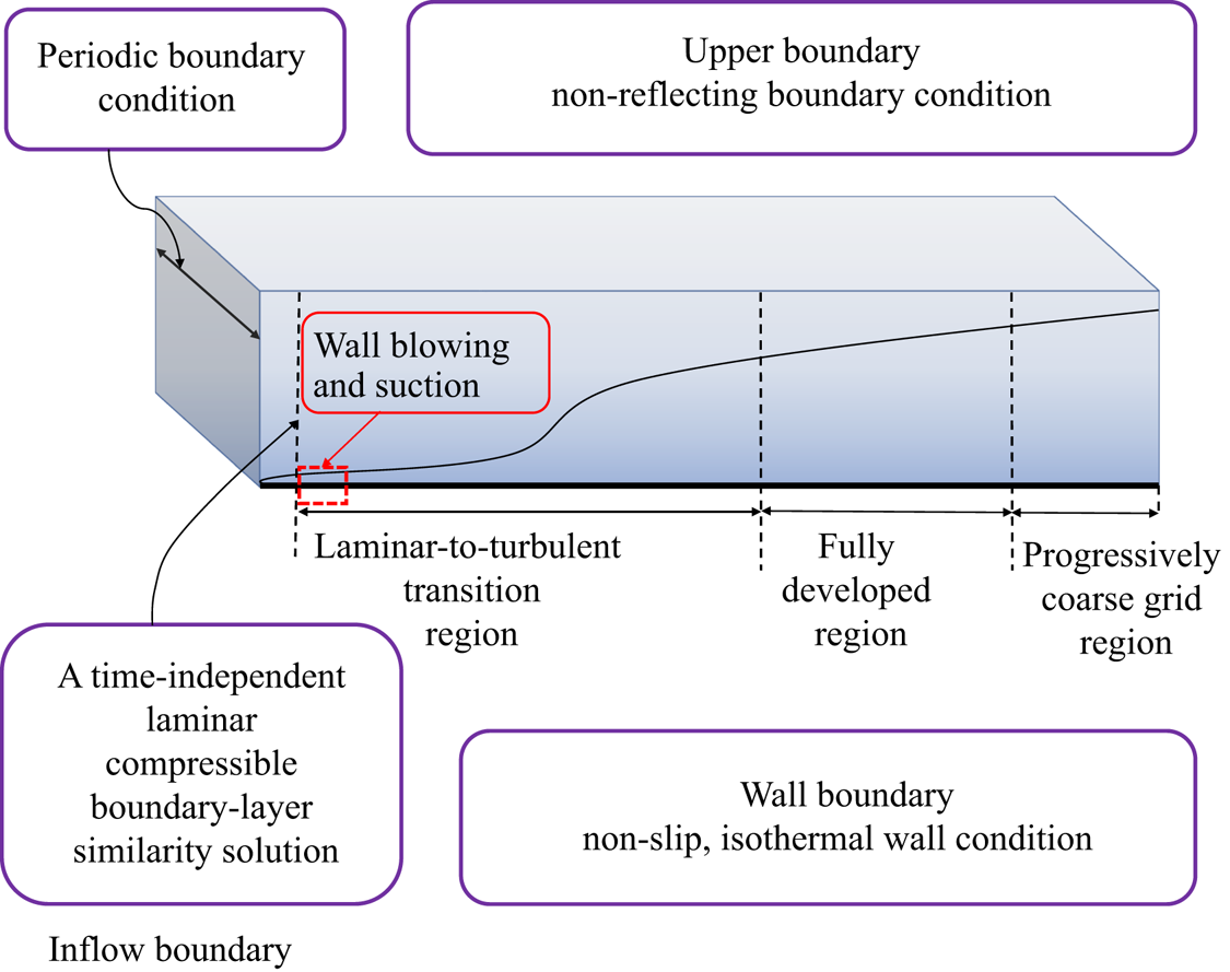
The DNS is performed using the OPENCFD code, which has been widely validated in compressible transitional and turbulent wall-bounded flows (Liang & Li Reference Liang and Li2013, Reference Liang and Li2015; Zhang et al. Reference Zhang, Bi, Hussain and She2014; She et al. Reference She, Zou, Xiao, Chen and Hussain2018; Xu et al. Reference Xu, Wang, Wan, Yu, Li and Chen2021a,Reference Xu, Wang, Wan, Yu, Li and Chenb). A schematic of the hypersonic transitional and turbulent boundary layers is shown in figure 1. The spatially evolving hypersonic transitional and turbulent boundary layers are numerically simulated with the following boundary conditions: the inflow and outflow boundary conditions, a wall boundary condition, an upper far-field boundary condition and a periodic boundary condition in the spanwise direction. To be specific, a time-independent laminar compressible boundary-layer similarity solution is applied at the inflow boundary. A region of wall blowing and suction is implemented to induce the laminar-to-turbulent transition. The blowing and suction disturbance applied on the wall-normal velocity component on the wall can be defined as (Rai, Gatski & Erlebacher Reference Rai, Gatski and Erlebacher1995; Pirozzoli et al. Reference Pirozzoli, Grasso and Gatski2004)
 \begin{equation} v\left ( x,z,t \right )|_{wall}=AU_{\infty }f\left ( x \right )g\left ( z \right )h\left ( t \right ),\quad x_{a}\leq x\leq x_{b}. \end{equation}
Here  $A$ is the amplitude of the disturbance,
 $U_{\infty }$ is the free-stream streamwise velocity and
 $x_{a}=4.5$ and
 $x_{b}=5.0$ are the starting and ending positions of the blowing and suction zone, respectively. Furthermore,
 \begin{gather} f\left ( x \right )=4\sin\theta \left ( 1-\cos\theta \right )/\sqrt{27},\quad\theta =2{\rm \pi} \left ( x-x_{a} \right )/\left ( x_{b}-x_{a} \right ); \end{gather}
 \begin{gather} g\left ( z \right )=\sum_{l=1}^{l_{max}}Z_{l}\sin\left [ 2{\rm \pi} l \left (z/L_{z}+\phi _{l} \right ) \right ],\quad\sum_{l=1}^{l_{max}}Z_{l}=1,\,Z_{l}=1.25Z_{l+1}; \end{gather}
 \begin{gather} h\left ( t \right )=\sum_{m=1}^{m_{max}}T_{m}\sin\left [ 2{\rm \pi} \left (m\beta t+\phi _{m} \right ) \right ],\quad \sum_{m=1}^{m_{max}}T_{m}=1,\,T_{m}=1.25T_{m+1}. \end{gather}
Here  $L_{z}$ is the size of the spanwise domain,
 $l_{max}=10$,
 $m_{max}=5$,
 $\phi _{l}$ and
 $\phi _{m}$ are the phase difference and taken as random numbers ranging between 0 and 1 and
 $\beta \ge 0$ is the base frequency of disturbance.
Schematic of the hypersonic transitional and turbulent boundary layers.

Moreover, in order to inhibit the reflection of disturbance due to the numerical treatment of the outflow boundary condition, a progressively coarse grid is implemented in the streamwise direction near the outflow boundary condition (Pirozzoli et al. Reference Pirozzoli, Grasso and Gatski2004). The non-slip and isothermal boundary conditions are applied for the wall boundary, and the non-reflecting boundary condition is imposed for the upper boundary. Accordingly, the hypersonic transitional and turbulent boundary layer initially undergoes a bypass transition in the laminar-to-turbulent transition region, and then achieves the fully developed state in the fully developed region.
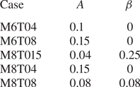
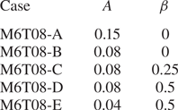
Five hypersonic transitional and turbulent boundary layers at Mach numbers 6 and 8 with different wall temperatures are investigated numerically in the present study. The values of the amplitude of the disturbance  $A$ and the base frequency of disturbance
 $\beta$ of the five hypersonic transitional and turbulent boundary layers are listed in table 1. It is noted that when the base frequency of disturbance
 $\beta =0$, the disturbance is irrelevant to the time
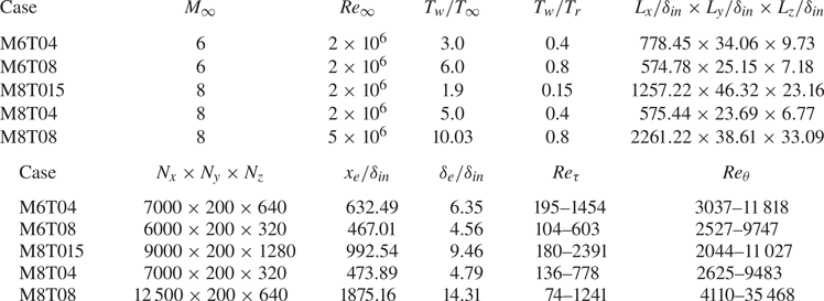
 $t$ and, thus, named as ‘steady disturbance’. The fundamental parameters of the five DNS database are listed in table 2. Here
 $M_{\infty }= U_{\infty }/c_{\infty }$ and
 $Re_{\infty }= \rho _{\infty }U_{\infty }L_{\infty }/\mu _{\infty }$ are the free-stream Mach number and Reynolds number, respectively. The free-stream temperature
 $T_{\infty }$ is assumed to be
 $T_{\infty }=169.44\,{\rm K}$. Temperature
 $T_{w}$ is the wall temperature and the recovery temperature
 $T_{r}$ is defined as
 $T_{r}=T_{\infty } ( 1+r ( ( \gamma -1 )/2 )M_{\infty }^{2} )$ with recovery factor
 $r=0.9$ (Duan et al. Reference Duan, Beekman and Martin2010). Here
 $x$,
 $y$ and
 $z$ are three coordinates along the streamwise, wall-normal and spanwise directions, respectively. The computational domains
 $L_{x}$,
 $L_{y}$ and
 $L_{z}$ are non-dimensionalised by the inflow boundary layer thickness
 $\delta _{in}$. Here
 $N_{x}$,
 $N_{y}$ and
 $N_{z}$ are the grid resolutions along the streamwise, wall-normal and spanwise directions, respectively. The ending streamwise location of the fully developed region shown in figure 1 is represented as
 $x_{e}$ and listed in table 2. The boundary layer thickness at the streamwise location
 $x_{e}$ is defined as
 $\delta _{e}$. We use
 $N$ flow-field snapshots spanning a time interval
 $T_{f}$ for further analysis, where
 $N=2000$ and
 $T_{f}=30x_{e} /U_{\infty }$. The friction Reynolds number
 $Re_{\tau }$ and the Reynolds number
 $Re_{\theta }$ based on the momentum thickness
 $\theta$ are defined as
 $Re_{\tau }=\bar {\rho }_{w}u_{\tau }\delta /\bar {\mu }_{w}$ and
 $Re_{\theta }=\rho _{\infty }u_{\infty }\theta /\bar {\mu }_{w}$, respectively, where
 $\delta$ is the boundary layer thickness and the momentum thickness
 $\theta$ is expressed as
 $\theta =\int _{0}^{\delta }( \bar {\rho }\bar {u} )/( \rho _{\infty }u_{\infty } )( 1-\bar {u}/u_{\infty } )\,{{\rm d} y}$. The ranges of the Reynolds numbers
 $Re_{\tau }$ and
 $Re_{\theta }$ of the five DNS databases are listed in table 2.
Values of  $A$ and
 $\beta$ of the five DNS databases at Mach numbers 6 and 8 with different wall temperatures.

Summary of computational parameters for the five DNS databases at Mach numbers 6 and 8 with different wall temperatures.

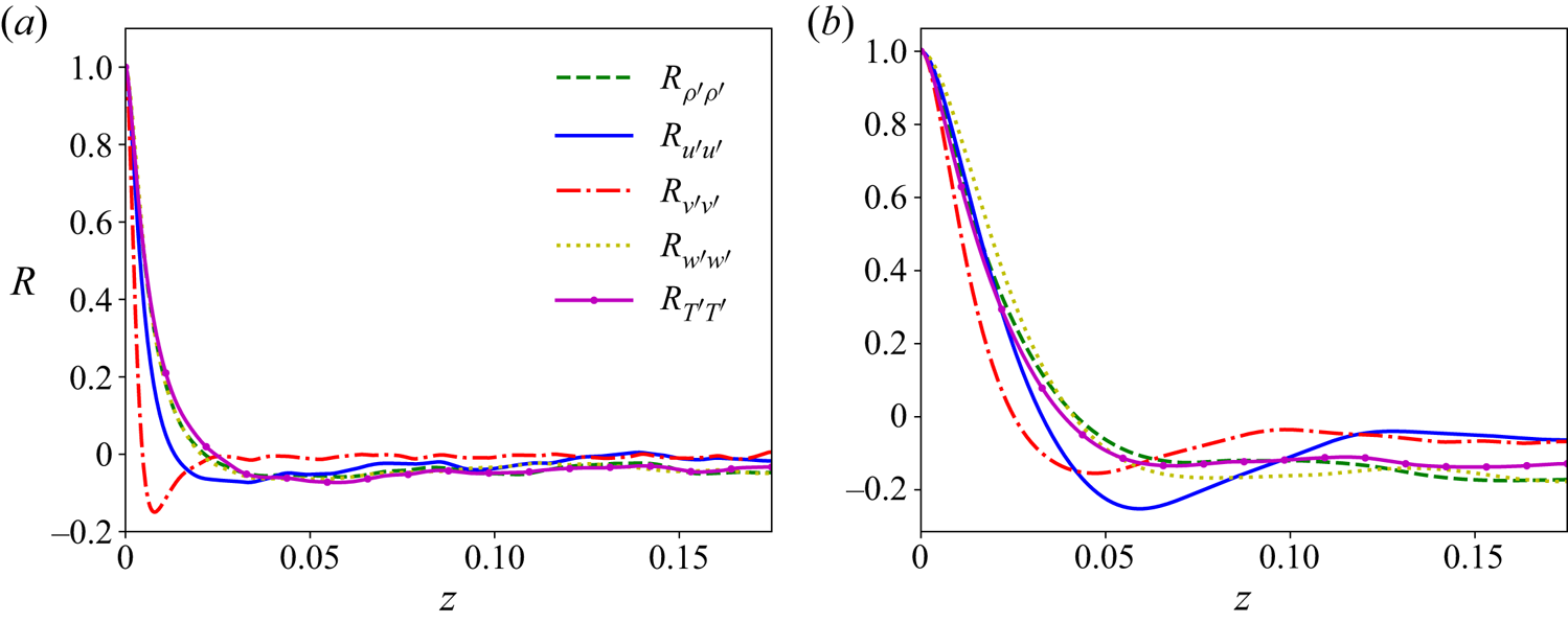
It is noted that the minimum streamwise non-dimensionalised computational domain size of our numerical simulations is comparable to those in most other previous investigations, including Duan et al. (Reference Duan, Beekman and Martin2010), Wenzel et al. (Reference Wenzel, Gibis and Kloker2021a) and Sun et al. (Reference Sun, Guo, Yuan, Zhang, Li and Liu2021). Therefore, the streamwise computational domain sizes are large enough to make the compressible boundary layers evolving to the fully developed state. Furthermore, the adequacy of the computational domain size in the spanwise direction and the grid convergence studies have been confirmed previously in Xu et al. (Reference Xu, Wang, Wan, Yu, Li and Chen2021b). The two-point autocorrelation coefficients at the streamwise location  $x/x_{e}=0.95$ in M8T015 are shown in figure 2. It is shown that the autocorrelations drop to the values close to zero at the centre of the spanwise domain, which indicates that the present spanwise computational domain is sufficiently wide (Pirozzoli et al. Reference Pirozzoli, Grasso and Gatski2004; Duan et al. Reference Duan, Beekman and Martin2010). It is also noted in the following sections that the main results are similar in the five cases of the transitional and turbulent boundary layers. Therefore, the spanwise domain sizes have negligible influence on the results obtained in this study. Moreover, in a previous investigation (Xu et al. Reference Xu, Wang, Wan, Yu, Li and Chen2021b), the mean velocity profiles of these five databases in the fully developed region revealed an obvious log law in the logarithmic layer, and the skin-friction coefficients of the database in the fully developed region showed a good agreement with the theoretical formula for the turbulent skin friction. Many other statistics in the fully developed region of the database, including the Reynolds stress, quadrant analysis and the mean velocity transformations, were shown previously in Xu et al. (Reference Xu, Wang, Wan, Yu, Li and Chen2021a,Reference Xu, Wang, Wan, Yu, Li and Chenb). These investigations indicate that the five hypersonic transitional and turbulent boundary layers have been achieved to the fully developed state.
Two-point autocorrelation coefficients at the streamwise location  $x/x_{e}=0.95$ in M8T015 at (a)
 $y^{+}=100$ and (b)
 $y/\delta =0.8$.

In order to investigate the influence of the values of the amplitude of the disturbance  $A$ and the base frequency of disturbance
 $\beta$ on the flow fields of the hypersonic transitional and turbulent boundary layers, another four additional DNS cases are investigated with the same computational parameters with the case ‘M6T08’ except for the values of
 $A$ and
 $\beta$. The values of
 $A$ and
 $\beta$ of these additional DNS database are listed in table 3. It is noted that the case ‘M6T08-A’ is the same as the case ‘M6T08’. The differences of ‘M6T08-A’ and ‘M6T08-B’ indicates the influence of the amplitude of the disturbance
 $A$ in the steady disturbance, whereas the differences of ‘M6T08-D’ and ‘M6T08-E’ shows the effect of the amplitude of the disturbance
 $A$ with the same
 $\beta$ in the unsteady disturbance. Moreover, the differences of ‘M6T08-B’, ‘M6T08-C’ and ‘M6T08-D’ demonstrate the effect of the base frequency of disturbance
 $\beta$ with the same
 $A$.
Different values of  $A$ and
 $\beta$ of the DNS database with Mach number 6 and
 $T_{w}/T_{r}=0.8$.

The Reynolds analogy factor  $s$ represents the ratio between the wall heat transfer and the wall skin friction, and can be defined as (Zhang et al. Reference Zhang, Bi, Hussain and She2014; Wenzel et al. Reference Wenzel, Gibis, Kloker and Rist2021b)
 \begin{equation} s\equiv \frac{2C_{h}}{C_{f}}=\frac{\overline{q}_{w}u_{\delta }}{\bar{\tau }_{w}C_{p}\left ( T_{w}-T_{r} \right )}. \end{equation}
Here  $C_{f}\equiv \bar {\tau }_{w}/ ( \bar {\rho } _{\delta }\bar {u}_{\delta }^{2}/2 )$ is the skin-friction coefficient, and
 $C_{h}\equiv \overline {q}_{w}/ ( \bar {\rho } _{\delta }\bar {u}_{\delta }C_{p} ( T_{w}-T_{r} ) )$ is the heat-transfer coefficient, i.e. the Stanton number. The subscript
 $\delta$ represents the flow variables evaluated at the boundary-layer edge. Here
 $\bar {\tau }_{w}\equiv (\bar {\mu } \partial \bar {u}/\partial y ) _{y=0}$ is the mean wall shear stress, and
 $\overline {q}_{w}\equiv - ( \overline { ( \kappa /\alpha ) (\partial T/\partial y )} )_{y=0}$ is the wall heat flux. It is noted that the Reynolds analogy factor
 $s$ is the ratio of the heat-transfer coefficient and the skin-friction coefficient. The heat-transfer coefficient and the skin-friction coefficient represent the integral effect of the heat transfer and momentum, respectively, across the boundary layer to the wall based on the decomposition of
 $C_{h}$ and
 $C_{f}$. Accordingly, the Reynolds analogy factor
 $s$ reveals the integral effect of the momentum and heat transfer across the boundary layer at the wall (Wenzel et al. Reference Wenzel, Gibis, Kloker and Rist2021b).
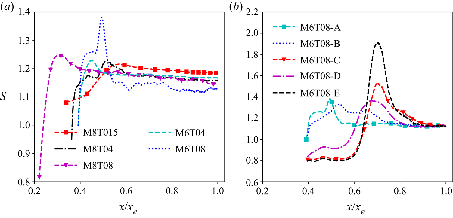
The Reynolds analogy factors  $s$ along the streamwise direction of the five DNS database at Mach numbers 6 and 8 with different wall temperatures are shown in figure 3(a). It should be noted that in this paper, we define ‘the transitional region’ as the region from the position after the wall blowing and suction region to the transition peak. After the transition peak, the skin-friction coefficient, heat-transfer coefficient and the Reynolds analogy factor decreases drastically, and we define this region as the ‘after transition region’. As the streamwise position further increases, the skin-friction coefficient, heat-transfer coefficient and the Reynolds analogy factor begin to evolve slowly, and we define this region as the ‘fully developed region’. These definitions above are consistent with the previous investigations (Liang & Li Reference Liang and Li2013, Reference Liang and Li2015; Zhang et al. Reference Zhang, Bi, Hussain and She2014). It is shown in figure 3(a) that the Reynolds analogy factor
 $s$ is relatively small in the laminar state, mainly because conduction is the primary heat transfer process in this state and has a low heat-transfer efficiency. Then, the laminar flow undergoes the laminar-to-turbulent bypass transition, and the Reynolds analogy factor
 $s$ increases. An overshoot phenomenon is also observed at the transition peak, which is similar to the behaviours of the skin-friction and heat-transfer coefficients in many previous studies (Pirozzoli et al. Reference Pirozzoli, Grasso and Gatski2004; Franko et al. Reference Franko, Bhaskaran and Lele2011; Franko & Lele Reference Franko and Lele2013; Liang & Li Reference Liang and Li2013, Reference Liang and Li2015; Xu et al. Reference Xu, Wang, Wan, Yu, Li and Chen2021b). After the transition peak, the Reynolds analogy factor
 $s$ decreases to the turbulent values, and then remains nearly constant in the fully developed region, indicating that the relatively weak Reynolds-number dependency of
 $s$ in the fully developed region for the moderate Reynolds-number range considered here (Wenzel et al. Reference Wenzel, Gibis, Kloker and Rist2021b). The Reynolds analogy factor
 $s$ of the turbulent flows is much larger than that of the laminar flows, due to the reason that convection becomes the dominant heat transfer process on account of the strong turbulent mixing in turbulent boundary layers, and accordingly has a high heat-transfer efficiency. For compressible turbulent boundary layers, the behaviour of the Reynolds analogy factor
 $s$ is complex and can be relevant to Mach number, wall temperature, surface roughness, pressure gradients and so on. Previous observations indicated that
 $s$ is insensitive to variations of Mach number and wall temperature (Duan et al. Reference Duan, Beekman and Martin2010; Zhang et al. Reference Zhang, Bi, Hussain and She2014; Wenzel et al. Reference Wenzel, Gibis, Kloker and Rist2021b), whereas surface roughness (Peeters & Sandham Reference Peeters and Sandham2019) and pressure gradient (Wenzel et al. Reference Wenzel, Gibis, Kloker and Rist2021b) have strong effects on
 $s$. However, as shown in figure 3(a), the Reynolds analogy factor
 $s$ slightly increases as the wall temperature decreases, especially for the extremely cold wall temperature and very-high-Mach-number case ‘M8T015’, which has the largest values of
 $s$. The reason for the different phenomenon from the previous investigations is probably because the wall temperature is much cooler and the Mach number is much higher than those in previous work, which results in much stronger compressibility. It should be noted that the influence of the wall temperature is much weaker compared with those of the surface roughness and pressure gradient.
(a) Reynolds analogy factor  $s$ along the streamwise direction of the five DNS databases at Mach numbers 6 and 8 with different wall temperatures. (b) Reynolds analogy factor
 $s$ along the streamwise direction of M6T08 with different values of
 $A$ and
 $\beta$.

Moreover, it is worth noting that the adiabatic wall temperature  $T_{r}$ is used to normalise the wall heat flux
 $q_{w}$ for calculating the heat-transfer coefficient
 $C_{h}$. Therefore, the choice of the value of the adiabatic wall temperature
 $T_{r}$ has a strong influence on the value of
 $C_{h}$ and
 $s$. However, the value of adiabatic wall temperature
 $T_{r}$ remains constant at a fixed Mach number with different wall temperatures and, thus, the choice of the adiabatic wall temperature
 $T_{r}$ will not alter the increase tendency of
 $C_{h}$ and
 $s$ as the cooled wall temperature decreases at a fixed Mach number. Furthermore, it is known that the value of adiabatic wall temperature
 $T_{r}$ is different at different Mach numbers and, thus, the choice of the value of the adiabatic wall temperature
 $T_{r}$ has a strong effect if investigating the variation of
 $C_{h}$,
 $s$ and the relevant components along with both the Mach number and wall temperature, i.e. the Eckert number
 $Ec$ in Wenzel et al. (Reference Wenzel, Gibis and Kloker2021a). In order to avoid the influence of the choice of the value of the adiabatic wall temperature
 $T_{r}$ on the conclusions obtained in this paper, only the variations along with the cooled wall temperature at the fixed Mach number are discussed, and the variations along with the cooled wall temperature are applicable in the Mach number range investigated in this paper.
The Reynolds analogy factors  $s$ along the streamwise direction of M6T08 with different values of
 $A$ and
 $\beta$ are shown in figure 3(b) to investigate the effect of different wall blowing and suction parameters on the evolution of the hypersonic transitional and turbulent boundary layers. It is shown that the different values of
 $A$ and
 $\beta$ only have a significant influence on the transitional region of the boundary layers. However, for the fully developed region, all five DNS cases of M6T08 converge to the same values of
 $s$, indicating that the values of
 $A$ and
 $\beta$ have a negligible influence on the turbulent boundary layers. Moreover, it is shown that the streamwise locations of the transition peak of M6T08-A and M6T08-B are smaller than those of the other three cases, which indicates that the steady disturbance will bring the transition forward compared with the unsteady disturbance. The streamwise locations of the transition peak of M6T08-A and M6T08-D are smaller than those of M6T08-B and M6T08-E respectively, demonstrating that the smaller amplitude of the disturbance
 $A$ will delay the transition. It is also shown that the overshoot phenomena of the Reynolds analogy factor
 $s$ exist in all five cases of M6T08.
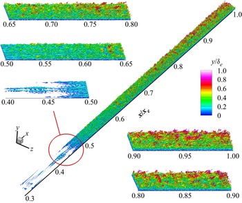
The visualisation of the instantaneous vortical structures based on the  $Q$-criterion (Hunt, Wray & Moin Reference Hunt, Wray and Moin1988) of the hypersonic transitional and turbulent boundary layer in M8T015 is shown in figure 4. The structures are coloured by the wall-normal location
 $y/\delta _{e}$. This picture depicts the streamwise evolution of the instantaneous vortical structures in the whole laminar-to-turbulent transition process. It is shown that at the onset of the flat plate, the laminar flow is disturbed by the wall blowing and suction, and then results in the streamwise vorticity near the wall (appears at the streamwise position
 $x/x_{e}=0.4-0.45$ in figure 4). Furthermore, the high- and low-momentum streaks are generated by the lift-up effect (Franko & Lele Reference Franko and Lele2013), and more and more vortical structures appear far from the wall as the boundary layer evolves. It can be seen that the vortical structures far from the wall are blob-like structures, while those near the wall are sheet-like structures, mainly due to the strong mean shear in the near-wall region.
Visualisation of the instantaneous vortical structures based on the Q-criterion (Hunt et al. Reference Hunt, Wray and Moin1988) of the hypersonic transitional and turbulent boundary layer in M8T015. The structures are coloured by the wall-normal location  $y/\delta _{e}$. The isosurfaces of the instantaneous vortical structures represent
 $Q=10$.

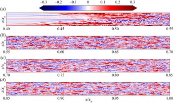
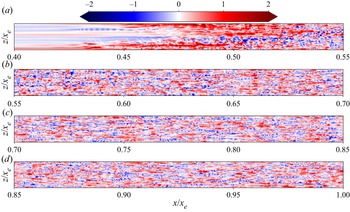
Furthermore, instantaneous fields of  ${u}''$ and
 ${T}''$ in a wall-parallel plane at
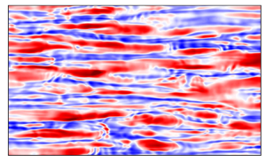
 $y/\delta _{in}=0.035$ in M8T015 are plotted in figures 5 and 6, respectively. It is seen that the structures of
 ${u}''$ and
 ${T}''$ are similar to each other, which is consistent with the observation in Xu et al. (Reference Xu, Wang, Wan, Yu, Li and Chen2021a) that the correlation values between
 ${u}''$ and
 ${T}''$ are almost equal to 1 in the near-wall region. At the onset of the bypass transition process (at the streamwise position
 $x/x_{e}=0.4-0.45$), the streak instability shows to be a sinuous structure, which is consistent with the behaviours in compressible (Franko & Lele Reference Franko and Lele2013) and incompressible (Andersson et al. Reference Andersson, Brandt, Bottaro and Henningson2001) flows. The sinuous disturbances lead to the high- and low-momentum and temperature streaks, and these streaks then break down to a fully turbulent flows (Franko & Lele Reference Franko and Lele2013).
Instantaneous field of  ${u}''$ in a wall-parallel plane at
 $y/\delta _{in}=0.035$ in M8T015. It is noted that the wall-normal location
 $y/\delta _{in}=0.035$ is consistent with
 $y^{+}=10$ at the streamwise location
 $x/x_{e}=0.95$.

Instantaneous field of  ${T}''$ in a wall-parallel plane at
 $y/\delta _{in}=0.035$ in M8T015. It is noted that the wall-normal location
 $y/\delta _{in}=0.035$ is consistent with
 $y^{+}=10$ at the streamwise location
 $x/x_{e}=0.95$.

3. Decompositions of the skin-friction and heat-transfer coefficients
Integral identities are helpful to investigate the wall skin friction and heat transfer by the contributions from the flow statistics inside the flow domain, which can help to figure out the generation mechanisms of wall skin friction and heat transfer and design flow-control strategies. The integral analysis has been used widely in previous investigations by integrating different types of conservation laws, including mean momentum (Fukagata et al. Reference Fukagata, Iwamoto and Kasagi2002; Xia et al. Reference Xia, Zhang and Yang2021; Wenzel et al. Reference Wenzel, Gibis and Kloker2021a), mean kinetic energy (Renard & Deck Reference Renard and Deck2016), mean energy (Arntz, Atinault & Merlen Reference Arntz, Atinault and Merlen2015), mean total enthalpy (Wenzel et al. Reference Wenzel, Gibis and Kloker2021a) and mean internal energy (Zhang & Xia Reference Zhang and Xia2020). In this study, the integral identities of the mean momentum and internal energy are analysed to investigate the contributions of internal flow statistics to the skin-friction coefficient  $C_{f}$ as well as the heat-transfer coefficient
 $C_{h}$.
The two-dimensional boundary-layer equations for the mean streamwise momentum and mean temperature can be written as
 \begin{align} &-\bar{\rho }\tilde{u}\frac{\partial \tilde{u}}{\partial x}-\bar{\rho }\tilde{v}\frac{\partial \tilde{u}}{\partial y}-\frac{\partial \bar{p}}{\partial x}+\frac{1}{Re}\left ( \frac{\partial \bar{\sigma}_{xx} }{\partial x} + \frac{\partial \bar{\sigma}_{xy} }{\partial y}\right )\nonumber\\ &\qquad-\frac{\partial \left (\bar{\rho }\widetilde{{u}''{u}''} \right )}{\partial x}-\frac{\partial \left (\bar{\rho }\widetilde{{u}''{v}''}\right )}{\partial y}=0, \end{align}
 \begin{align} &-\bar{\rho }\tilde{u}\frac{\partial \tilde{T}}{\partial x}-\bar{\rho }\tilde{v}\frac{\partial \tilde{T}}{\partial y}-\overline{\rho \left ( \gamma -1 \right )T\frac{\partial u_{j}}{\partial x_{j}}}+\overline{\frac{\sigma _{ij}}{C_{v}Re}\frac{\partial u_{i}}{\partial x_{j}}}+\overline{\frac{1}{C_{v}\alpha }\frac{\partial }{\partial x}\left ( \kappa \frac{\partial T}{\partial x} \right )}\nonumber\\ &\qquad +\overline{\frac{1}{C_{v}\alpha }\frac{\partial }{\partial y}\left ( \kappa \frac{\partial T}{\partial y} \right )}-\frac{\partial \left (\bar{\rho }\widetilde{{T}''{u}''} \right )}{\partial x}-\frac{\partial \left (\bar{\rho }\widetilde{{T}''{v}''}\right )}{\partial y}=0. \end{align}
The formulae of the  $n$ repeated integrations of the skin-friction and heat-transfer coefficients are derived in Appendix B. It is noted that similar to Wenzel et al. (Reference Wenzel, Gibis and Kloker2021a), the formula of the
 $n$ repeated integration of the skin-friction coefficient
 $C_{f}$ is based on the mean momentum equation. However, when it comes to the heat-transfer coefficient
 $C_{h}$, the derivation method is different from that in Wenzel et al. (Reference Wenzel, Gibis and Kloker2021a). In Wenzel et al. (Reference Wenzel, Gibis and Kloker2021a), the decomposition formula of
 $C_{h}$ is based on the mean total enthalpy, whereas the decomposition of
 $C_{h}$ is based on the mean internal energy in this study. In our opinion, the decomposition based on the mean internal energy is more straightforward and concise to investigate the heat transfer between the whole boundary layer and the wall. Furthermore, a decomposed term related to the Reynolds heat flux
 $\rho {v}''{T}''$ can be only found in the decomposition based on the mean internal energy, which is significant to investigate the role of the Reynolds heat flux on the overshoot phenomenon of
 $C_{h}$.
It should be noted that an arbitrary value of  $n$
 $( n>1 )$ can lead to a valid decomposition of
 $C_{f}$ and
 $C_{h}$; however, not all values of
 $n$ can result in a physically plausible interpretation (Wenzel et al. Reference Wenzel, Gibis and Kloker2021a). The well-known FIK identity (Fukagata et al. Reference Fukagata, Iwamoto and Kasagi2002) is based on a threefold
 $( n=3 )$ integration of the streamwise momentum equation, but a drawback of the FIK identity is the lack of a physical-based interpretation of some contributing terms (Renard & Deck Reference Renard and Deck2016; Li et al. Reference Li, Fan, Modesti and Cheng2019; Wenzel et al. Reference Wenzel, Gibis and Kloker2021a). As suggested by Ghosh, Foysi & Friedrich (Reference Ghosh, Foysi and Friedrich2010), Zhang & Xia (Reference Zhang and Xia2020) and Wenzel et al. (Reference Wenzel, Gibis and Kloker2021a), a twofold
 $( n=2 )$ repeated integration is a more physically sound choice. This can be explained as follows. The first integration leads to a force and energy balance between the wall and other wall-normal locations within the boundary layer, and the second integration leads to an average in the wall-normal direction (Zhang & Xia Reference Zhang and Xia2020; Wenzel et al. Reference Wenzel, Gibis and Kloker2021a).
Furthermore, it is well known that the Reynolds shear stress  $\bar {\rho }\widetilde {{u}''{v}''}$ and the Reynolds heat flux
 $\bar {\rho }\widetilde {{T}''{v}''}$ represent the turbulent convection of momentum and internal energy, respectively, and these two terms were considered as the reasons of the overshoot phenomena of the mean skin-friction and heat-transfer coefficients at the transition peak in Franko & Lele (Reference Franko and Lele2013). In the threefold FIK decomposition, a weight function
 $( y_{b}-y )$ appears before
 $\bar {\rho }\widetilde {{u}''{v}''}$ and
 $\bar {\rho }\widetilde {{T}''{v}''}$ as shown in Wenzel et al. (Reference Wenzel, Gibis and Kloker2021a). In the RD decomposition, another weight function
 $\partial \tilde {u}/ \partial y$ exists before
 $\bar {\rho }\widetilde {{u}''{v}''}$ and
 $\bar {\rho }\widetilde {{T}''{v}''}$ as shown in Li et al. (Reference Li, Fan, Modesti and Cheng2019) and Zhang et al. (Reference Zhang, Song and Xia2022). These additional weight functions results in different weighting at different wall-normal locations, and are lacking physical interpretation. However, in the twofold FIK decomposition, no extra weight function exists before
 $\bar {\rho }\widetilde {{u}''{v}''}$ and
 $\bar {\rho }\widetilde {{T}''{v}''}$. The components including
 $\bar {\rho }\widetilde {{u}''{v}''}$ and
 $\bar {\rho }\widetilde {{T}''{v}''}$ in the twofold FIK decomposition represent the wall-normal average of the turbulent convection of momentum and internal energy, respectively, and accordingly are the contributions of turbulent convection from the whole boundary layer to the wall skin friction and heat flux. Therefore, through analysing the contributions of
 $\bar {\rho }\widetilde {{u}''{v}''}$ and
 $\bar {\rho }\widetilde {{T}''{v}''}$ from the whole boundary layer to the wall skin friction and heat flux, conclusions can be obtained that whether the Reynolds shear stress and the Reynolds heat flux are the major reasons of the overshoot phenomena of the mean skin-friction and heat-transfer coefficients, respectively, at the transition peak as Franko & Lele (Reference Franko and Lele2013) claimed. To sum up, in our opinion, the twofold FIK decomposition is a better method with more clear physical interpretation, and will be used in this paper.
Accordingly, if  $n=2$, equations (B 2) and (B 3) can be simplified as
 \begin{equation} C_{f}=C^{B}_{f}+C^{V}_{f}+C^{T}_{f}+C^{M}_{f}+C^{D,1}_{f}+C^{D,2}_{f}+C^{D,3}_{f}+C^{D,4}_{f}, \end{equation}
 \begin{equation} C_{h}=C^{B}_{h}+C^{T}_{h}+C^{V}_{h}+C^{M}_{h}+C^{P}_{h}+C^{D,1}_{h}+C^{D,2}_{h}+C^{D,3}_{h}, \end{equation}
where
 \begin{gather} C_{f}^{B}\equiv \frac{2}{\bar{\rho} _{\delta }\bar{u}_{\delta }^{2}y_{b}}\int_{0}^{y_{b}}\left [ \frac{1}{Re}\left ( \bar{\mu }\frac{\partial \bar{u}}{\partial y}+\bar{\mu }\frac{\partial \bar{v}}{\partial x} \right ) \right ]\,{{\rm d} y}, \end{gather}
 \begin{gather} C_{f}^{V}\equiv \frac{2}{\bar{\rho} _{\delta }\bar{u}_{\delta }^{2}y_{b}}\int_{0}^{y_{b}}\left [ \overline{{\mu }'\left ( \frac{\partial {u}'}{\partial y}+\frac{\partial {v}'}{\partial x} \right )} \right ]\,{{\rm d} y}, \end{gather}
 \begin{gather} C_{f}^{T}\equiv{-}\frac{2}{\bar{\rho} _{\delta }\bar{u}_{\delta }^{2}y_{b}}\int_{0}^{y_{b}}\bar{\rho }\widetilde{{u}''{v}''}\,{{\rm d} y}, \end{gather}
 \begin{gather} C_{f}^{M}\equiv{-}\frac{2}{\bar{\rho} _{\delta }\bar{u}_{\delta }^{2}y_{b}}\int_{0}^{y_{b}}\left ( y_{b}-y \right )\bar{\rho }\tilde{v}\frac{\partial \tilde{u}}{\partial y}\,{{\rm d} y}, \end{gather}
 \begin{gather} C_{f}^{D,1}\equiv{-}\frac{2}{\bar{\rho} _{\delta }\bar{u}_{\delta }^{2}y_{b}}\int_{0}^{y_{b}}\left ( y_{b}-y \right ) \bar{\rho }\tilde{u}\frac{\partial \tilde{u}}{\partial x}\,{{\rm d} y}, \end{gather}
 \begin{gather} C_{f}^{D,2}\equiv{-}\frac{2}{\bar{\rho} _{\delta }\bar{u}_{\delta }^{2}y_{b}}\int_{0}^{y_{b}}\left ( y_{b}-y \right ) \frac{\partial \bar{p}}{\partial x}\,{{\rm d} y}, \end{gather}
 \begin{gather} C_{f}^{D,3}\equiv \frac{2}{\bar{\rho} _{\delta }\bar{u}_{\delta }^{2}y_{b}}\int_{0}^{y_{b}}\left ( y_{b}-y \right ) \frac{1}{Re}\frac{\partial \bar{\sigma}_{xx} }{\partial x}\,{{\rm d} y}, \end{gather}
 \begin{gather} C_{f}^{D,4}\equiv{-}\frac{2}{\bar{\rho} _{\delta }\bar{u}_{\delta }^{2}y_{b}}\int_{0}^{y_{b}}\left ( y_{b}-y \right )\frac{\partial \left (\bar{\rho }\widetilde{{u}''{u}''} \right )}{\partial x}\,{{\rm d} y}; \end{gather}
and
 \begin{gather} C^{B}_{h}\equiv \frac{C_{v}}{\left ( \bar{\rho} _{\delta }\bar{u}_{\delta }C_{p}\left ( T_{r}-T_{w} \right ) \right )y_{b}}\int_{0}^{y_{b}}\overline{\frac{1}{C_{v}\alpha }\left ( \kappa \frac{\partial T}{\partial y} \right )}\,{{\rm d} y}, \end{gather}
 \begin{gather} C^{T}_{h}\equiv{-}\frac{C_{v}}{\left ( \bar{\rho} _{\delta }\bar{u}_{\delta }C_{p}\left ( T_{r}-T_{w} \right ) \right )y_{b}}\int_{0}^{y_{b}}\bar{\rho }\widetilde{{T}''{v}''}\,{{\rm d} y}, \end{gather}
 \begin{gather} C^{V}_{h}\equiv \frac{C_{v}}{\left ( \bar{\rho} _{\delta }\bar{u}_{\delta }C_{p}\left ( T_{r}-T_{w} \right ) \right )y_{b}}\int_{0}^{y_{b}}\left ( y_{b}-y \right )\overline{\frac{\sigma _{ij}}{C_{v}Re}\frac{\partial u_{i}}{\partial x_{j}}} \,{{\rm d} y}, \end{gather}
 \begin{gather} C^{M}_{h}\equiv{-}\frac{C_{v}}{\left ( \bar{\rho} _{\delta }\bar{u}_{\delta }C_{p}\left ( T_{r}-T_{w} \right ) \right )y_{b}}\int_{0}^{y_{b}}\left ( y_{b}-y \right )\bar{\rho }\tilde{v}\frac{\partial \tilde{T}}{\partial y} \,{{\rm d} y}, \end{gather}
 \begin{gather} C^{P}_{h}\equiv{-}\frac{C_{v}}{\left ( \bar{\rho} _{\delta }\bar{u}_{\delta }C_{p}\left ( T_{r}-T_{w} \right ) \right )y_{b}}\int_{0}^{y_{b}}\left ( y_{b}-y \right )\overline{\rho \left ( \gamma -1 \right )T\frac{\partial u_{j}}{\partial x_{j}}} \,{{\rm d} y}, \end{gather}
 \begin{gather} C^{D,1}_{h}\equiv{-}\frac{C_{v}}{\left ( \bar{\rho} _{\delta }\bar{u}_{\delta }C_{p}\left ( T_{r}-T_{w} \right ) \right )y_{b}}\int_{0}^{y_{b}}\left ( y_{b}-y \right )\bar{\rho }\tilde{u}\frac{\partial \tilde{T}}{\partial x}\,{{\rm d} y}, \end{gather}
 \begin{gather} C^{D,2}_{h}\equiv{-}\frac{C_{v}}{\left ( \bar{\rho} _{\delta }\bar{u}_{\delta }C_{p}\left ( T_{r}-T_{w} \right ) \right )y_{b}}\int_{0}^{y_{b}}\left ( y_{b}-y \right )\frac{\partial \left (\bar{\rho }\widetilde{{T}''{u}''} \right )}{\partial x}\,{{\rm d} y}, \end{gather}
 \begin{gather} C^{D,3}_{h}\equiv \frac{C_{v}}{\left ( \bar{\rho} _{\delta }\bar{u}_{\delta }C_{p}\left ( T_{r}-T_{w} \right ) \right )y_{b}}\int_{0}^{y_{b}}\left ( y_{b}-y \right )\overline{\frac{1}{C_{v}\alpha }\frac{\partial }{\partial x}\left ( \kappa \frac{\partial T}{\partial x} \right )}\,{{\rm d}y}. \end{gather}
Here  $C_{f}^{B}$ is the mean boundary-layer term;
 $C_{f}^{V}$ is the viscous boundary-layer term;
 $C_{f}^{T}$ is the turbulent-convection term;
 $C_{f}^{M}$ is the vertical mean-convection term;
 $C_{f}^{D,1}$ is the streamwise mean-convection term;
 $C_{f}^{D,2}$,
 $C_{f}^{D,3}$ and
 $C_{f}^{D,4}$ are the spatial-development terms;
 $C^{B}_{h}$ is the mean boundary-layer term;
 $C^{T}_{h}$ is the turbulent-convection term;
 $C^{V}_{h}$ is the viscous-dissipation term;
 $C^{M}_{h}$ is the vertical mean-convection term;
 $C^{P}_{h}$ is the pressure-dilatation term;
 $C^{D,1}_{h}$ is the streamwise mean-convection term;
 $C^{D,2}_{h}$ and
 $C^{D,3}_{h}$ are the spatial-development terms.
The value of the upper integration limit  $y_{b}$ drastically influences the relative contributions of different terms. As confirmed in Wenzel et al. (Reference Wenzel, Gibis and Kloker2021a), the particular value of
 $y_{b}$ has a weak effect on the qualitative contributions of different components if
 $y_{b}$ approximates to the boundary-layer thickness
 $\delta$. Moreover, it has also been confirmed in our DNS database that the choice of the value of
 $y_{b}$ has a negligible influence on the qualitative conclusions if
 $y_{b}>\delta$, and the relevant results are omitted for brevity. Thus, in the present study, we set the upper integration limit as
 $y_{b}\approx 1.5\delta _{e}$ to cover the thermal boundary layer, and the upper integration limit is assumed to be constant along the streamwise direction.
Before the detailed descriptions of the trends of different components in (3.3) and (3.4) along the streamwise direction, some physical interpretations are given for better understanding the effect of these components on the skin-friction and heat-transfer coefficients. The positive value of a component means that this component enhances the skin-friction and heat-transfer coefficients, and contributes the force and internal energy from the whole boundary layer to the wall skin friction and heat flux, respectively, in the integral sense. In contrast, the negative value of a component means that this component reduces the skin-friction and heat-transfer coefficients, and carries the extra force and internal energy from the wall skin friction and heat flux to the boundary layer, respectively, in the integral sense (Sun et al. Reference Sun, Guo, Yuan, Zhang, Li and Liu2021). Moreover, the increasing nature of a positive component along the streamwise direction means that this component contributes much more force and internal energy from the whole boundary layer to the wall skin friction and heat flux, respectively, whereas the enhancing nature of the magnitude of a negative component along the streamwise direction indicates that this component can reduce the skin-friction and heat-transfer coefficients more significantly with the increase of the streamwise location.
4. Streamwise evolution of  $C_{f}$

It is noted that the streamwise location  $x$ is non-dimensionalised by
 $x_{e}$ rather than
 $\delta _{in}$ in the following discussion, mainly due to the reason as follows: it is seen in table 2 that the ranges of
 $L_{x}/\delta _{in}$ are totally different for the five DNS databases. If the streamwise evolutions of some flow statistics of the five DNS databases are compared in the same figure, the ranges of the
 $x$-axes are different in the five databases, thus it is difficult to compare the streamwise evolutions of the five databases. If the streamwise location
 $x$ is non-dimensionalised by
 $x_{e}$, the ranges of the
 $x$-axes in the five databases are almost the same, which makes it much easier to compare between different cases.
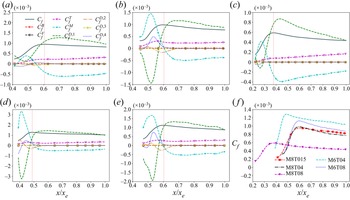
The streamwise evolutions of the skin-friction coefficient  $C_{f}$ and its components in (3.3) in the hypersonic transitional and turbulent boundary layers are shown in figure 7. It is shown that the skin-friction coefficient
 $C_{f}$ initially increases due to the bypass transition process, then achieves to a peak value at the transition peak, and finally slightly decreases as the streamwise location
 $x/x_{e}$ increases. An interesting phenomenon is shown that the peak value of the skin-friction coefficient
 $C_{f}$ overshoots the turbulent values in the nonlinear breakdown regime before ultimately decreasing towards the turbulent boundary layer values, which has been widely observed in previous investigations (Brandt & Henningson Reference Brandt and Henningson2002; Horvath et al. Reference Horvath, Berry and Hollis2002; Pirozzoli et al. Reference Pirozzoli, Grasso and Gatski2004; Franko et al. Reference Franko, Bhaskaran and Lele2011; Franko & Lele Reference Franko and Lele2013; Liang & Li Reference Liang and Li2013, Reference Liang and Li2015). Moreover, the values of
 $C_{f}$ in the fully developed region increase as the wall temperature decreases.
Streamwise evolutions of the skin-friction coefficient  $C_{f}$ and its components in (3.3) in the hypersonic transitional and turbulent boundary layers in (a) M8T015, (b) M8T04, (c) M8T08, (d) M6T04 and (e) M6T08. (f) The streamwise evolutions of the skin-friction coefficient
 $C_{f}$ in five hypersonic transitional and turbulent boundary layers. The vertical dashed line represents the streamwise position of the transition peak.

The trends of the contributions of the skin-friction coefficient  $C_{f}$ along the streamwise direction are similar in different hypersonic transitional and turbulent boundary layers. It is shown that the vertical mean-convection term
 $C_{f}^{M}$ initially increases at the onset of the bypass transition process and gives the positive contribution to
 $C_{f}$, and then begins to decrease at the centre of the bypass transition process. After the transition peak,
 $C_{f}^{M}$ decreases to negative values and accordingly gives a negative contribution to
 $C_{f}$. The magnitudes of
 $C_{f}^{M}$ slightly decrease as the streamwise position increases to the region of the fully developed state. The streamwise mean-convection term
 $C_{f}^{D,1}$ has the opposite trends along the streamwise direction compared with
 $C_{f}^{M}$. The terms
 $C_{f}^{M}$ and
 $C_{f}^{D,1}$ give the dominant contributions to
 $C_{f}$, and represent the influence of the mean convection on the skin-friction coefficient. The turbulent-convection term
 $C_{f}^{T}$ increases along the streamwise direction and gives the positive contribution to
 $C_{f}$, due to the reason that the Reynolds shear stress is enhanced by the bypass transition process. The spatial-development terms
 $C_{f}^{D,2}$ and
 $C_{f}^{D,4}$ represent the effect of the streamwise pressure gradient and streamwise normal Reynolds stress gradient, respectively. The term
 $C_{f}^{D,2}$ shows that the streamwise pressure gradient leads to the positive contribution at the onset of the bypass transition process, and then changes to the negative contribution to
 $C_{f}$ before the transition peak. After the transition peak, the term
 $C_{f}^{D,2}$ is almost zero due to the zero-pressure-gradient boundary layer setting. The term
 $C_{f}^{D,4}$ indicates that the streamwise normal Reynolds stress gradient results in the negative contribution at the initial state of the bypass transition process, and then switches to the positive contribution to
 $C_{f}$ before the transition peak. The term
 $C_{f}^{D,4}$ has negligible values after the transition peak. Other components in (3.3) are negligible in the transitional and turbulent boundary layers.
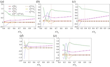
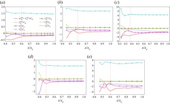
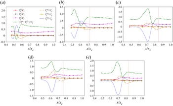
The streamwise evolutions of the relative contributions of the components in (3.3) to the skin-friction coefficient  $C_{f}$ in the hypersonic transitional and turbulent boundary layers are plotted in figure 8. It is noted that
 $C_{f}^{M}$ represents the vertical mean convection effect and
 $C_{f}^{D,1}$ represents the streamwise mean convection effect. If
 $C_{f}^{M}$ and
 $C_{f}^{D,1}$ are summed up, the term
 $C_{f}^{M}+C_{f}^{D,1}$ represents the mean convection effect both in the vertical and streamwise directions. It is shown that the terms
 $C_{f}^{M}+C_{f}^{D,1}$,
 $C_{f}^{T}$,
 $C_{f}^{D,2}$ and
 $C_{f}^{D,4}$ are dominant in
 $C_{f}$ in the bypass transition process, indicating that the mean convection, the Reynolds shear stress, the streamwise pressure gradient and the streamwise normal Reynolds stress gradient are significant mechanisms during the bypass transition process in the integral sense. In the bypass transition process, the time-independent laminar compressible boundary-layer flow is disturbed by the wall blowing and suction, which results in the generation of high- and low-momentum streaks by the lift-up effect (Franko & Lele Reference Franko and Lele2013). Then the streaks breakdown locally and evolve into the turbulent spots. Among the whole process, the mean velocity profiles are significantly changed by the large-amplitude fluctuations of the instability waves and result in large mean velocity gradients. Then, the breakdown of the high- and low-momentum streaks leads to the increase of the Reynolds shear stress and strong streamwise normal Reynolds stress gradient along streamwise direction in the transition region.
Streamwise evolutions of the relative contributions of the components in (3.3) to the skin-friction coefficient  $C_{f}$ in the hypersonic transitional and turbulent boundary layers in (a) M8T015, (b) M8T04, (c) M8T08, (d) M6T04 and (e) M6T08. The vertical dashed line represents the streamwise position of the transition peak.

It is shown that at the transition peak, the term  $C_{f}^{M}+C_{f}^{D,1}$ gives the dominant positive contribution, and the term
 $C_{f}^{T}$ also gives a large positive contribution to the skin-friction coefficient
 $C_{f}$. Moreover, the terms
 $C_{f}^{D,2}$ and
 $C_{f}^{D,4}$ have relatively small negative and positive contributions to
 $C_{f}$, respectively. It is noted that the value of
 $(C_{f}^{M}+C_{f}^{D,1} )/C_{f}$ at the transition peak is larger than that in the fully developed state, whereas that of
 $C_{f}^{T}/C_{f}$ at the transition peak is smaller than that in the fully developed state. Therefore, the Reynolds shear stress at the transition peak is not a dominant mechanism of the overshoot phenomenon, which is different from the conclusion by Franko & Lele (Reference Franko and Lele2013); instead, the overshoot of
 $C_{f}$ is mainly caused by the drastic change of the mean velocity profiles in the integral sense.
However, when the flow evolves to the fully developed state, only the terms  $C_{f}^{M}+C_{f}^{D,1}$ and
 $C_{f}^{T}$ are positive, whereas other terms are negligibly small. It is shown that the term
 $C_{f}^{M}+C_{f}^{D,1}$ has the dominant contribution to
 $C_{f}$, which is consistent with the observation in subsonic and supersonic turbulent boundary layers (Wenzel et al. Reference Wenzel, Gibis and Kloker2021a). The relative contribution of
 $C_{f}^{M}+C_{f}^{D,1}$ to
 $C_{f}$ slightly decreases, whereas that of
 $C_{f}^{T}$ mildly increases as the streamwise position increases until to the fully developed region.
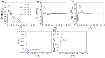
The pre-multiplied integrands of the relative contributions of  $C_{f}^{T}$ to the skin-friction coefficient
 $C_{f}$ at different streamwise positions in M8T015 are shown in figure 9(a). The label ‘
 $x_{t}$’ represents the streamwise position of the transition peak. It is seen that the peak value of the pre-multiplied integrand of the relative contributions of
 $C_{f}^{T}$ is large at the middle of the transition region. Moreover, the peak value becomes smaller and the wall-normal location of the peak value becomes nearer to the wall as the streamwise position
 $x/x_{e}$ increases. As the boundary layers evolve into the fully developed state, the peak value and the wall-normal location of the peak value are almost the same at different streamwise locations. The peak values of the pre-multiplied integrands of the relative contributions of
 $C_{f}^{T}$ in the transition region are much larger than those in the fully developed region, which is consistent with the fact observed in Franko & Lele (Reference Franko and Lele2013) that a peak value of the normalised Reynolds shear stress
 $2\bar {\rho }\widetilde {{u}''{v}''}/(\bar {\rho } _{\delta }\bar {u}_{\delta }^{2}C_{f})$ appears at the transition peak. These statistical observations are consistent with the instantaneous field of
 ${u}''$ shown in figure 5. It is shown in figure 5 that the structures of
 ${u}''$ are much thicker in the transition region than those in the fully developed region, and the magnitudes of the fluctuation
 ${u}''$ are much larger in the transition region than those in the fully developed region, leading to the much larger peak values of the normalised Reynolds shear stress in the transition region. However, the areas under the curves of the pre-multiplied integrands of the relative contributions of
 $C_{f}^{T}$ with the linear-scaling
 $x$-axis represent the contributions of
 $C_{f}^{T}$ to the skin-friction coefficient
 $C_{f}$, and the areas in the transition region are much smaller than those in the fully developed region, indicating that the relative contributions of
 $C_{f}^{T}$ to the skin-friction coefficient
 $C_{f}$ in the transition region are smaller than those in the fully developed region. Accordingly, the large peak values of the normalised Reynolds shear stress at the transition peak is not the appropriate reason of the overshoot phenomenon of the skin-friction coefficient
 $C_{f}$.
Pre-multiplied integrands of the relative contributions of (a)  $C_{f}^{T}$, (b)
 $C_{f}^{M}$, (c)
 $C_{f}^{D,1}$ and (e)
 $C_{f}^{M}+C_{f}^{D,1}$ to the skin-friction coefficient
 $C_{f}$ at different streamwise positions in M8T015. (d) Streamwise gradient of the mean streamwise velocity
 $\partial \tilde {u}/\partial x$ in M8T015. Here the abbreviation ‘PI’ represents the pre-multiplied integrand, and ‘
 $x_{t}$’ represents the streamwise position of the transition peak. The pre-multiplied integrand of
 $C_{f}^{T}/C_{f}$ is defined as
 $-({2\bar {\rho }\widetilde {{u}''{v}''}}/{\bar {\rho } _{\delta }\bar {u}_{\delta }^{2}C_{f}})$; the pre-multiplied integrand of
 $C_{f}^{M}/C_{f}$ is defined as
 $-({2}/{\bar {\rho } _{\delta }\bar {u}_{\delta }^{2}C_{f}}) ( y_{b}-y ) (\bar {\rho }\tilde {v}({\partial \tilde {u}}/{\partial y}) )$; the pre-multiplied integrand of
 $C_{f}^{D,1}/C_{f}$ is defined as
 $-({2}/{\bar {\rho } _{\delta }\bar {u}_{\delta }^{2}C_{f}}) ( y_{b}-y ) (\bar {\rho }\tilde {u}({\partial \tilde {u}}/{\partial x}))$. It is noted that the behaviours of the above quantities in other four cases are similar to those in M8T015, and are omitted here for brevity.

The pre-multiplied integrands of the relative contributions of  $C_{f}^{M}$ to the skin-friction coefficient
 $C_{f}$ at different streamwise positions in M8T015 are plotted in figure 9(b). It is seen that at the middle of the transition region, the pre-multiplied integrand of the relative contribution of
 $C_{f}^{M}$ is positive across the whole boundary layer, resulting in the positive contribution of
 $C_{f}^{M}$ to
 $C_{f}$. As the flow evolves to the transition peak, the magnitude of the mean inward flow (i.e.
 $\bar {\rho }\tilde {v}<0$) weakens near the wall, leading to a smaller positive pre-multiplied integrand of the relative contribution of
 $C_{f}^{M}$ in the near-wall region. Furthermore, the magnitude of the mean outward flow (i.e.
 $\bar {\rho }\tilde {v}>0$) strengthens far from the wall, resulting in a larger negative pre-multiplied integrand of the relative contribution of
 $C_{f}^{M}$ in the far-wall region. These give rise to a much smaller contribution of
 $C_{f}^{M}$ to
 $C_{f}$ at the transition peak. When the flow further evolves to the fully developed region, the friction Reynolds number increases drastically, and the range of the mean inward flow (i.e.
 $\bar {\rho }\tilde {v}<0$) is restricted to a tiny near-wall region, and the mean outward flow (i.e.
 $\bar {\rho }\tilde {v}>0$) occupies in the most region of the boundary layer, which is consistent with the expansive nature of the mean flow in compressible turbulent boundary layers (Wang & Lu Reference Wang and Lu2012). Accordingly, the pre-multiplied integrand of the relative contribution of
 $C_{f}^{M}$ is negative across the boundary layer, which further leads to a negative contribution of
 $C_{f}^{M}$ to
 $C_{f}$.
The pre-multiplied integrands of the relative contributions of  $C_{f}^{D,1}$ to the skin-friction coefficient
 $C_{f}$ at different streamwise positions in M8T015 are shown in figure 9(c), and the streamwise gradient of the mean streamwise velocity
 $\partial \tilde {u}/\partial x$ are plotted in figure 9(d). It is shown in figure 9(d) that at the middle of the transition region, the streamwise gradient of the mean streamwise velocity
 $\partial \tilde {u}/\partial x$ is positive near the wall and negative far from the wall, which results in the negative values of streamwise mean convection in the near-wall region and the positive values of streamwise mean convection in the far-wall region as shown in figure 9(c). As the flow evolves to the transition peak, the magnitudes of
 $\partial \tilde {u}/\partial x$ near the wall decrease drastically, whereas those of
 $\partial \tilde {u}/\partial x$ far from the wall decrease slightly, which gives rise to the fact that the magnitudes of the negative values of streamwise mean convection near the wall are smaller than those of the positive values of streamwise mean convection far from the wall. This further leads to the positive contribution of
 $C_{f}^{D,1}$ to
 $C_{f}$ at the transition peak. Furthermore, as the flow evolves to the fully developed region, the friction Reynolds number increases intensely, and the flow with negative
 $\partial \tilde {u}/\partial x$ dominates in most regions across the boundary layer, which gives rise to the strong positive contribution of
 $C_{f}^{D,1}$ to
 $C_{f}$ in compressible turbulent boundary layers.
Moreover, the pre-multiplied integrands of the relative contributions of  $C_{f}^{M}+C_{f}^{D,1}$ to the skin-friction coefficient
 $C_{f}$ at different streamwise positions in M8T015 are also shown in figure 9(e). It is seen that there exists a high crest of the pre-multiplied integrand of the relative contribution of
 $C_{f}^{M}+C_{f}^{D,1}$ in the far-wall region, and this crest further gives rise to the peak value of the relative contribution of
 $C_{f}^{M}+C_{f}^{D,1}$ to
 $C_{f}$ at the transition peak shown in figure 8. Accordingly, it is concluded that the overshoot of the skin friction at the transition peak is mainly caused by the strong negative values of the streamwise gradient of the mean streamwise velocity
 $\partial \tilde {u}/\partial x$ in the far-wall region. Moreover, it is seen in figure 4 that the instantaneous vortical structures exhibit much smaller blob-like structures far from the wall in the transition region than those in the fully developed region. This fact indicates the drastic change of velocities and, thus, the large magnitude of the velocity gradient, especially the streamwise velocity gradient far from the wall in the transition region.
The streamwise evolutions of the relative contributions of  $C_{f}^{M}+C_{f}^{D,1}$ and
 $C_{f}^{T}$ to the skin-friction coefficient
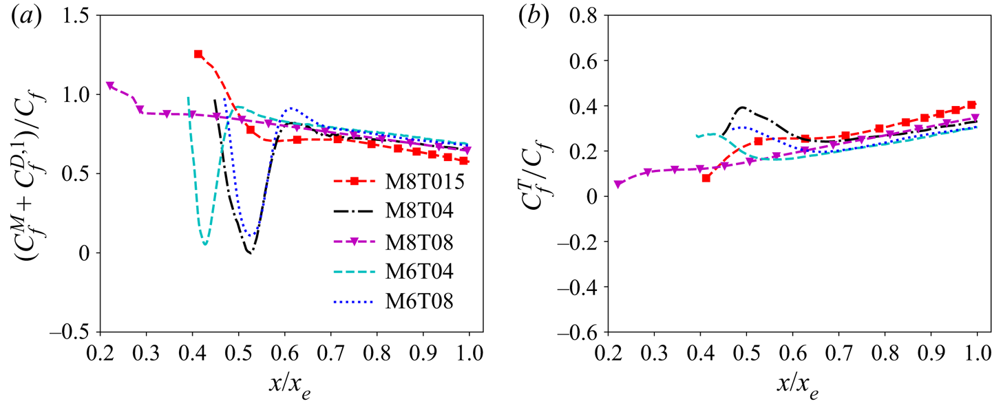
 $C_{f}$ in the hypersonic transitional and turbulent boundary layers are shown in figure 10. It is shown that the relative contributions of
 $C_{f}^{M}+C_{f}^{D,1}$ and
 $C_{f}^{T}$ to the skin-friction coefficient
 $C_{f}$ in M8T04 and M6T04 are similar to those in M8T08 and M6T08, respectively, in the fully developed region, indicating that the relative contributions of the mean convection and the Reynolds shear stress to the skin-friction coefficient have weak correlations with the wall temperature in hypersonic turbulent boundary layers, which is consistent with the observation in subsonic and supersonic turbulent boundary layers (Wenzel et al. Reference Wenzel, Gibis and Kloker2021a). This observation is satisfied in weakly cooled cases (including M6T04, M6T08, M8T04 and M8T08); however, the conclusion is not fully correct in the strongly cooled condition (i.e. M8T015) on account of the much stronger compressibility. In M8T015, the relative contribution of
 $C_{f}^{M}+C_{f}^{D,1}$ is smaller, whereas that of
 $C_{f}^{T}$ to the skin-friction coefficient
 $C_{f}$ is larger compared with those in M8T04 and M8T08, indicating that the strongly cooled wall condition can enhance the relative contribution of the Reynolds shear stress, and weaken the effect of the mean convection on the wall skin friction. It is noted that the relative contribution of each components essentially corresponds to a normalisation with the wall shear stress
 $\bar {\tau }_{w}$. Accordingly, it was concluded in Wenzel et al. (Reference Wenzel, Gibis and Kloker2021a) that due to the Morkovin's scaling, the relative contribution of
 $C_{f}^{T}$ is Mach-number invariant. However, as the Mach number increases and the wall temperature decreases, the compressibility effect is enhanced and the success of the Morkovin's scaling becomes increasingly weaker (Liang & Li Reference Liang and Li2013). Therefore, it is shown that the high-Mach-number condition and the extremely cooled wall temperature can enhance the effect of the Reynolds shear stress, and weaken the effect of the mean convection.
Streamwise evolutions of the relative contributions of (a)  $C_{f}^{M}+C_{f}^{D,1}$ and (b)
 $C_{f}^{T}$ to the skin-friction coefficient
 $C_{f}$ in the hypersonic transitional and turbulent boundary layers.

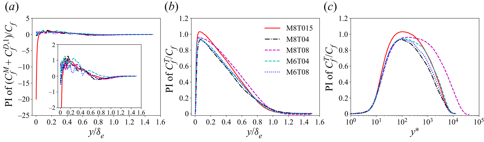
In order to investigate the wall-normal distributions of the integrands of the components in (3.3), the pre-multiplied integrands of the relative contributions of  $C_{f}^{M}+C_{f}^{D,1}$ and
 $C_{f}^{T}$ to the skin-friction coefficient
 $C_{f}$ in the hypersonic transitional and turbulent boundary layers at the streamwise position
 $x/x_{e}=0.95$ are shown in figure 11. Here
 $y^{*}$ is defined as
 $y^{*}=y/\delta ^{*}_{\nu }$, where
 $\delta ^{*}_{\nu }=\bar {\mu }/( \bar {\rho }u^{*} )$ represents the semi-local scaling and
 $u^{*}=\sqrt {\tau _{w}/\bar {\rho }}$. It is shown that the pre-multiplied integrands of
 $( C_{f}^{M}+C_{f}^{D,1} )/C_{f}$ of all five cases are positive in most regions across the boundary layer, resulting in the positive values of
 $( C_{f}^{M}+C_{f}^{D,1} )/C_{f}$. However, large negative values of the pre-multiplied integrand of
 $( C_{f}^{M}+C_{f}^{D,1} )/C_{f}$ appear in the near-wall region in M8T015, which lead to smaller values of
 $( C_{f}^{M}+C_{f}^{D,1} )/C_{f}$ in M8T015 compared with the other cases. Furthermore, the large negative values of the pre-multiplied integrand of
 $( C_{f}^{M}+C_{f}^{D,1} )/C_{f}$ near the wall are mainly contributed by the pre-multiplied integrand of
 $C_{f}^{M}/C_{f}$. Accordingly, the large wall-normal gradient of the mean streamwise velocity
 $\partial \tilde {u}/\partial y$ near the wall in the strongly cooled case gives rise to the smaller contribution of the mean convection to the wall skin friction.
Pre-multiplied integrands of the relative contributions of (a)  $C_{f}^{M}+C_{f}^{D,1}$ and (b)
 $C_{f}^{T}$ to the skin-friction coefficient
 $C_{f}$ in the hypersonic transitional and turbulent boundary layers at the streamwise position
 $x/x_{e}=0.95$. (c) Pre-multiplied integrands of the relative contributions of
 $C_{f}^{T}$ to the skin-friction coefficient
 $C_{f}$ in the semi-local scale. Here the abbreviation ‘PI’ represents the pre-multiplied integrand. It is noted that the pre-multiplied integrand of
 $( C_{f}^{M}+C_{f}^{D,1} )/C_{f}$ is defined as
 $-({2}/{\bar {\rho } _{\delta }\bar {u}_{\delta }^{2}C_{f}}) ( y_{b}-y ) (\bar {\rho }\tilde {v}({\partial \tilde {u}}/{\partial y})+\bar {\rho }\tilde {u}({\partial \tilde {u}}/{\partial x}))$, and the pre-multiplied integrand of
 $C_{f}^{T}/C_{f}$ is written as
 $-({2\bar {\rho }\widetilde {{u}''{v}''}}/{\bar {\rho } _{\delta }\bar {u}_{\delta }^{2}C_{f}})$.

Moreover, it is shown in figure 11(c) that the pre-multiplied integrands of  $C_{f}^{T}/C_{f}$ of all cases achieve their peak values in the buffer layer and are positive along wall-normal direction, leading to the positive values of
 $C_{f}^{T}/C_{f}$. The peak values of the pre-multiplied integrand of
 $C_{f}^{T}/C_{f}$ in M8T015 are larger than those in the other cases, which gives rise to larger values of
 $C_{f}^{T}/C_{f}$ in M8T015. This observation is mainly due to the reason that the strongly cooled wall temperature enhances the normalised Reynolds shear stress, and further increases the relative contribution of the Reynolds shear stress to the skin-friction coefficient.
5. Streamwise evolution of $C_{h}$

The streamwise evolutions of the heat-transfer coefficient  $C_{h}$ and its components in (3.4) in the hypersonic transitional and turbulent boundary layers are shown in figure 12. It is seen that the heat-transfer coefficient
 $C_{h}$ has the similar trend of the skin-friction coefficient
 $C_{f}$ along the streamwise direction, that is, it initially increases to the transition peak due to the bypass transition process, and then slightly decreases as the streamwise position
 $x/x_{e}$ increases. Similar to the behaviour of the skin-friction coefficient
 $C_{f}$, an overshoot also appears in the streamwise evolution of
 $C_{h}$, which was widely observed in previous investigations (Horvath et al. Reference Horvath, Berry and Hollis2002; Wadhams et al. Reference Wadhams, Mundy, Maclean and Holden2008; Franko et al. Reference Franko, Bhaskaran and Lele2011; Franko & Lele Reference Franko and Lele2013). It is also shown in figure 12(f) that the values of
 $C_{h}$ in the fully developed region increase significantly as the wall temperature decreases, implying that the cold wall temperature enhances the wall heat transfer.
Streamwise evolutions of the heat-transfer coefficient  $C_{h}$ and its components in (3.4) in the hypersonic transitional and turbulent boundary layers in (a) M8T015, (b) M8T04, (c) M8T08, (d) M6T04 and (e) M6T08. (f) Streamwise evolutions of the heat-transfer coefficient
 $C_{h}$ in five hypersonic transitional and turbulent boundary layers. The vertical dashed line represents the streamwise position of the transition peak.

The streamwise evolutions of the contributions of the heat-transfer coefficient  $C_{h}$ in (3.4) along the streamwise direction in hypersonic transitional and turbulent boundary layer are similar for different Mach numbers and wall temperatures. The vertical mean-convection term
 $C_{h}^{M}$ initially decreases at the incipient state of the bypass transition process, and then begins to increase at the centre of the bypass transition process. After the transition peak,
 $C_{h}^{M}$ increases to positive values and contributes positively to the heat-transfer coefficient
 $C_{h}$. The streamwise mean-convection term
 $C_{h}^{D,1}$ has the opposite trend along streamwise direction compared with
 $C_{h}^{M}$. It is shown that the terms
 $C_{h}^{M}$ and
 $C_{h}^{D,1}$ significantly contribute to the heat-transfer coefficient
 $C_{h}$, and represent the effect of the mean convection on the heat-transfer coefficient. The viscous-dissipation term
 $C_{h}^{V}$ increases due to the bypass transition process, and then slightly decreases after the transition peak. The magnitude of the turbulent-convection term
 $C_{h}^{T}$ slightly increases along the streamwise direction and gives the negative contribution to
 $C_{h}$, due to the reason that the Reynolds heat flux is enhanced along the streamwise direction. The pressure-dilatation term
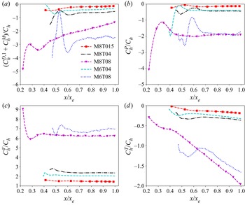
 $C_{h}^{P}$ has large negative values in the transitional and fully developed regions. The spatial-development term
 $C_{h}^{D,2}$ only has small values in the bypass transition process, and becomes almost zero after the transition peak, implying that the streamwise gradient of the fluctuating streamwise velocity-temperature correlation only has a limited contribution to the heat-transfer coefficient in the transition process. Other terms in (3.4) are nearly zero in the transitional and turbulent boundary layers.
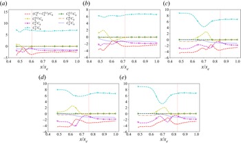
The streamwise evolutions of the relative contributions of the components in (3.4) to the heat-transfer coefficient  $C_{h}$ in the hypersonic transitional and turbulent boundary layers are shown in figure 13. It is seen that the viscous-dissipation term
 $C_{h}^{V}$ gives the dominant positive contribution, which is consistent with the observation in supersonic turbulent channel flows by Zhang & Xia (Reference Zhang and Xia2020), whereas the terms
 $C_{h}^{M}+C_{h}^{D,1}$,
 $C_{h}^{P}$ and
 $C_{h}^{T}$ give the negative contributions to the heat-transfer coefficient
 $C_{h}$ along the transitional and turbulent boundary layers. The spatial-development term
 $C_{h}^{D,2}$ contributes positively at the onset of the bypass transition process, and then switches to negative at the centre of the transition process. After the transition peak, the flow evolves to the fully developed state, and the streamwise gradient of the fluctuating streamwise velocity-temperature correlation (i.e.
 $C_{h}^{D,2}$) decreases to almost zero.
Streamwise evolutions of the relative contributions of the components in (3.4) to the heat-transfer coefficient  $C_{h}$ in the hypersonic transitional and turbulent boundary layers in (a) M8T015, (b) M8T04, (c) M8T08, (d) M6T04 and (e) M6T08. The vertical dashed line represents the streamwise position of the transition peak.

Similar to the skin-friction coefficient  $C_{f}$, a hint for the underlying mechanism of the overshoot phenomenon of the heat-transfer coefficient can be given based on the integral analysis as follows. It is seen that at the transition peak, the effect of viscous dissipation gives the main positive contribution and strengthens the overshoot, whereas the effects of the pressure dilatation, mean convection and the Reynolds heat flux contribute negatively to the heat-transfer coefficient
 $C_{h}$ and weaken the overshoot. This observation is not consistent with the previous reason of the overshoot of
 $C_{h}$ in Franko & Lele (Reference Franko and Lele2013). Franko & Lele (Reference Franko and Lele2013) showed that the transport of thermal energy and the Reynolds heat flux lead to an increase in wall heat transfer and correspond to the overshoot, which is opposite to the above observation that the Reynolds heat flux weakens the overshoot phenomenon. Here, it is shown that the overshoot phenomenon of the heat-transfer coefficient
 $C_{h}$ is mainly caused by the viscous-dissipation effect. Its underlying mechanism can be explained as follows. The large-amplitude fluctuations of the instability waves significantly change the mean velocity profiles, and the strong mean velocity gradient leads to strong viscous dissipation, which further results in the overshoot of
 $C_{h}$.
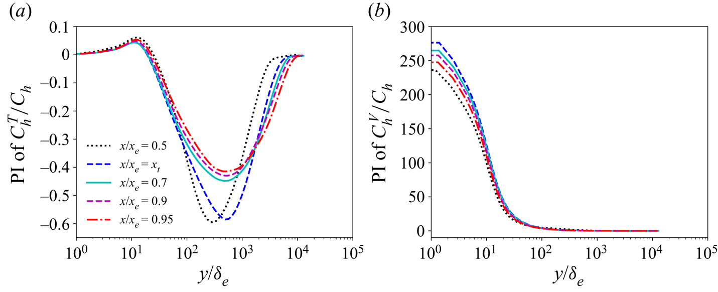
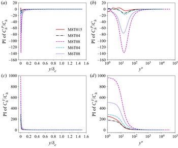
The pre-multiplied integrands of the relative contributions of  $C_{h}^{T}$ to the heat-transfer coefficient
 $C_{h}$ at different streamwise positions in M8T015 are shown in figure 14(a). Similar to the behaviours of the pre-multiplied integrand of the relative contribution of
 $C_{f}^{T}$ (i.e. the opposition of the normalised Reynolds shear stress), the peak values of the pre-multiplied integrand of the relative contribution of
 $C_{h}^{T}$ (i.e. the normalised Reynolds heat flux) are much larger in the transition region than those in the fully developed region, which is consistent with the fact observed in Franko & Lele (Reference Franko and Lele2013) that a peak value of the normalised Reynolds heat flux exists at the transition peak. These statistical observations are coincident with the instantaneous field of
 ${T}''$ shown in figure 6. It can be seen in figure 6 that the structures of
 ${T}''$ are much thicker in the transition region than those in the fully developed region, and the magnitudes of the fluctuation
 ${T}''$ are much larger in the transition region than those in the fully developed region, resulting in the much larger peak values of the normalised Reynolds heat flux in the transition region. Nevertheless, the areas under the curves of the pre-multiplied integrand of the relative contribution of
 $C_{h}^{T}$ in the transition region are much smaller than those in the fully developed region, indicating the smaller contribution of
 $C_{h}^{T}$ to
 $C_{h}$ at the transition peak than that in the fully developed region. Moreover, the values of the pre-multiplied integrand of the relative contribution of
 $C_{h}^{T}$ are negative in most region across the boundary layer, which gives rise to the negative contribution of
 $C_{h}^{T}$ to
 $C_{h}$. Accordingly, the peak values of the normalised Reynolds heat flux are not the main reason of the overshoot of
 $C_{h}$ as Franko & Lele (Reference Franko and Lele2013) stated.
Pre-multiplied integrands of the relative contributions of (a)  $C_{h}^{T}$, (b)
 $C_{h}^{V}$ to the heat-transfer coefficient
 $C_{h}$ at different streamwise positions in M8T015. Here the abbreviation ‘PI’ represents the pre-multiplied integrand. The pre-multiplied integrand of
 $C_{h}^{T}/C_{h}$ is written as
 $-({C_{v}\bar {\rho }\widetilde {{T}''{v}''}}/{ ( \bar {\rho } _{\delta }\bar {u}_{\delta }C_{p} ( T_{r}-T_{w} ) )C_{h}})$; the pre-multiplied integrand of
 $C_{h}^{V}/C_{h}$ is defined as
 $({C_{v}}/{ ( \bar {\rho } _{\delta }\bar {u}_{\delta }C_{p} ( T_{r}-T_{w} ) )C_{h}}) ( y_{b}-y )\overline {({\sigma _{ij}}/{C_{v}Re})({\partial u_{i}}/{\partial x_{j}})}$. It is noted that the behaviours of the above quantities in other four cases are similar to those in M8T015, and are omitted here for brevity.

The pre-multiplied integrand of the relative contribution of  $C_{h}^{V}$ to the heat-transfer coefficient
 $C_{h}$ at different streamwise positions in M8T015 are shown in figure 14(b). It is shown that the values of the pre-multiplied integrand of the relative contribution of
 $C_{h}^{V}$ at the transition peak are much larger than those at other streamwise positions, which suggests that the strong viscous dissipation near the wall is the appropriate major reason of the overshoot of
 $C_{h}$. Further investigation shows that the large values of the pre-multiplied integrand of the relative contribution of
 $C_{h}^{V}$ are mainly due to the strong positive wall-normal gradient of the streamwise velocity
 $\partial \tilde {u}/\partial y$ near the wall.
The streamwise evolutions of the relative contributions of  $C_{h}^{D,1}+C_{h}^{M}$,
 $C_{h}^{P}$,
 $C_{h}^{V}$ and
 $C_{h}^{T}$ to the heat-transfer coefficient
 $C_{h}$ in the hypersonic transitional and turbulent boundary layers with different Mach numbers and wall temperatures are shown in figure 15. In contrast to the relatively weak correlation between the relative contributions to the skin-friction coefficient
 $C_{f}$ and the wall temperature, the relative contributions to the heat-transfer coefficient
 $C_{h}$ is strongly influenced by the wall temperature. It is shown that after the transition peak, the magnitudes of the relative contributions of
 $C_{h}^{P}$ and
 $C_{h}^{V}$ are almost constant, whereas that of
 $(C_{h}^{D,1}+C_{h}^{M} )/C_{h}$ decreases slightly, and that of
 $C_{h}^{T}/C_{h}$ increases mildly along the streamwise direction. Moreover, the magnitudes of
 $(C_{h}^{D,1}+C_{h}^{M} )/C_{h}$,
 $C_{h}^{P}/C_{h}$,
 $C_{h}^{V}/C_{h}$ and
 $C_{h}^{T}/C_{h}$ decrease significantly as the wall temperature decreases in the fully developed state of the hypersonic boundary layers. However, the larger magnitudes of these components cancel each other out and, finally, result in the smaller values of the heat-transfer coefficient
 $C_{h}$ in weakly cooled cases.
Streamwise evolutions of the relative contributions of (a)  $C_{h}^{D,1}+C_{h}^{M}$, (b)
 $C_{h}^{P}$, (c)
 $C_{h}^{V}$ and (d)
 $C_{h}^{T}$ to the heat-transfer coefficient
 $C_{h}$ in the hypersonic transitional and turbulent boundary layers.

The pre-multiplied integrands of the relative contributions of  $C_{h}^{P}$ and
 $C_{h}^{V}$ to the heat-transfer coefficient
 $C_{h}$ in the hypersonic transitional and turbulent boundary layers at the streamwise position
 $x/x_{e}=0.95$ are shown in figure 16. It is observed that the magnitudes of the pre-multiplied integrand of
 $C_{h}^{P}/C_{h}$ achieve their peak values in the buffer layer, indicating that the pressure-dilatation effect is dominant in the buffer layer. Furthermore, the peak values of the magnitudes of the pre-multiplied integrand of
 $C_{h}^{P}/C_{h}$ increase as the wall temperature increases, and the small positive peak values appear in the near-wall region only in the strongly cooled case (i.e. M8T015). These observations can be explained as follows. According to the definition of the pressure-dilatation term in (3.17), if the mean pressure dilatation
 $\overline {\rho ( \gamma -1 )T({\partial u_{j}}/{\partial x_{j}})}$ is positive, the pre-multiplied integrand of
 $C_{h}^{P}/C_{h}$ is negative, and vice versa. It is noted that the mean pressure dilatation is highly related to the velocity divergence. It was known that the mean flow in compressible turbulent boundary layers tends to be expansive as pointed out in Wang & Lu (Reference Wang and Lu2012); accordingly, the mean velocity divergence should be positive and the pre-multiplied integrand of
 $C_{h}^{P}/C_{h}$ should be negative across the turbulent boundary layer, as shown in figure 16(a). Furthermore, it was shown that the cold wall temperature can enhance the compression motions in the near-wall region in previous investigations (Xu et al. Reference Xu, Wang, Wan, Yu, Li and Chen2021a,Reference Xu, Wang, Wan, Yu, Li and Chenb), thus the positive values of the mean velocity divergence should decrease as the wall temperature decreases across the turbulent boundary layer, and the mean velocity divergence can be negative near the wall due to strong cooling of the wall (i.e. M8T015) (Xu et al. Reference Xu, Wang, Wan, Yu, Li and Chen2021a). This further leads to the negative values of the pre-multiplied integrand of
 $C_{h}^{P}/C_{h}$ across the turbulent boundary layer, and the decrease of the negative values of the pre-multiplied integrand of
 $C_{h}^{P}/C_{h}$ as the wall temperature decreases. Therefore, the area under the curve of the pre-multiplied integrand of the relative contributions of
 $C_{h}^{P}$ in the linear-scaling
 $x$-axis is negative and decreases as the wall temperature decreases, resulting in the observation in figure 15 that the magnitude of the negative contribution of
 $C_{h}^{P}/C_{h}$ decreases as the wall temperature decreases.
Pre-multiplied integrands of the relative contributions of (a),(b)  $C_{h}^{P}$ and (c),(d)
 $C_{h}^{V}$ to the heat-transfer coefficient
 $C_{h}$ in the hypersonic transitional and turbulent boundary layers at the streamwise position
 $x/x_{e}=0.95$. Here the abbreviation ‘PI’ represents the pre-multiplied integrand. The pre-multiplied integrand of
 $C_{h}^{P}/C_{h}$ is expressed as
 $-({C_{v}}/{ ( \bar {\rho } _{\delta }\bar {u}_{\delta }C_{p} ( T_{r}-T_{w} ) )C_{h}}) ( y_{b}-y )\overline {\rho ( \gamma -1 )T({\partial u_{j}}/{\partial x_{j}})}$, and the pre-multiplied integrand of
 $C_{h}^{V}/C_{h}$ is defined as
 $({C_{v}}/{ ( \bar {\rho } _{\delta }\bar {u}_{\delta }C_{p} ( T_{r}-T_{w} ) )C_{h}}) (y_{b}-y )\overline {({\sigma _{ij}}/{C_{v}Re})({\partial u_{i}}/{\partial x_{j}})}$.

It is shown in figures 16(c) and 16(d) that the pre-multiplied integrand of  $C_{h}^{V}/C_{h}$ is dominant in the near-wall region, and sharply decreases away from the wall, which indicates that the effect of the viscous dissipation is dominant near the wall, and is consistent with the previous observations (Duan et al. Reference Duan, Beekman and Martin2010; Xu et al. Reference Xu, Wang, Wan, Yu, Li and Chen2021b). Moreover, the area under the curve of the pre-multiplied integrand of
 $C_{h}^{V}/C_{h}$ in the linear-scaling
 $x$-axis decreases as the wall temperature decreases, which further leads to the decrease of the
 $C_{h}^{V}/C_{h}$ with more cooled wall shown in figure 15.
The pre-multiplied integrand of the relative contribution of  $C_{h}^{T}$ to the heat-transfer coefficient
 $C_{h}$ and the normalised Reynolds heat flux
 $C_{v}\bar {\rho }\widetilde {{T}^{\prime \prime }{v}^{\prime \prime }}/ (\bar {\rho } _{\delta }\bar {u}_{\delta }C_{p}C_{h} ( T_{r}-T_{w} ) )$ along wall-normal direction at the streamwise position
 $x/x_{e}=0.95$ are shown in figures 17(a) and 17(b). It is shown that the normalised Reynolds heat flux is slightly negative in strongly cooled cases (including M8T015, M8T04 and M6T04) near the wall, and then switches to positive as the wall-normal distance increases; whereas for the weakly cooled cases (including M8T08 and M6T08), the normalised Reynolds heat flux is positive along the wall-normal direction. This can be explained as follows. According to the idea in Prandtl's mixing-length theory, the Reynolds heat flux
 $\bar {\rho }\widetilde {{T}^{\prime \prime }{v}^{\prime \prime }}$ is negatively correlated with the mean temperature gradient
 $\partial \tilde {T}/\partial y$. The negative values of the Reynolds heat flux are correlated with the positive mean temperature wall-normal gradient near the wall in M8T015, M8T04 and M6T04, as shown in figures 17(c) and 17(d). As the wall-normal distance increases, the mean temperature wall-normal gradient becomes negative, and results in the positive Reynolds heat flux. The location of the peak values of the Reynolds heat flux is consistent with the location where the mean temperature wall-normal gradient is largest. Furthermore, the Reynolds heat flux decreases as the wall temperature decreases, which is mainly due to the reason that the mean temperature wall-normal gradient is smaller with colder wall temperature. It is noted that the pre-multiplied integrand of the relative contribution of
 $C_{h}^{T}$ to the heat-transfer coefficient
 $C_{h}$ is opposite to the normalised Reynolds heat flux
 $C_{v}\bar {\rho }\widetilde {{T}^{\prime \prime }{v}^{\prime \prime }}/ (\bar {\rho } _{\delta }\bar {u}_{\delta }C_{p}C_{h} ( T_{r}-T_{w} ) )$. Thus, in contrast to the normalised Reynolds heat flux, the pre-multiplied integrand of the relative contribution of
 $C_{h}^{T}$ to the heat-transfer coefficient
 $C_{h}$ is negative in most regions along the wall-normal direction, which further results in the negative contribution to the heat-transfer coefficient
 $C_{h}$. As the wall temperature decreases, the decrease of the Reynolds heat flux gives rise to the decrease of the relative contribution
 $C_{h}^{T}/C_{h}$.
(a) Pre-multiplied integrand of the relative contribution of  $C_{h}^{T}$ to the heat-transfer coefficient
 $C_{h}$ in the hypersonic transitional and turbulent boundary layers at the streamwise position
 $x/x_{e}=0.95$. Here the abbreviation ‘PI’ represents the pre-multiplied integrand. (b) Normalised Reynolds heat flux
 $C_{v}\bar {\rho }\widetilde {{T}^{\prime \prime }{v}^{\prime \prime }}/ (\bar {\rho } _{\delta }\bar {u}_{\delta }C_{p}C_{h} ( T_{r}-T_{w} ) )$ along wall-normal direction at
 $x/x_{e}=0.95$. (c),(d) Normalised mean temperature profiles
 $\tilde {T}/T_{\infty }$ along wall-normal direction at
 $x/x_{e}=0.95$ with (c) linear-scaling
 $x$-axis and (d) log-scaling
 $x$-axis. The pre-multiplied integrand of
 $C_{h}^{T}/C_{h}$ is written as
 $-({C_{v}\bar {\rho }\widetilde {{T}''{v}''}}/ { ( \bar {\rho } _{\delta }\bar {u}_{\delta }C_{p} ( T_{r}-T_{w} ) )C_{h}})$.

6. Remarks on the conclusions
6.1. Influence of the wall blowing and suction disturbance parameters $A$ and $\beta$ on the skin-friction and heat-transfer coefficients


The streamwise evolutions of the relative contributions of the components in (3.3) to the skin-friction coefficient  $C_{f}$ and that of the components in (3.4) to the heat-transfer coefficient
 $C_{h}$ in M6T08 with different values of the wall blowing and suction disturbance parameters
 $A$ and
 $\beta$ are shown in figures 18 and 19, respectively. It is shown in figure 18 that the value of
 $C_{f}^{T}/C_{f}$ at the transition peak is smaller than that in the fully developed state, whereas that of
 $(C_{f}^{M}+C_{f}^{D,1} )/C_{f}$ at the transition peak is larger than that in the fully developed state, which are consistent with the facts observed in compressible boundary layers at Mach numbers 6 and 8 with different wall temperatures shown in figure 8. Accordingly, the overshoot of the skin-friction coefficient
 $C_{f}$ in M6T08 with different values of
 $A$ and
 $\beta$ is also mainly caused by the drastic change of the mean velocity profiles, especially the strong negative
 $\partial \tilde {u}/\partial x$ in the far-wall region. Moreover, it is shown in figure 19 that the viscous-dissipation term
 $C_{h}^{V}$ gives the dominant positive contribution to the heat-transfer coefficient
 $C_{h}$, whereas the Reynolds heat flux term
 $C_{h}^{T}$ contributes negatively to
 $C_{h}$, which are coincident with the observations shown in figure 13. Thus, the overshoot of the heat-transfer coefficient
 $C_{h}$ in M6T08 with different values of
 $A$ and
 $\beta$ is also mainly due to the strong viscous dissipation near the wall, especially the strong positive
 $\partial \tilde {u}/\partial y$ in the near-wall region. To sum up, in our numerical simulations, the values of the wall blowing and suction disturbance parameters
 $A$ and
 $\beta$ do not affect the main reasons of the overshoot of the skin-friction and heat-transfer coefficients at the transition peak.
Streamwise evolutions of the relative contributions of the components in (3.3) to the skin-friction coefficient  $C_{f}$ in (a) M6T08-A, (b) M6T08-B, (c) M6T08-C, (d) M6T08-D and (e) M6T08-E. The vertical dashed line represents the streamwise position of the transition peak.

Streamwise evolutions of the relative contributions of the components in (3.4) to the heat-transfer coefficient  $C_{h}$ in (a) M6T08-A, (b) M6T08-B, (c) M6T08-C, (d) M6T08-D and (e) M6T08-E. The vertical dashed line represents the streamwise position of the transition peak.

6.2. Additional remarks on the major reasons for the overshoot phenomena
It is noted that the dominant term in the FIK-like decomposition may change due to the different value of the number of integration. Therefore, the influence of the number of integration on the major reasons of the overshoot phenomena should be clarified.
It is noted that with the arbitrary value of the number of integration, the term associated with the Reynolds heat flux (i.e.  $C_{h}^{T}$) is always negative and contributes negatively to the wall heat-transfer coefficient. The only positive term among the decomposition terms is the term associated with the viscous dissipation (i.e.
 $C_{h}^{V}$). Therefore, the major reason for the overshoot of the heat-transfer coefficient is the viscous dissipation. Then, the only debate is the major reason of the overshoot of the skin-friction coefficient. We have checked that at the transition peak, the relative contribution of the mean-convection term (i.e.
 $C_{f}^{M}+C_{f}^{D,1}$) is larger than that of the Reynolds shear stress term (i.e.
 $C_{f}^{T}$) based on the threefold FIK decomposition, which is qualitatively similar to the situation of the twofold FIK decomposition. To sum up, the qualitative conclusions of the major reasons of the overshoot phenomena are the same in the twofold and threefold FIK decomposition.
7. Summary and conclusions
In this paper, the decompositions of the skin-friction and heat-transfer coefficients based on the twofold repeated integration in hypersonic transitional and turbulent boundary layers with different Mach numbers and wall temperatures are analysed to reveal the underlying mechanisms of the generations of the wall skin friction and heat transfer. The possible reasons of the overshoot of wall skin friction and heat transfer based on the integral analysis are observed. It is shown that the Reynolds analogy factor is small in the laminar state, and then increases due to the bypass transition process. An overshoot is also observed at the transition peak, which is similar to the behaviours of the skin-friction and heat-transfer coefficients. It is also shown that the Reynolds analogy factor slightly increases as the wall temperature decreases, especially for the extremely cooled wall.
The values of the skin-friction coefficient in the hypersonic turbulent boundary layers increase as the wall temperature decreases. It is shown that the mean convection, the Reynolds shear stress, the streamwise pressure gradient and the streamwise normal Reynolds stress gradient are important mechanisms during the bypass transition process in the integral sense. The overshoot of the skin-friction coefficient is mainly caused by the rapid change of the mean velocity profiles, especially the strong negative  $\partial \tilde {u}/\partial x$ in the far-wall region, rather than the Reynolds shear stress inferred by Franko & Lele (Reference Franko and Lele2013) in the integral sense. In the hypersonic turbulent boundary layers, only the effects of the mean convection and the Reynolds shear stress contribute positively to the skin-friction coefficient, where the effect of the mean convection has the dominant contribution to
 $C_{f}$. Furthermore, the relative contributions of the mean convection and the Reynolds shear stress to the skin-friction coefficient have weak correlations with the wall temperature in hypersonic turbulent boundary layers, except for the strongly cooled wall condition. It is shown that the strongly cooled wall condition and high Mach number can enhance the effect of the Reynolds shear stress, and weaken the effect of the mean convection. Further investigation indicates that the smaller relative contribution of the mean convection in the strongly cooled case is mainly due to the large wall-normal gradient of the mean streamwise velocity
 $\partial \tilde {u}/\partial y$ near the wall, whereas the larger relative contribution of the Reynolds shear stress is primarily caused by the enhancement of the normalised Reynolds shear stress by the strongly cooled wall.
Moreover, the heat-transfer coefficient in the hypersonic turbulent boundary layers increases as the wall temperature decreases. It is noted that the positive contribution to the wall heat flux means that the component enhances the heat-transfer coefficient, and contributes the internal energy from the whole boundary layer to the wall heat flux in the integral sense. In contrast, the negative contribution means that the component reduces the heat-transfer coefficient, and carries the extra internal energy from the wall heat flux to the boundary layer in the integral sense (Sun et al. Reference Sun, Guo, Yuan, Zhang, Li and Liu2021). The effect of the viscous dissipation gives the dominant positive contribution, whereas the mean convection, pressure dilatation and the Reynolds heat flux give the negative contributions to the heat-transfer coefficient along the transitional and turbulent boundary layers. The overshoot of the heat-transfer coefficient is primarily caused by the viscous dissipation, especially the strong positive  $\partial \tilde {u}/\partial y$ in the near-wall region, rather than the Reynolds heat flux inferred by Franko & Lele (Reference Franko and Lele2013) in the integral sense. It is shown that the magnitudes of the relative contributions of the mean convection, pressure dilatation, viscous dissipation and the Reynolds heat flux increase as the wall temperature increases in the hypersonic turbulent boundary layers. It was shown that the cold wall temperature can enhance the compression motions in the near-wall region in previous investigations (Xu et al. Reference Xu, Wang, Wan, Yu, Li and Chen2021a,Reference Xu, Wang, Wan, Yu, Li and Chenb), which further leads to the decrease of the magnitude of the relative contribution of the pressure dilatation with colder wall temperature. It is also seen that the effect of the viscous dissipation is dominant near the wall, and sharply decreases away from the wall. Furthermore, the decrease of the relative contribution of the Reynolds heat flux is mainly due to the smaller mean temperature wall-normal gradient with colder wall temperature.
The influence of the wall blowing and suction disturbance parameters  $A$ and
 $\beta$ on the skin-friction and heat-transfer coefficients is also observed. It is shown that the values of
 $A$ and
 $\beta$ do not affect the major reasons of the overshoot of the skin-friction and heat-transfer coefficients at the transition peak.
In conclusion, the underlying mechanisms of the generations of the wall skin friction and heat transfer are revealed in the hypersonic transitional and turbulent boundary layers. The reasons for the overshoot of the skin-friction and heat-transfer coefficients are studied based on the integral analysis, which could be helpful for the skin friction reduction and thermal protection in hypersonic aircrafts.
Funding
This work was supported by the NSFC Basic Science Center Program (grant no. 11988102), by National Natural Science Foundation of China (NSFC grant nos 91952104, 92052301, 12172161 and 91752201), by the Technology and Innovation Commission of Shenzhen Municipality (grant nos KQTD20180411143441009 and JCYJ20170412151759222), and by Department of Science and Technology of Guangdong Province (grant no. 2019B21203001). This work was also supported by Center for Computational Science and Engineering of Southern University of Science and Technology.
Declaration of interests
The authors report no conflict of interest.
Appendix A. Governing equations of the compressible Navier–Stokes equations
The compressible Navier–Stokes equations are non-dimensionalised by the following set of reference scales, including the reference length  $L_{\infty }$, free-stream density
 $\rho _{\infty }$, velocity
 $U_{\infty }$, temperature
 $T_{\infty }$, pressure
 $p_{\infty }= \rho _{\infty }U_{\infty }^{2}$, energy per unit volume
 $\rho _{\infty }U_{\infty }^{2}$, viscosity
 $\mu _{\infty }$ and thermal conductivity
 $\kappa _{\infty }$. Three non-dimensional governing parameters are introduced, namely the Reynolds number
 $Re= \rho _{\infty }U_{\infty }L_{\infty }/\mu _{\infty }$, the Mach number
 $M= U_{\infty }/c_{\infty }$ and Prandtl number
 $Pr= \mu _{\infty } C_{p}/\kappa _{\infty }$. The ratio of specific heat at constant pressure
 $C_{p}$ to that at constant volume
 $C_{v}$ is defined as
 $\gamma = C_{p}/C_{v}$ and assumed to be equal to 1.4. The parameter
 $\alpha$ is given by
 $\alpha = Pr\,Re ( \gamma -1 )M^{2}$, where
 $Pr=0.7$.
The following compressible dimensionless Navier–Stokes equations in the conservative form are solved numerically (Liang & Li Reference Liang and Li2015; Xu et al. Reference Xu, Wang, Wan, Yu, Li and Chen2021a)
 \begin{gather} \frac{\partial \rho }{\partial t}+\frac{\partial (\rho u_{j})}{\partial x_{j}}=0, \end{gather}
 \begin{gather} \frac{\partial \left ( \rho u_{i} \right )}{\partial t}+\frac{\partial [\rho u_{i}u_{j}+p\delta _{ij}]}{\partial x_{j}}=\frac{1}{Re}\frac{\partial \sigma _{ij}}{\partial x_{j}}, \end{gather}
 \begin{gather} \frac{\partial E}{\partial t}+\frac{\partial [ \left ( E+p \right )u_{j}]}{\partial x_{j}}=\frac{1}{\alpha }\frac{\partial }{\partial x_{j}}\left ( \kappa \frac{\partial T}{\partial x_{j}} \right )+\frac{1}{Re}\frac{\partial (\sigma _{ij}u_{i})}{\partial x_{j}}, \end{gather}
 \begin{gather} p=\rho T/(\gamma M^{2}), \end{gather}
where  $\rho$,
 $u_{i}$,
 $T$ and
 $p$ are the density, velocity component, temperature and pressure, respectively. The viscous stress
 $\sigma _{ij}$ is defined as
 \begin{equation} \sigma _{ij}=\mu \left ( \frac{\partial u_{i}}{\partial x_{j}}+\frac{\partial u_{j}}{\partial x_{i}} \right )-\frac{2}{3}\mu \theta \delta _{ij}, \end{equation}
where  $\theta = \partial u_{k}/\partial x_{k}$ is the velocity divergence. The total energy per unit volume
 $E$ is
 \begin{equation} E=\frac{p}{\gamma -1}+\frac{1}{2}\rho (u_{j}u_{j}). \end{equation}
The convection terms of the compressible governing equations are approximated by a seventh-order weighted essentially non-oscillatory scheme (Balsara & Shu Reference Balsara and Shu2000), and the viscous terms are discretised by an eighth-order central difference scheme. A third-order total variation diminishing type of Runge–Kutta method is applied for time advancing (Shu & Osher Reference Shu and Osher1988; Liang & Li Reference Liang and Li2013).
Furthermore, the governing equation of the internal energy can be expressed as
 \begin{equation} \frac{\partial (\rho C_{v}T)}{\partial t}+\frac{\partial (\rho C_{v}Tu_{j})}{\partial x_{j}}={-}\rho \left( \gamma-1 \right)C_{v}T\frac{\partial u_{j}}{\partial x_{j}}+\frac{\sigma_{ij}}{Re}\frac{\partial u_{i}}{\partial x_{j}}+\frac{1}{\alpha}\frac{\partial }{\partial x_{j}}\left( \kappa\frac{\partial T}{\partial x_{j}} \right). \end{equation}
Therefore, the stationary Reynolds averages of density, momentum and internal energy equations are defined as
 \begin{gather} \frac{\partial (\bar{\rho }\tilde{u}_{j})}{\partial x_{j}}=0, \end{gather}
 \begin{gather} \frac{\partial (\bar{\rho }\tilde{u}_{i}\tilde{u}_{j})}{\partial x_{j}}+\frac{\partial \left ( \overline{\rho {u}''_{i}{u}''_{j}} \right )}{\partial x_{j}}={-}\frac{\partial \bar{p}\delta _{ij}}{\partial x_{j}}+\frac{\partial \overline{\sigma }_{ij}}{\partial x_{j}}, \end{gather}
 \begin{gather} \frac{\partial (\bar{\rho} \tilde{T}\tilde{u}_{j})}{\partial x_{j}}+\frac{\partial \left ( \overline{\rho {T}''{u}''_{j}} \right )}{\partial x_{j}}={-}\overline{\rho \left ( \gamma -1 \right )T\frac{\partial u_{j}}{\partial x_{j}}}+\overline{\frac{\sigma _{ij}}{C_{v}Re}\frac{\partial u_{i}}{\partial x_{j}}}+\overline{\frac{1}{C_{v}\alpha }\frac{\partial }{\partial x_{j}}\left ( \kappa \frac{\partial T}{\partial x_{j}} \right )}. \end{gather}
Appendix B. Derivations of the $n$ repeated integration of the skin-friction and heat-transfer coefficients

Cauchy's formula indicates that  $n$ repeated integrations of a continuous function can be expressed as a single integral (Wenzel et al. Reference Wenzel, Gibis and Kloker2021a)
 \begin{equation} \int_{y_{l}}^{y_{b}}\int_{y_{l}}^{y_{2}}\cdots \int_{y_{l}}^{y_{n-1}}f\left (y_{n} \right )\,{\rm d}y_{n}\cdots {\rm d}y_{2}\,{{\rm d} y}=\frac{1}{\left ( n-1 \right )!}\int_{y_{l}}^{y_{b}}\left ( y_{b}-y \right )^{n-1}f\left ( y \right )\,{{\rm d} y}. \end{equation}
If  $n$ repeated integrations are applied on (3.1) and (3.2), according to Cauchy's formula equation (B 1), the skin-friction coefficient
 $C_{f}$ and heat-transfer coefficient
 $C_{h}$ can be expressed as
 \begin{align} C_{f}&=\frac{2\left ( n-1 \right )}{\bar{\rho} _{\delta }\bar{u}_{\delta }^{2}y_{b}^{n-1}}\int_{0}^{y_{b}}\left ( y_{b}-y \right )^{n-2}\left [ \frac{1}{Re}\left ( \bar{\mu }\frac{\partial \bar{u}}{\partial y}+\bar{\mu }\frac{\partial \bar{v}}{\partial x}+ \overline{{\mu }'\left ( \frac{\partial {u}'}{\partial y}+\frac{\partial {v}'}{\partial x} \right )}\right )-\bar{\rho }\widetilde{{u}''{v}''} \right ]\,{{\rm d} y}\nonumber\\ &\quad+\frac{2}{\bar{\rho} _{\delta }\bar{u}_{\delta }^{2}y_{b}^{n-1}}\int_{0}^{y_{b}}\left ( y_{b}-y \right )^{n-1}\left [ -\bar{\rho }\tilde{u}\frac{\partial \tilde{u}}{\partial x}-\bar{\rho }\tilde{v}\frac{\partial \tilde{u}}{\partial y}-\frac{\partial \bar{p}}{\partial x} +\!\frac{1}{Re}\frac{\partial \bar{\sigma}_{xx} }{\partial x}\!-\frac{\partial (\bar{\rho }\widetilde{{u}''{u}''})}{\partial x}\right ]\,{{\rm d} y},\end{align}
 \begin{align} C_{h}&=\frac{C_{v}\left
(n-1 \right )}{(\bar{\rho} _{\delta }\bar{u}_{\delta
}C_{p}(T_{r}-T_{w} ))y_{b}^{n-1}}\int_{0}^{y_{b}}\left (
y_{b}-y \right )^{n-2}\left [\overline{\frac{1}{C_{v}\alpha
}\left ( \kappa \frac{\partial T}{\partial y} \right
)}-\bar{\rho }\widetilde{{T}''{v}''} \right ]\,{{\rm d}
y}\nonumber\\ &\quad +\frac{C_{v}}{(\bar{\rho} _{\delta
}\bar{u}_{\delta }C_{p}(T_{r}-T_{w}
))y_{b}^{n-1}}\int_{0}^{y_{b}}\left ( y_{b}-y \right
)^{n-1}\left [-\bar{\rho }\tilde{u}\frac{\partial
\tilde{T}}{\partial x}-\bar{\rho }\tilde{v}\frac{\partial
\tilde{T}}{\partial y} \right ]\,{{\rm d}y}\nonumber\\
&\quad+\frac{C_{v}}{(\bar{\rho} _{\delta }\bar{u}_{\delta
}C_{p}(T_{r}\!-\!T_{w}))y_{b}^{n-1}}\int_{0}^{y_{b}}\left (
y_{b}-y \right )^{n-1}\left [-\frac{\partial \left
(\bar{\rho }\widetilde{{T}''{u}''} \right )}{\partial
x}-\overline{\rho \left ( \gamma -1 \right )T\frac{\partial
u_{j}}{\partial x_{j}}} \right ]\,{{\rm d} y}\nonumber\\
&\quad +\frac{C_{v}}{(\bar{\rho} _{\delta }\bar{u}_{\delta
}C_{p}(
T_{r}-T_{w}))y_{b}^{n-1}}\int_{0}^{y_{b}}\left ( y_{b}-y
\right )^{n-1}\left [\overline{\frac{\sigma
_{ij}}{C_{v}Re}\frac{\partial u_{i}}{\partial
x_{j}}}+\overline{\frac{1}{C_{v}\alpha }\frac{\partial
}{\partial x}\left ( \kappa \frac{\partial T}{\partial x}
\right )} \right ]\,{{\rm d} y},
\end{align}
where  $y_{b}$ is the upper integration limit.